Transformer Based 15 Level MLI for PVCELL Applications
S. Suri Babu & S.Rajsekhar
P.G Scholar, Department of EEE, ASR College of Engineering &Technology, JNTUK, A.P
Assistant Professor, Department of EEE, ASR College of Engineering &Technology, JNTUK, A.P
Abstract:
This study presents a novel topology for multilevel inverters so called cascaded transformer inverter (CTRSI). This topology consists of one DC source and several phase transformers. Each single-phase transformers generates three levels with four semiconductor switches and only two switches for all transformers alter the direction of single DC source.Whereas each single-phase transformers in conventional cascaded transformer multilevel inverter includes more switches. Hence, CTRSI has the advantage of a reduced number of components compared with conventional cascaded transformer multilevel inverter. Simulation results carried out by MATLAB/SIMULINK.The results show that the proposed inverter topology is able to reach high-quality output voltages. THD of output voltage is verified using FFT analsysis tool
Keywords: multilevel inverter; transformer;
three phase; PWM
1. INTRODUCTION
Multilevel converters have become extremely popular in recent years and applications in some systems such as large motor drives, flexible AC transmission systems, power quality improvement devices and renewable energy converters [1–3]. Multilevel converters provide several features include large power conversion capability, better harmonic spectrum and low dv/dt stress on switches and loads, reduced electromagnetic interference (EMI), lower switching losses and smaller common mode voltage. The basic multilevel inverter topologies are diode clamped; flying capacitors (FCs); and cascaded H bridge with separate DC source. Although the three topologies provide voltage with high quality, their disadvantages limit their applications. The main
configurations is the great number of power semiconductor switches needed.
The diode-clamped multilevel inverter uses capacitors in series to divide up the DC bus voltage into a set of voltage levels. Voltage unbalancing and the number of clamping diodes are the major difficulties of diode clamped multilevel inverter. In FC multilevel inverter that uses a ladder structure of capacitors and one DC source the control is complicated to support the voltage levels for each of the capacitors. For lower switching frequency, the large capacitors in size are required. The use of large number of capacitors is expensive\ and bulk. The cascade H-bridge multilevel inverter uses cascaded inverters with separate DC sources. The main\ disadvantage of H-bridge multilevel inverter is the need of separate DC sources for each of the H bridges. Many topologies of multilevel inverters using a reduced number of switches and gate-driver circuits are presented in recent years. A double FC multicell converter has been presented The main advantages of the presented converter, in comparison with the FC multilevel, are the doubling of the rms value of the output voltage and the number of output voltage steps but some switches must operate at the peak of the output voltage and this topology needs a lot of number capacitors in high number of levels. In other configurations of multilevel inverters have been proposed. The suggested topologies need fewer switches and gate driver circuits but they require multiple DC sources and some switches of suggested topologies in have high peak inverse voltage.
of levels increases. In cascaded transformer multilevel topology is proposed. This topology has the advantage of having single-storage capacitor for all its cells.
The main disadvantage is that this topology has many switches. The present work focuses on a new multilevel inverter topology utilizing the single-phase low-frequency transformers to make a large number of output voltage levels with one DC source. The new topology is called cascaded transformer reduced switches inverter (CTRSI). CTRSI employs one single DC input power source, isolated single phase low-frequency transformers and semiconductor switches. The number of switching devices and DC voltage sources of the proposed inverter are reduced although single phase low-frequency transformers that have been added to inverter circuit. Simulation and experimental results verify the ability of the proposed inverter in voltage generating.
2 CASCADED TRANSFORMER H-BRIDGEMULTILEVEL INVERTER
Conventionally, the multilevel inverters are divided in three basic structures: The diode clamped (DC), FC inverter and cascaded H bridge inverter. The cascaded H-bridge inverter synthesis a desired voltage from several independent DC sources. This inverter can avoid extra clamping diodes or voltage balancing capacitors. The cascaded H-bridge inverter requires the least number of total main components. Recently cascaded transformer multilevel topologies with single DC source are proposed. Fig. 1 shows a single-phase topology of a cascaded transformer converter with single DC voltage source. The output voltages of basic units are cascaded through the secondary of the transformers. The input voltage of transformers is defined by switching functions of the basic units. Output voltage is sum of the transformers output voltages. The amplitude of the output voltage is determined by the input DC voltage source and turn ratio of the transformers.
Fig 1. Circuit diagram of single phase cascaded transformer H-bridge multilevel inverter
3. CASCADED TRANSFORMER
MULTILEVEL INVERTER
Where n is the number of cascaded transformers.
Fig 2. Circuit topology of cascaded transformer inverter
If all turn-ratio of transformers in Fig. 2 are equal to 1:N then the converter is known as uniform step symmetric multilevel inverter. The effective number of output voltage levels (m) in CTRSI may be related to the number of transformers (n) by
and the maximum output voltage of this n cascaded transformers is
The number of switches is given by (4) or (5)
where SW is number of switches
4. OPERATION OF CASCADED TRANSFORMER MULTILEVEL INVERTER
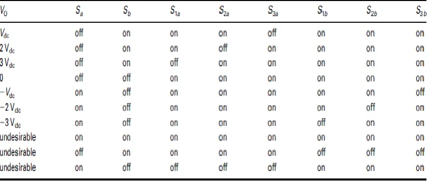
To introduce the operation of the proposed multilevel inverter in the generation of a desired output voltage waveform, a prototype seven-level CTRSI shown in Fig. 3 has been simulated using MATLAB/SIMULINK. If proper switching is used, then output voltage levels can be obtained between +3Vdc and -3Vdc. The maximum output voltage of this topology is 3Vdc. Table 1 shows the value of the output voltage VO in different modes of switching states. The input voltages of transformers by using this switching are shown in Fig. 3.
There are several modulation strategies for multilevel inverters and operation of them depends on modulation strategies. The modulation methods used in multilevel inverters can be classified according to switching frequency. In this paper, the fundamental frequency switching technique has been used. It is important to note that the calculation of optimal switching angles for different goals such as elimination of the selected harmonics and minimising THD are not the objective of this paper.
5. SIMULATION RESULT
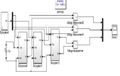
The model for single source cascaded transformer 15 level multilevel inverter for three phase has been successfully modeled and tested using MATLAB/SIMULINK toolbox. The performance is evaluated using FFT simulation.
Figure 1: Simulation model of cascaded transformer inverter
Figure2: Simulation model of sub system
Fig 3 Simulation Result of Single Cell Inverter
Fig 4 Simulation Result of Output of Trigger Level
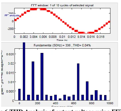
Fig 6 THD Analysis of output voltage using FFT analysis tool
6. CONCLUSION
In this paper, a novel topology has been presented for symmetrical multilevel inverter, which has reduced number of DC voltage sources and switches. Even though the use of transformers increases the design complexity and cost of the inverter, the proposed topology is simple and includes minimum number of components. The transformers can be used to isolation and voltage transformation. In the proposed topology, the PIV of all switches are equal with the Vdc.. Simulation and experimental results show performance and feasibility of the suggested topology in voltage generating.
7. REFERENCES
[1] Panagis, P., Stergiopolos, F., Marabeas, P., Manios, S.: ‘Comparison of state of the art multilevel inverters’. Proc. Power Electronics Specialists Conf. PESC 2008, IEEE, 2008, pp. 4296–4301
[2] Meynard, T.A., Foch, H., Forest, F., et al.: ‘Multicell converters: derived topologies’, IEEE Trans. Ind. Electron., 2002, 49, (5), pp. 978–987
[3]Du, Z., Tolbert, L.M., Ozpineci, B., Chiasson, J.N.: ‘Fundamental frequency switching strategies of a seven-level hybrid cascaded H-bridge multilevel inverter’, IEEE Trans. Power Electron., 2009, 24, (1), pp. 25–33 6
[4]Corzine, K.A., Familiant, Y.L.: ‘A new cascaded
multilevel H-bridgedrive’, IEEE Trans. Power
Electron., 2002, 17, pp. 125–131 Zhiguo, P., Peng, F.Z.: ‘Harmonics optimization of the voltage balancing control for multilevel converter/inverter systems’. Proc. IEEE 39th Annual Industry Applications Conf., 3–7 October 2004,vol. 4, pp. 2194–2201
[5]Nabae, A., Takahashi, I., Akagi, H.: ‘A new
neutral-point clamped PWM inverter’, IEEE Trans. Ind. Appl., 1981, IA-17, pp. 518–523
[6]Rodriguez, J., Lai, J.S., Peng, F.Z.: ‘Multilevel
inverter: a survey of topologies, controls, and applications’, IEEE Trans. Ind. Electron., 2002, 49, (4), pp. 724–738 Hammond, P.: ‘A new approach to enhance power quality for medium voltage ac drives’, IEEE Trans. Ind. Appl., 1997, 33, pp. 202– 208
[7]Cengelci, E., Sulistijo, S.U., Woom, B.O., Enjeti, P., Teodorescu, R., Blaabjerge, F.: ‘A new medium voltage PWM inverter topology for adjustable speed drives’. Proc. Conf. Rec. IEEE-IAS Annual Meeting, St. Louis, MO, October 1998, 1998, pp. 1416–1423