Genetic Algorithm Optimization for Microstrip Patch
Antenna Miniaturization
Mohammed Lamsalli*, Abdelouahab El Hamichi, Mohamed Boussouis, Naima A. Touhami, and Taj-eddin Elhamadi
Abstract—The miniaturization of the patch antenna has become an important issue in reducing the volume of entire communication system. This paper presents an improved method of size reduction of a microstrip antenna using the genetic algorithm. The shape of a typical rectangular patch is modified in order to reduce it resonance frequency keeping the physical volume of the antenna constant. Indeed, the initial patch is divided into 10×10 small uniform rectangles (Pixel), and the genetic algorithm searches, the optimal configuration for the desired goal. The resonance frequency of a micro-strip patch is shifted from 4.9 GHz to 2.16 GHz and a rate of miniaturization is up to 82%. To validate the procedure, an antenna prototype has been fabricated and tested with an FR4 substrate. The measurements results were in good agreement with simulation ones.
1. INTRODUCTION
Due to rapid decrease in size of personal communication devices, the size reduction of microstrip antennas is becoming an important design consideration. However, antenna design has grown more stringent and difficult over the years with inherent tradeoffs that exist between gain, radiation pattern, bandwidth, and physical size making antenna design a lengthy process.
Recently, several methods have been used to optimize patch antennas with varying success, such as using a dielectric substrate of high permittivity [1], Defected Microstrip Structure (DMS) [2], Defected Ground Structure (DGS) at the ground plane [3] or a combination of them, and various existing optimization algorithms such as particle swarm optimization (PSO) [4] and genetic algorithm [5–7]. The latter is one of the global optimization algorithms that have been used widely in the past by antenna designers for the optimization of the patch shape and size in order to achieve better overall performance of the antenna.
Genetic algorithm (GA) is a powerful optimization technique useful in a wide area of electromagnetics [8, 9]. It is based on the Darwinian concepts of natural selection and evolution. GA has been used to enhance the performance of microstrip patch antennas (MPAs) by optimizing the bandwidth, multi-frequency, directivity, gain, size [5–11] etc.
The concept of GA is to divide a regular square microstrip patch antenna into a grid of symmetrical squares and use genetic algorithms to selectively remove smaller metallic grid squares from the patch, and then, novel non-intuitive shapes can be produced. This method has been employed to create dual-band antennas because of several current paths on the patch, wide-band antennas, and longer meandering current paths on the patch lead to miniature performance of patch antennas. This paper is focused on a miniaturization procedure of rectangular patch antenna based on GA, by improving a cost function and using a uniform crossover technique. The typical shape of a rectangular patch is modified
Received 19 April 2016, Accepted 11 May 2016, Scheduled 29 May 2016
* Corresponding author: Mohammed Lamsalli ([email protected]).
into 10×10 small uniform rectangles (Pixel).
To validate the procedure, an antenna prototype has been fabricated and tested. Good agreement is obtained between theoretical and experimental results.
2. GENETIC ALGORITHM
The concept of the GA, first formalized by Holland and extended to functional optimization by De Jong, involves the use of optimization search strategies patterned after the Darwinian notion of natural selection and evolution [12].
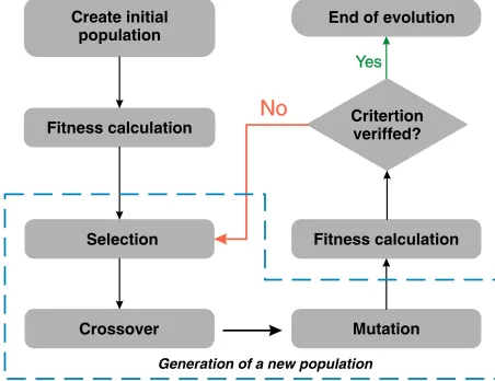
During a GA optimization, the parameters of each individual of the population are usually encoded as a string of bits (chromosomes). The first group of individuals (generation) is created randomly. The fitness of each individual is determined by the cost function. Mating these individuals forms a new generation. The more fit individuals are selected and given greater chance of reproducing. Crossover and mutation are used to allow global exploration of the cost function. The best individual may be passed unchanged to the next generation. This iterative process creates successive generations until a stop criterion is reached [13]. A block diagram of a simple genetic algorithm optimizer is presented in Figure 1.
Create initial population
Fitness calculation
End of evolution
Critertion veriffed?
Selection
Crossover
Fitness calculation
Mutation
Generation of a new population No
No
Yes Yes
Figure 1. Flow chart of the genetic algorithm optimization.
3. ANTENNA CONFIGURATION AND GA PROCEDURE 3.1. Microstrip Patch Antenna Configuration
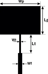
The first design of the proposed antenna is shown in Figure 2. In this design, a substrate FR4 is used as it is cheap and easy to fabricate. The substrate height is 1.6 mm, dielectric constant 4.3, and loss tangent 0.02. The antenna parameters are summarized in Table 1.
The simulated return loss obtained for this antenna is shown in Figure 3. We can see that the adaptation is better than 10 dB in a frequency band about 160 MHz, and the resonance frequency is around 4.9 GHz.
Table 1. Microstrip patch antenna parameters.
Parameters Wp Lp Lf Wf Lt Wt
Wp
Lp
Wt
Wf
Lt
Figure 2. Microstrip patch antenna configuration.
Figure 3. Simulated return loss of the patch antenna resonating at 4.9 GHz.
3.2. Genetic Algorithm Procedure
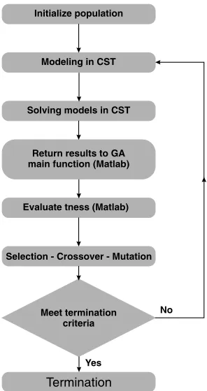
The patch area is divided inton×m cells. The conducting or non-conducting property of each cell is defined using binary encoding. If a cell is conducting, then the corresponding gene is assigned 1, and if a cell is non-conducting, it is assigned 0. The optimization procedure in our design is summarized as follows (Figure 4).
In other words, these steps may clear the previous figure:
Step 1: Create initial population by generating a random string of binary numbers.
Step 2: Create models according to the genes of individuals in population, set solving conditions and solve models in CST. Then return calculatedS11parameters to main function automatically (Matlab).
The returned parameterS11 will be called by fitness function (Matlab).
Step 3: Evaluate the fitness function. If the stopping criteria is satisfied then stop, else go to Step 4. The fitness function is the link between the physical problem and optimization procedure. The appropriate solution depends on the mathematical formulation of this function. Several researchers [13– 15] use the relationship (Equation (1)) to express the cost function. We notice that they take a large number of generations, and the algorithm converges from 40th or 50th generations.
cost=1 N
N
i=1
Q(fi)
(1)
where
Q(fi) =
|S11(fi)|, forS11−10 dB
+10 dB, forS11−10 dB
Modeling in CST
Solving models in CST
Return results to GA main function (Matlab)
Evaluate tness (Matlab)
Selection - Crossover - Mutation
Meet termination criteria
Termination
No
Yes
Figure 4. A block diagram of genetic algorithm function used in this design.
The fitness function is defined as:
cost= ⎧ ⎪ ⎪ ⎪ ⎨ ⎪ ⎪ ⎪ ⎩
|S11(fi)|exp −20
fres−fd fd
, forfd− < fi< fd−
1 N N i=1
S11(i)
, Otherwise
(2)
where
fi: Sampling frequency; N: Total sampling points; fd: Desired frequency;
fres: The individual resonance frequency;
S11: The S11(dB) parameter at resonance frequency.
= 0.1.
Step 4: Generate the next generation by applying the operator of Genetic Algorithm. • Selection: Roulette Wheel weighting;
• Crossover: Using the crossover operator at one point or two points requires a large number of generations. However, in this paper we use uniform crossover operator (Figure 5(a)) that allows a diversity of individuals, which leads to a significant acceleration of the convergence .
• Mutation: Random single bit (Figure 5(b)).
Figure 4 illustrates the crossover and mutation operation used in this paper.
Step 5: go to Step 2.
The problem of the previous designs is the presence of the 0 1
1 0
or 1 0
0 1
constellations, where
(a) (b)
Figure 5. (a) Uniform crossover operation. (b) Mutation operation.
(a) (b) (c)
Figure 6. (a) Traditional on/off building blocks with infinitesimal connections. (b) Proposed overlapping scheme. (c) A possible structure with overlapping.
between adjacent cells to avoid cells contacting each other by infinitesimal points and to ensure electrical contact in such constellations in the fabricated antenna. We must choose the minimum value of l0 in
order not to influence the structure. This value is limited by the precision of the production machine. In this design the sub-patches overlap byl0 = 0.1 mm. The principle of the overlapping element design
is shown in Figure 6.
4. RESULTS AND DISCUSSIONS
4.1. Resultant Microstrip Antenna with GA
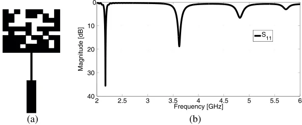
The GA algorithm is implanted into CST environment using Matlab. The starting antenna is divided into 10×10 cells, and an initial population of 20 individuals is generated using a random string of binary numbers. A random single point crossover method is used with a 100% probability of crossover. For the mutation operation, five bits at maximum are randomly chosen for each individual. The convergence is obtained after 14th generation.
(a)
2 2.5 3 3.5 4 4.5 5 5.5 6
40 30 20 10 0
Magnitude [dB]
Frequency [GHz]
S11
(b)
carefully in this paper. When there are several current paths on the patch, MPAs show multiband performance and longer meandering current paths on the patch lead to miniaturization performance. Our objective is to have the maximum rate of size reduction. In this paper, we will be focused on the resonance frequency that is shifted from 4.9 GHz to 2.16 GHz.
4.2. Fabrication and Measurement
The designed antenna structure is fabricated and tested in our laboratory with CNC machine (LPKF S63). Shown in Figure 8(a) is the size of the fabricated microstrip antenna that operates at 2.16 GHz. In order to measure the scattering parameters of the proposed antenna, we employ a Rohde and Schwarz ZVB 20 vector network analyzer, whose frequency range is limited to 20 GHz.
The S11 parameter was measured and compared to the simulated results. Figure 8(b) shows the
comparison between measurement and simulation results of the microstrip patch antenna with GA. The practical results are found to be well consistent with the simulated ones. However, some discrepancies have occurred, due to the fabrication inaccuracy and conditions of measurement.
(a)
2 2.5 3 3.5 4 4.5 5 5.5
-20 -15 -10 -5 0 5
Magnitude [dB]
Frequency [GHz] S
11 Measured
S
11 Simulated
(b)
Figure 8. (a) Prototype of optimized microstrip antenna (b) Measurement and simulation results for the optimized antenna (resonating at 2.16 GHz).
4.3. Comparison between Conventional and Optimized Antenna
4.3.1. Size Comparison
Figure 9 shows a size comparison between a conventional microstrip antenna and the optimized antenna with GA, both resonating at 2.16 GHz. We can see that the patch size, compared with the conventional one, is reduced by 82%.
42
31.3
17.58
12.29
4.3.2. Radiation Pattern
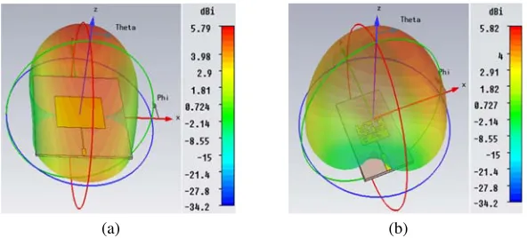
One of the problems in microstrip antenna applications is to reduce the size while keeping good performance. From Figure 10 we can see that the simulated gain for the conventional antenna is around 5.79 dBi, and for the optimized antenna with GA is around 5.82 dBi. We conclude that with GA we can reduce the size keeping important gain compared with the conventional antenna. The gain comparisons of the optimized antenna with other recently developed antennas are shown in Table 2. The optimized antenna presents a good gain feature.
(a) (b)
Figure 10. Radiation pattern at 2.16 GHz (a) conventional antenna. (b) miniaturized antenna.
Table 2. Comparison between recently proposed antennas and this antenna.
Antenna Methods Rate of miniaturization Gain (dB)
This work Genetic Algorithms 82% 5.82
[2] Defected Microstrip Structure 72% 4.12
[3] Defected Ground Structure 50% 2.14
4.3.3. Current Distribution
Figures 11(a) and 11(b) show the current distributions of conventional and optimized patch antennas with GA at 2.16 GHz. It can be seen that in conventional antenna, a large surface current is observed over the superior and inferior parts of the patch antenna (Figure 11(a)). However, in the optimized patch antenna with GA, the current is more concentrated along the coins of the patch (Figure 11(b)). Therefore, the current distribution of the patch antenna, resulting in a controlled excitation and propagation of the electromagnetic waves, changes the resonance peak to a lower one.
(a) (b)
Genetic algorithm optimization of the parameters of a rectangular patch antenna and performance analysis using the CST software has been carried out. In the developed antenna, the surface current path is meandered, and hence the electrical length of antenna is increased. This means that for an antenna with the same resonance frequency, the overall surface is decreased to a great amount. In this way, patch size reduction up to 82% has been achieved with a radiation pattern typical of our microstrip patch antenna compared with a conventional one resonating at the same frequency.
REFERENCES
1. Lo, T. K. and Y. Hwang, “Microstrip antennas of very high permittivity for personal communications,”Asia Pacific Microwave Conference, Vol. 1, 253–256, 1997.
2. Elftouh, H., N. A. Touhami, and M. Aghoutane, “Miniaturized microstrip patch antenna with spiral defected microstrip structure,”Progress In Electromagnetics Research Letters, Vol. 53, 77–44, 2015. 3. Elftouh, H., N. A. Touhami, M. Aghoutane, S. El Amrani, A. Tazon, and M. Boussouis, “Minia-turized microstrip patch antenna with defected ground structure,” Progress In Electromagnetics Research C, Vol. 55, 25–33, 2014.
4. Lee, K. C. and J.-Y. Jhang, “Application of particle swarm algorithm to the optimization of unequally spaced antenna arrays,” Journal of Electromagnetic Waves and Applications, Vol. 20, No. 14, 2001–2012, 2012.
5. Soontornpipit, P., C. M. Furse, and Y. C. Chung, “Miniaturized biocompatible microstrip antenna using genetic algorithms,” IEEE Trans. Antennas Propag., Vol. 53, No. 6, 1939–1945, 2005. 6. Herscovici, N., M. F. Osorio, and C. Peixeiro, “Miniaturization of rectangular microstrip patches
using genetic algorithms,” IEEE Antennas Wirel. Propag. Lett., Vol. 1, No. 1, 94–97, 2002. 7. Jayasinghe, J. W. and D. N. Uduwawala, “A novel miniature multi-frequency broadband patch
antenna for WLAN applications,” 8th IEEE Int. Conf. Ind. Inf. Syst., 361–363, Peradeniya, December 2013.
8. Johnson, J. M. and Y. Rahmat-Samii, “Genetic algorithms in engineering elecromagnetics,” IEEE Trans. Antennas Propag., Vol. 39, No. 10, 7–21, 1997.
9. Weile, D. S. and E. Michielssen, “Genetic algorithm optimization applied to electromagnetics: A review,”IEEE Trans. Antennas Propag., Vol. 45, No. 3, 343–353, 1997.
10. Jayasinghe, J. M. J. W. and D. N. Uduwawala, “A broadband triple-frequency patch antenna for WLAN applications using genetic algorithm optimization,” 7th IEEE Int. Conf. Ind. Inf. Syst. (ICIIS), 1–4, Chennai, August 1986.
11. Jayasinghe, J. M. J. W., J. Anguera, and D. N. Uduwawala, “Genetic algorithm optimization of a high-directivity microstrip patch antenna having a rectangular profile,”Radioengineering, Vol. 22, No. 3, 1–4, 2012.
12. Haupt, R. L. and S. E. Haupt,Practical Genetic Algorithms,, John Wiley, 2004.
13. Johnson, J. M. and Y. Rahmat-Samii, “Genetic algorithms and method of moments (GA/MOM) for the design of integrated antennas,”IEEE Trans. Antennas Propag., Vol. 47, No. 10, 1606–1614, 1999.
14. Jayasinghe, J., J. Anguera, and D. Uduwawala, “On the behavior of several fitness functions for genetically optimized microstrip antennas,” Int. J. Sci. World, Vol. 3, No. 1, 53–58, 1999.
15. Su, D. Y., D. M. Fu, and D. Yu, “Genetic algorithms and method of moments moments for the design of pifas,”Progress In Electromagnetics Research Letters, Vol. 1, 9–18, 2008.
16. Jayasinghe, J. W., J. Anguera, and D. N. Uduwawala, “A high-directivity microstrip patch antenna design by using genetic algorithm optimization,”Progress In Electromagnetics Research C, Vol. 37, 131–144, 1986.