The
Connection Machine System
CMoS
Field Service Guide
Preliminary
OCI~er 9, 1992'
.
The
Connection Machine System
CM-S
Field Service Guide
Preliminary
October 9, 1992First printing, July, 1992
The inrormation in this document is subject 10 change without notice and should not be construed as acommit-mcnt by Thinking Machines Corporation. Thinking Machines Corporation reserves the right to make changes to any products described herein 10 improve functioning or design. Although the infonm\lion in this documer.t has been rcyiewed MId is believed to be rcliable, Thinking Machines Corporation cloes notlUsumc responsibility or liability for any erroR that may appear in this documenL Thinking Machines Corporation does not assume any liability arising from the application or usc of any informuion or product described hercin .
••••••••••••••••••••••••••••••••••••••••••••••••••••••••••••••••••••••••••••••
Connection MachineC is • registered trademark of Thinking Machines Corporation.
CM, CM-1. CM·2, CM·2oo, C.M·5. and DataVault arc uademarks of Thinking MJChinc$ Corporation. CMosT and Prism are trademarU of Thinking Machines Corporation.
C·,z is a registered trademark of llUnking Machines Corporation.
Paris. -Lisp. and CM FOTtran are trademarks of Thinking Machine.s Corporalion. CMMO. CMSSL. and CMXt\ arc trademarks of Thinking Machines Corporation. Scalable Computing (sq is. lIadcmark of Thinking Machines COJporation. Thinking Machines is a trademark ofThnking Machines Corporation. SPARC and SI'ARCstation arc trademarks of SPARC International. Inc. Sun, Sun·4. and Sun Workstation arc trademarks of Sun Mierosystems, Inc. UNIX is a registered trademark of UNIX System Laboratories. Inc.
The X Window System is a trademark of the Massac::,usetlS Institute of Technology.
CopyriGht 0 1992 by Thlnking M""htnes Corpor.ticn. All rights reserved. Thinking Machine5 Corporation
24S First Street
Contents
Chapter
1 Introduction
...
..
..•..•....•...
1.1 Purpose ...•..•..•....•...1.2 General Troubleshooting Practices ...•..•....•..•... 2
1.3 Summary of Diagnostic Tools ...•..• , . . . • . . . . 4
Chapter 2 Troubleshooting Fundamentals
. .. ... .
.
..•. ...
.
. .•. .
.. .. ..
..
5
Chapter 3 Preventive Maintenance
3.1 Summary ...•..•...•..•....•..•...,
9 3.2 Daily Preventive Maintenance ... . . . .. .•. .•.. .. . . .•. .•. . .. • . .•. . . .. 113.2.1 Initial COfIditions ...•..•...•..•...••..•.. 17
3.2.2 Diagnostic Procedure 11 3.3 Weekly Preventive Maintenance.. . .. . . . . . .. .•. . .. ...•. .•. . . .. 19
3.3.1 Initial Conditions ... 19
3.3.2 Weekly Test Proccdl.fC with No
I/O. . . .. .
.•. . .
. .
. .
•
. .•
. .
. ..
193.3.3 Weekly Test Procedure with ItO . ... .. .. . .•. . . . .. .•. . . . .... 22
C
hapter
4 System
Sta
rtup
and
Shutdow
n
_..
....
....
..
...
..
..
.... 2'
4.1 System Startup ...•... 34
4.1.1 Boot External Control Processors. . . • . . . • . . . .. 34
4.1.2 Power Up All Peripherals ... 34
4.1.3 Power Up (he CM ... 34
4.1.4 Log in to the System Administration Console ... 40
4.1.5 Update hardwarc.insull if Hardware Has Changed. . . .. 40
4.1.6 Update io.conf if I/O Bus Configuration Has Changed. . . .. 40
4.1.7 Sct Environment Variables ... 40
4.1.8 Check the Current Partitioning State ... 41
4.1.9 Bringing up a System - Examplc... ... 41
4.1.10 Create User Panitions ...•... _ ... 45 4.1.11 RcsetthcCM ...•... 45
"
CM·5 Field Service Gllidc-Preliminary
4.1.12 Activate Partitions ...•..•..•..•...•...•... 45
4.1.13 Initialize the I/O System ...•... 45
4.2 System Shutdown. ... .. ... .. ... .. ... . . ... . . ..•..•. . . .. . .•.. .. ... 47
4.2.1 Stop All Timesharing Daemons. ... . . ... ... .. . . .•.. . . ... 47
4.2.2 Delete All Partitions ... . . • . . . .. 47
4.2.3 Shut Down External Control Processors ...•... 47
4.2.4 Power Down the CM·S . . . .. ... .. .. . . .. .. . . . .•• . .. . . .. 48
4.2.5 Shut Down All Peripherals. . . .. 49
Chapter
5
eM
Error Logging System
...
.
.
.
...
..
...
51
5.1 Implementing
eM
Error Logging ... 515.2 Error Message Description ... , .. , . . • . . . 52
Appendix
A
Investigating ts-daemon
Failures
with kpndbx
...
.
...•..•...
53
Appendix
B
Generating Eno.
Information
. . .
... . .
... .. . . .
•. . •.. .
. .
. ...
57
B.1 Running cmdiag within a Partition. . . •. . . • . . . . .. 62
B.2 Running cmdiag on the Full System ...•...•... 63
Appendix C
Failures at
the Leaf
Node Level ..
...•..•...•...
67
C.I Overview... 67
C.2 PN Board Replaccment Procedure. . . • . . • . . . • . . . . .. 67
Appendix 0 Tracing Control Network Errors. . .
.
.
. .
.
..
.
. . .. .
. .
•. . . . ..
69
D. J Introduction... 69
0.2 Fault Isolation Procedure ...•... 70
Appendix E Tracing Data Network Errors ...
.
..
.
...
.
, . . . . ..
71)
Appendix F I/O Diagnostic Tools. ...
.. . .•..•. ... .. .
•. . •..•. . .. .
. .
.. . . . ..
83
EI Introduction... 83
E2 IOBA Internal Diagnostics ...•... , .. , .. , . . • . . . .. 87
F.2.1 IOCLK (JTAG) ...•..•... " . . . • . . • . . . .. 89
Conrents
F.2.2 IODR (JTAG) ...•. . . •. . • . . • . . . .. 89
F.2.3 IOCNTRL (JTAG) ... _ .. _ .. _.. . . .. 89
F.2A IOBUF (JTAG) _ .... _ ... _ ...•..•. _ • _ . _ .. 89
F.2.5 IOCHNL (HAG) ... 89
F.2.6 IOP-CNTRL (Functional) . . . • . . . .. . . • . . . . • .. . . .. . . 89
F.2.7 IOP-BUF (Functional) ... 90
F.2.8 IOP-CI-n~L (Functional) . . . • . . . • . . • . . . 90
F.2.9 IOP-SYS (Functiona\) .. . .. .. . . ... .•. ... . . .. . 91
F.3 eM-Based Verifiers ...•..•... 91
F.3.1 Focused CM-to-DamVault Verifiers... 92
F.3.2 End-to-End Tcsts . ' . . . •. . • . . . 93
F.3.3 dvtest5 ... ... , •..•... _ ... 101
F.3A hippi-loop5 ... . . . . .. . .. ... . . ... . •. .•. . . 110
FA DataVaulllnternai Diagnostics ...•...•..•... , . III FA.! Complete Test Suite ... 112
FA.2 Functional Tcst Groups ...•... _ ...•..•.... , ... 112 F,4.3 Invoking Individllal Tests ... , ..•... , ..•... 113
F,5 CM-IOPG Internal Diagnostics .. 114
F,6 CM·IOPG Verifiers.. . . .. . .. . .. _ ... , . .•. . . ... .•. .•. . . .. . 116
F.6.1 serial ... ,... 116
F,6.2 TapcDVxfervfr ... ...•..•... 116
F. 7 DM-HlPP! Internal Diagnostics . . . • . . • . . . .. lIS F.7.l Source Board Functional Test... . •... ll8 F,7.2 Destination Board Functional Test ... 119
F,7.3 JOP Board Functional Test ... 119 F,7A System (Loopback) Test ... 120
Appendix G Troubleshooting Power
S
upply,
Clock, and Diagnostic Network
Fau
lt
s
...
,
..•...
121 GJ Introduction ... _ ...•... 121Appendix
H Tracing
I/O Errors ... .
H.I Introduction ... , ...•...•... 12J 123 H.2 Basic 110 Troubleshooting Procedure ...•...•... 123H.3 Verifying IOBA-to-DataVault Path ... ,... 124
H,4 System Verifiers for Data Vault and HlPP! Paths ...•...•... 124
,i CM-5 Field Service Guide-Preliminary
Appendix I
hardware.install file
...•..•..•...•... 125
1.1 Introduction... ... . . . .. 1251.2 File Header (shaded area I) ...•...•..•..•...•...
1.3 eM System (shaded area 2) ...•..•..•...•... 1.4 Sysrem Name (shaded area 3)
1.5 DR Height (shaded area 4) ... .
1.6 PN Type (shaded area 5) ... , ...•..•...•...
1.7 Partition Managers (shaded area 6)
129 129 129
129
130
130
1.8 PN Cabinet 0 (shaded area 7) . . . .. . ...•...•... 131 1.9 PN Cabinet I (shaded area 8) . . . .•. .•. .•. . . ... .. . .•. . . 134
1.9.1 PN Bacl.;plane 3 ...•...•..•..•... 134 1.9.2 I/O Backplane 7 ... 135 1.9.3
1.9.4
DR Backplane &-9 CN Backplane 10
. . . • . . • . . . .. 137 131 1.10 DR Cabinet (shaded area 9) ... 138
Appe
n
d
i
x J
i
o.conf file
...
...
.
... 14
1 J.I The Channcl_Board_Configumion Module ...•... 144 J.2 The IO_device_configuration Module ...•..•... 145Appendix K Error Reporting System ...
.
... 147
K.I Overview ... . 147 148 148
I
SO
K.2 Interpreting Error System Reports ...•..•...K.2.1 Control Network Error Example ...•..•... K.2.2 Data Network Error Example ... ...•..•...
Appendix
L dvtcstS Description
....
.
.
.
...
.
...
.
.
... 151
Appendix
M Man Pages
...
..
...
.
... 1
57
Chapter 1
Introduction
mi
WW:
j
M
f
RiMed§8 HH
1.1 Purpose
The primary intent of this manual is to help you troubleshoot hardware problems
in a CMoS
system.
Itconta
i
ns a
v
ariety of
infonnation
[
or this
purpose, including:
descriptions of the system hardwarv, a description of the error reponing system, descriptions of the diagnostic tools provided for troubleshooting h::miware faults, and recommended diagnostic procedures.How you use this manual will largely depend on how experienced you arc with CMoS
syste
m
s
.
• If you arc new to the CMoS and its diagnostic software environment,
emdiag. you should read through the
entire
manual at least once beforeyou have occasion to usc it. Then, when a troubleshooting situation arises, follow the basic troubleshooting procedure described in Section 2. This proccdure will get you through the initial diagnostic SICPS and will guide you in using other sections of the manual as the panicular troubleshooting session requires.
• If you have a good understanding of the systcm arehitecture and experi-ence using cmdiag. you can treat this document as a reference manual, consulting it only for specific details.
NOTE: This manual assumes that you have received fonnal training on CMoS sys-tem administration and maintenance issues. It does not provide comprehensive documentation of these topiCS.
2 CMoS Field Service Guide-Preliminary
1
.
2 General Troubleshooting Practices
The practices listed below have been found 10 promote more efficient trouble-shooting in virtually all situations. They either simplify the troubleshooting task or they help avoid introducing new problems as old ones arc investigated.
1. Gather initial information. - Before taking any active diagnostic steps, gather as much infonnalion aboutlhc Cailure as possible. Some
q
ues
t
io
n
s th
a
I o
f
te
n
uneo
·
.c
r
u
se
ful
c
l
ues arc
li
ste
d
below.• If the failure occurred while running a uscrprogralTI, ask iflhc
pro-gr
am h
as
ru
n success
f
u
ll
y o
n th
is
CMoSbc:fore.
If
so,
h
as
th
e 0.,1
changed in any way since then? If the answer is yes 10 these ques-ti
ons, f
md
o
ut
w
h
at ch
an
ges
ithas unde
r
gone
since
t
he
p
rogmm last
r
an s
u
ccessfu
lly.
• Has the user program run successfully on a different partition of this CM? If the answer is yes, focus attention on the hardware asso-ciated with the failing partition_
• Likewise, has the program run successfully on another CM-5 sys-tem? If so, is that system different in any way - sofLware version, hardware configuration, ECO levels, ere? If yes, consider the impli -cations of those differences.
• Have any other programs run successfully on Ule same
eM
pani-tion? If yes, examine the differences between Ule successful and un-successful programs. For example, are the memory requirements of one program significmtly different than the oUler'!2. Check for simple solutions first.- Check the obvious conditions, such as power supply or COOling fan failure. While these ,becks seldom lead to an immediate fix, they will avoid unnecessary troubleshooting time and effon on those few occasions when the solution is simple.
3. Change as little as possible. - Every modification to hardware has the inherent risk. that it will introduce a new problem. When changes are unavoidable, try to adhere to the following guidelines:
• Change one thing at a time and record all changes.
• When you make a change that does not fix the problem. undo the change before progressing to the next step, particularly if that step involves making another change.
Chapler 1. {nrrQduction 3
lffi :: :: S :,::
• If diagnostic messages point to a specific circuit board, check the board's scating before replacing it. Poor electrical contact caused by contaminated edge connectors or by inadequate scaling is a com· mon cause of faulty perfonnance. Reseating a circuit board will help clean the metal surfaces and re-establish solid contact. After reseating a board, retest to see if the fault was corrected.
4. Swap boards berore changing cables. - Use board swapping for fault isolation before changing cable connections. In a system that has been running successfully, cablc faullS arc much less likely than component or board failures. In addition, disconnecting and reconnecting cables poses more risk of causing a new problem than replacing circuit boards. 5. For intermittent problems, increase the length of test runs to stress
the hardware being tested.
6. ALWAYS WEAR ANTI-STATIC PROTECTION WHEN HANDL·
ING
CIRCllT
BOARDS. STORE BOARDS
I
N
ANTI·STATIC
BAGS.
4 CM-5 Field Service Cuide-Preliminary
1.3 Summary of Diagnostic Tools
Various diagnostic tools are provided for troubleshooting hardw;lrc failures on
the
eM.
The fonowing list summarizes lhese tools and indicates where you can find explanations of their use.• Use kpndb:z to investigate Processing Node failures. ll1C procedure for using kpndbx is described in Appendix A. Its man page is provided in
Appendix M.
• The primary diagnostic 1001 for investigating hardware (;lulls in the CM-5
is crndiag. Its use is described in Appendix. D. The crndiag man page is in Appendix M.
• A subset of crndiag tests target IOBA hardware. These tcsLS arc
aug-mented by several indcpcnd:Ol test packages, which exercise the different
I/O devices and Iheir interconnecting hardware. The various I/O-related diagnostic tools arc described in Appendix F.
• A number of system verifiers are available for exercising the eM across
functional boundaries. These provide comprehensive coverage of system
functions by closcly emulating the behavior of user applications. These
verifiers arc described in Appendix
H.
C
h
a
pt
e
r
2
Troubleshooting Fundamental
s
Often. the initial stage of a troubleshooting session - deciding what action to
take first - can be the most difficult. This chapter offers a brief set of guidelines
for dealing with this early phase.
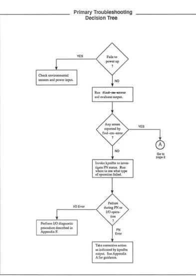
The steps presented below offer a rational opening strategy for troubleshooting CM-5 hardware faults, regardless of the source of the failure. Figure 1 illustrates
the key JXlints in this procedure.
NOTE: As a matter of convenience. you can have cmdJ .. ag running on the full
system at all times. This cmdiaq would not be associated with any individual partition (j.e .• it would not be invoked with !he -p option) and would therefore nOt interfere with timesharing daemons running on partitions. Appendix M con-tains the cmcUag man page.
1. If cmdiag is not already running, invoke it on the entire
eM
(do not uscthe -p option).
2. Run find-em-error. Sec Appendix K for a deSCription of find-em-error output.
3. The next step depends on what find-em-error reports.
October 9,1992
• If no errors are reponed, the problem may be in a Processing Node or in an area of I/O hardware that is not accessible to the diagnostic network. In either case, PN registers may provide useful Status in
-formation. Run kpndbx to read PN status. Appendix A describes the kpndbx procedure.
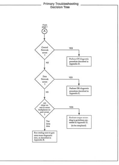
• If Control Network errors are reponed, usc the troubleshooting pro· cedure described in Appendix 0, Traeing Control Network Errors.
6 CM·5 Field Service Guide - Preliminary
;w &""
• If Data Network errors arc reponed, usc the troubleshooting proce-dure described in Appendix E, Tracing Data Network Errors.
• If find-em-error points to I/O hardware, usc the troubleshooting tools described in Appendix: F.
If all chips on a backplane or on multiple backplanes I'CfXln errors, the source of !.he problem can be a faulty power supply, system clock, or diagnostic network. Appendix G describes the procedure for troubleshooting symptoms of this kind.
Chapter
2.
Troubleshooting FundamentalsOC/ober 9,1992
o.eck cnvitonrncnW
Primary TroubleshOOting Decision Tree
F&iIo to
...
,
""'lOtS In<! power itll"'~ NO
Paf""" I/O di'8I'",tic
p ... Uf1l d . . . ribod itI API""'di~ F.
110 ErlQr
Run
.
1a4_ ...
n • • M CV.1UIle<'U'I"'LFlU ... dorin, PN 0.
1.0..,.... •
..
.
,
"
,,~
T ... ~~vlloUon
II itldicoUICI b,. kpnclb>. adjU. s.",A~ Ar"'lI'id..-.
Figure I. Strategy for initial phase of troubleshooting session. (\ of 2)
8 eM·5 Field Service Guide-Prelimin.ary
,
Primary Troubleshooting Decision Tree
A>
clllp<on ""eot more
b>okplon .. ~ ~"-
,
,~
hltle
".
Run crru!U&
",>t
.
Lo aen-en", m"'" diagn<><ticd ... described in
AppcndUc D.
'"
P<.Ir.,.,,,, eN d;'S-'''''''' procedu .. described in Appendil. O.
'"
i'<:d'orm DR diagnostic
pmcedure del;cri~ in Append;' E.
Enh ... "'''f''" '«>0<_
din, \0 guideline.< 1''''' .... led in Al'!""'di. G.
(10 be completed)
Figure L SLralcgy for initial phase of troubleshooting session. (20[2)
C
h
a
pt
e
r
3
Pre
v
entive Maintenance
3.1 Summary
The CM-5 preventive maintenance program is intended to expose incipient hard-ware faults in a controlled sclting, reducing the likelihood of failures occurring while user code is executing. There are two schedules in the CMoS preventive
maintenance
program
-
a
shon.,
less
comprehensive daily routine and a
long
e
r.
more rigorous wccldy procedure.
• The daily routine implements the Processing Node test group, the Data Network. verifier group, and the Control Network verifier group. This
pro-cedure
i
s
illustra
t
ed
inFigure
2;
de
t
ailed descripti
o
n
s
of each
step
arc
pro-vided in Scction 3.2 and are cross-referenced in the margin of Figure 2.
• The weekly program involves nmning the JTAG tests in addition to the daily test groups. Figure 3 illustrates this procedure in transcript fonn with cross references to detailed descriptions in Section 3.2.2.
If the system includes I/O hardware, scveralllO tests provided by cmdiag
arc added to the weekly regimen. This expanded procedure is illustrated in Figure 4 with cross references to detailed descriptions in Section 3.3.3.
NOTE: Currently, the weekly maintenance procedure is not compatible with uscr partitions and. so, requires exclusive usc of the system.
cmdiag includes an interface to the cmpartition software. This interface
al-lows you to usc the high-level etr;Iartition functions to restrict the scope of
cmdiag to a subset of the system hardware. Tests run within that partition will
not interfere with user applications running in other partitions.
10 CM-5 Field Service Gljide-PreiiminoT)
Daily PM Procedure
Introductory NOlQS
The system used to ilIusU<l\e lhis procedure cxtlmple has lhe rallowing :ulributcs. -System is named Calliope and has 256 PNs.
- Diagnostic server is named homer. think. com.
- Calliope has two 128-PN partitions. which are allocated 10 p;lI'tilion managers named virgil.. think. com and milton. think. com.
- Diagnostics will be run on virgil.. tbink. com..
login: llSu_id
•
••
pass .... ord: r()()f.yassword
SU homer. think. com /dev/console hom' cd /uar/diag/cmdiag
2 hom' •• tanv CMDIAG_PATH /uar/diaq/cmdiag hom' •• tanv JlAG_SERVER ho ... r.think.com
3 hom' /u.r/.tc/~rtition Ii.t -1
eM System "Calliope"
256 Processors ( 8 Mbytes rremory, SPARe lU, SPARe FPU I 2 Partition Managers
virgil.think.com milton. think. com Availabl. PH Ranges:
All PNs in use lOP Add,ra""a"
.80
Name V128 Ml ,,~
Partition Manager virqi1.think.com miltnn.think.cnm
Si2e State 12e ACTIVE
12~ ACTTW.
4 hom' r10qin -1 root virqil.think.eoll\ pas:sword: QuiViv.
Nodes 0-127 12R-255 480-460
virq' a.t.nv CKOIAC_PATH /uar/diaq/emdiaq virgl a.t.nv JTAC_SERVER hOm<Or.think.cOfll virg' empartition atop -pm virqil.think.com
(continued on next page)
Oe:scription virqi1 miltnn
Figure 2. Daily preventive maintenance - I of 2
Chapter 3. Preventive Maintenance
Daily PM Procedure
(continued from previous page)
5 virgf cmpartition list -1 CM System "CalliopeN
256 Processors [ 8 Mbytes memory, SPARC IU, SPARe FPU I
2 Partition Managers virgil.think.eom
milton. think. com Available PN Ranges:
All PNs in use
lOP Addresses
480
Name V128 M128
Partition Manager
virgil. think. com
milton.think.eom
Size State Nodes
128 ALLOCATED 0-127
128 ACTIVE 128-255
480-480
6 virgf cmdiag -C -p virgil.think.eom
Description virgil milton
<CM-DrAG> rgroupa m PH global broade.at combine dr partition
; diagnostic test report
NOTE
When the partition managed by milton becomes available for tcsting, rcpeat steps 41.hrough 6 on milton.
Figure 2. Daily prc\'cnth'e maintenance - 2 of 2.
OClOber 9,1992
12 CM-5 Fidd Service Guidc-Prdiminary
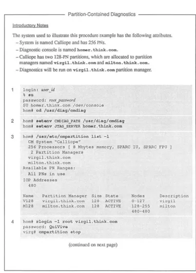
Weekly PM without VO
Introductory Noles
The system used to illuslIale this procedure example has the following attributcs. - System is named Calliope aod has 256 PNs.
- Diagnostic server is named hOlMr. think. com.
- Calliope has two 128-PN partitions, which are allocated to partition managers named virQil. think. com and milton. think. com.
- Diagnostics will be run on bomar. think. eo ..
login: u.ser _id
• ou
pas8wQt'd: fOOlyassword
SU homer.think.eom {dey/console
hom' cd /uar/diagfcmdiag
2 hom' •• t.nv omuc PA'rH /uar/diag/cmd.ia9
hom' •• t:...,v JTAG SERVER homor. think. COlli
3 hom' /uar/etc/cmpartition li.at -1 eM System ~Calliope~
256 Processors [ 8 Mbyces ~emory, SPARe IU, SPARe
,PU I
2 Partition Managersvirgil.think.com milton. think. com Available PN Ranges:
All PN, in volle
lOP Addrasa,u
480
Name V128 M120
Partition Manager virgil.think.com milton.think.com
Size State
126 ACTIVE 126 l'ILLOCAT!:O
4 hom' rloqin -1 root virqil.think.com
password: QuiViv.
virg' a.t.nv CMOIAG PATH /uar/diaq/cmdiaq
virg. a.t.nv .nAG_SZRVEI!. hOlllilr.think.com virq' cmpartition atop
virq' cmpartition del.t.
virq' exit
(continued on next page) Nodes 0-121 128-255 480-480 Description virqil milton
Figure 3. Weekly maintenance with no I/O - 1
nr
2Chapler 3. Preventive Maintenance
Weekly PM wilhoul
va
(continued from previous page)4 hom' cmpartition delata -pm milton.think.eom (COni.)
5
hom' ¢#partition list-1
eM SY'5tem "Calliope"256 Processors ( 8 Mbytes rremory. SPARe IU. SPARe FPU 1 2 Partition Manager5
6,7
virgil.think.eom
milton. think. com Available PN Range5:
All PN5 in U5e lOP Addre5"e'5
480
hom' ./cmd.iag"
-c
<CM-DIAG> rqro\lps <CM-DIAG> rqrO\lps <CM-DIAG> rgroups <CM-DIAG> rqrO\lps <CM-DIAG> rgroups <CM-DIAG> rqro\lps <eM-DIAG> rqroupll <eM-DrAG> rgroups•
"""
•
'~N•
,=w
III SPI III FILLER III PI'. PEHEHm ON
.OR
8 eM-DIM> q
; diagnostic test rcpon
hom' /\lsr/etc/cmpartition craate -pn_rangQ 0-255
9 hom' """"" ••• t
hom' = . s e t -.
homt ./cmd.i&q -C -p hOlllQr.think.cOlll
<eM-DrAG> rqroupll m PN dr combine global broadcast partition
Figure 3, Weekly maintenance with no I/O - 2 of 2.
October 9,1992
14 CMoS Field Service Guide-Preliminary
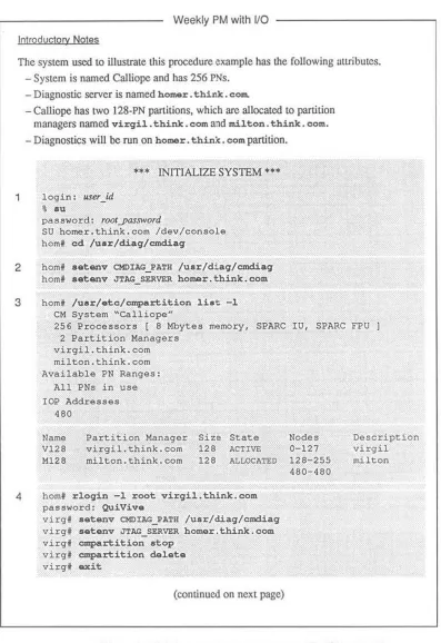
Weekly PM with lIO
-tntroductory Noles
The system used to illustrate this procedure e)(ample has the following <It1ributcs. - System is named Calliope and has 256 PNs.
_ Diagnostic server is named hamez:. thiflk. c::om.
- Calliope has two 128-PN partitions, which arc allocated to partition managers named virqil. think. c:om and miH.on. think. eom.
- Diagnostics will be run on homer. thi.nlr:. eam partition.
login: usu_id
•
.u
""*
INITIALIZE SYSTEM ...password: rootyassword
SU homer. think. com /dev/console
hom' cd /uar/diaq/cmdiag
2 hom' •• tanv CMOIAG_PATH luar/diaq/cmd.iaq
hom' •• tanv J'l'AG_SERVER homer.think.eom
3 hom' /uar/etc/cmpartition liat -1
eM System "calliope"
256 Processors [ B Mbytes memory, SPARe 1U, SPARe FPU J
2 Partition Managers virgil.think.oom
milton. think. com
Available PN Ranges: All PNs in use lOP Addresses
'SO
Name
V128 Ml28
Partition Manager virgil. think. com
milton. think. com
Size State
128 ACTIve
128 ALLOCATED
4 homf rlogin -1 root virgil.think.com
password: QuiVive
virg' .atanv CHDIAG_PATH /u.r/diaq/cmdiaq
virgf aetanv JTAG_SERVER homer.think.com
virgf cmpartition .top
virg. cmpartition delete
virg' cu::it
(continued on next page) Nodes 0-127 128-255 480-480 Description virgil milton
Figure 4, Weekly pre\'entive maintenance with VO - I of 3
Chap/u J, Preventive Maintenance
Weekly PM with
va
(continued from previous page)4 hom' :1o.q1.n -1 lII.il.to.n.think.cOlll
(cont.) pauword: QulVaLa
milt • • • t.nv CMDUG_PA'lH /uar/diaq/emdiaq milt • • • tenv J'J'AG_SZRVU; ho.mer,thlnk.oOlll
milt' ~~lt1.o.n del.t.
milt' N:lt
5 hom' ~a~1.tlon li.t -1
eM System ~Calliopau
6,7
B.9
256 Processors [ B Mbytes memory, SPARe 1U, SPARe FPU J
2 Partition Managers
virgil.think.com milton.think.com Available PN Ranges:
All PHs in ulle
lOP Addrells8s
480
... RUNCOMPLETEJTAG TESTS •••
hom' ./CIIId.i&q-C <eM-DIAG> rql:Coupa III
; diagnostic test report
••• TEST DATAVAULTS •••
dvloqin:~r_jd
password: rOOly<Usword
dv' /uar/local/atc//diag/dvcoldboot +cn
dv' /uar/local/atc/diag/diagsarvel:C/diaqaerver ,
(continued on next page)
Figure 4. Weekly prel'cmh'e maintenance with I/O - 2 or J
October 9,1992
16 CM-5 Field Service Guide-Preliminary
''''''
Weekly PM with 110
(continued from previous page)
; diagnostic test
rcpon
<CM-DI~G> ~eut.-all-ioppo-t •• t.
; diagnostic test report
••• TEST eM-HIPP! & CM-IOPG
***
15-18 <eM-OIAG> t •• t-cmio-d.vic.-dat&-xf.~; diagnostic report
010 . . . RUN PN & NETWORK TESTS ON SYSTEM-WIDE PARTITION
***
19-21 <eM-OIAG> q
hom' juarjetc/partltion create -pn_rang8 0-255
hom' amr •• at
hom' amr ••• t - ,
hom' ./cmdiaq -C -p homer.think.oom
<eM-DIAG> rqroupa In PN dr conlbina qlobal bro.,.dcaat. partition
; diagnostic report
...
RUN I/O VERIFIERS ••• 22-31 <eM-DIAG> qhom' lu.r/.to/c~.rtition _tart -cmd t,-daamon
hom' •• tcmv DVWO IN_server_nome
hom' /uar/localjatc/dvt •• t5-vu -h -q 64, 64
hom' aGot$tlv DVWD hippiJerver nome
hom' /uar/local/atc/hippi:loopS
; diagnostic report
; diagnostic report
Figure 4. Weekly preventive maintenance with I/O - 3 of 3.
Chapter 3. Preventive Maintenance 17
3.2 Daily Preventive Maintenance
3.2.1 Initial Conditions
The diagnostic procedure described in Section 3.2.2 assumes that the partition from which you will run cmdiag already exists. If this is not the case and you
need to create the partition, refer to the cmpartition man page in Appendix
M for instructions.
NOTE: Currently, the only cmdiag test groups that may be run within a partition
without affecting other partitions, are the PE and verifier test groups. Conse-quently, only these functions will be used during the daily preventive
mainte-nance activities.
3
.
2
.
2 Diagnostic Procedure
Perform the procedure described below each day.
NOTE: If your CM system includes I/O faeililities, these will be tested during the weekly maintenance sessions when you have full use of the system.
1. Login at the CMoS System Administration Console as root, nnd change di-rectory to /usr/diag/cmdiag.
login:user_id
pa:l~word: roolYGs:rword
2. Set the CMDIAG_PATH and JTAG SERVER environment variables. The de-fault CMDIAG_PATH is /usr/diag/cmdiag. The JTAG_SERVER vari-able must specify the hoslname of the diagnostic server.
, a.tenv CMDIAG_PATH /uar/diag/omdiag
, a.tenv JTAG_SERVER diag_server_hostname
3. Run cmpartition 1ist -1 to be certain you have an accurate under-standing of the current partitioning status of the eM - what pattition can·
figurations arc in effect, their names, the hosmames of their partition managers, and their state of use.
, /uar/.te/empartition liat -1
18 CM-5 Field Service Guide-Preliminary
&
4. If cmpa~tition list -1 reports the stale afthe target partition as AC-TIVE, it means ts-daemon is running on that partition. If so, rlogin to the appropriate partition manager and run cmpartition stop to hall the
timesharing daemon. Then exit.
NOTE: The following example shows CMDIAG_PATH and JTAG_SERVER
being set. If these environment variables arc already set on this partition manager, this step can be skipped.
• rlo9in -1 root pm_name
password: roolyassword
I aetenv CMDIAG_PATH /usr/diaq/cmdiaq
• aetenv JTAG_SERVER diag_serve,_hostname
• lu.r/.to/cmpa~ition atop
• exit
pm _name is the name of the targeted partition manager.
5. Run cmpartition list -1 again. The target partition should now
show an ALLOCATED status. This means the partition is defined and still associated with its partition manager, but the timesharing daemon is not running.
6. Run the daily preventive maintenance test groups.
<eM-DrAG> rqroup" 11'1 PH dr combine global broadcast
partition
<eM-DrAG>
The -p pm_name option specifies the panition in which cmdiag will be
run; pm_name is the hoslname of the Panition Manager.
7. If any test fails, record the messages generated by the tests and notify
Thinking Machines produet suppon - (617) 2344000.
If no test fails, the daily preventive maintenance procedure is now
com-plete. Return the CM-5 to regular use.
Chaplcr 3. Prevenlive Maintenance 19
3.3 Weekly Preventive Maintenance
3.3.1 Initial Conditions
The weekly preventive maintenance procedure requires that you have exclusive use of the system for the duration of the test session.
The test sequence differs greatly depending on whether or not there is I/O ha rd-ware to be tested. Seetion 3.3.2 describes the procedure for systems with no I/O. Section 3.3.3 covers systems with I/O.
3.3.2 Weekly Test Procedure with No I/O
The following procedure is summarized in Figure 3 for quick reference. 1. Login at the CMoS System Administration Console as root, and ehangc
di-rectory to /usr/diag/cmdiag.
loqin:UStr_id
password: rootyassword
2. Set the om:IAG PA'l'H and .nAG_SERVER environment variables. The de-fault OIDIAG_PA'l'H is /usr/diag/cmd.iaq. The J'I'AG_SERVER vari-able must specify the hostname of the diagnostic server.
t .&tanv CHDIAG_PATH I~.r/di.qlcmdlaq
, ... t-anv JTAG_SEP;\IER diag_servu_hoslname
3. Stop and delete all partitions. To do this, you need 10 know the hostname of each partition manager to which a partition is allocated. If necessary, run c:rpartition list -1 10 get this information.
• /u.r/ete/empartitian l i . t -1
4. Then run cmpartition stop and cmpartition delet.e on every partition manager that has an ACTIVE partition. Run cmpartition de -lata on every partition manager that has an ALLOCATED partition.
OClObtr 9,1992
20
CM·5 Field Strvict Guide - PreliminaryNOTE: This example is structured to demonstrate certain characteristics of
the cmpartltion stop and delete commands.
• Because cmpart.ition atop must be perfonncd on the partition manager controlling the panition Lo be slopped, Ihis example in-cludes an rlogin to virgil, which has an 1I.CTIVE partition.
• cmpartition delete, however. can be done
remote
l
y.
Consc-que
ntl
y,
the inactive partition on milton is d
e
l
eted
from the
diag-nostic console. See step 4 (cont.) in Figure 3.f rlogin -1 root virgil.think.com pallswo'::Q: roolyasswofd
virq' /uar/ate/empartition atop virgf luar/ate/empartition ~l.t.
v.irgf . x i t
f /uar/ate/empartition dol.t. -pm milton. think. com
•
NOTE: TItis example assumes that CMD:IAG_PATH and JTAG_SERVER are
already set appropriately on both partition man::agcrs. If these envirorunent variables arc not correct, log in to each partition manager and SCI them
as
follows.
, ~loqin -1 ~oot vi~qil.think.com
password: rootJXlSsword
virq' a.tenv CMDIAG_PATH /uar/diaq/emdiaq virq' a.tanv JTAG_SERVi:R dias_servtr_hostnOlM
virg' exit
, rloqin -1 root milton.think.com
pasllword: rootyassword
milt' a.tanv CMDIAG_PATH /uar/diaq/emdiaq miltt setenv JTAG_SERVER diaSJerver _hostname
milt' exit
5. Run cmpartition list -1 again. It should
repon
no partitions eitherACTIVE or ALLOCATED.
6. Run the manufacturing version of the JTAG test group.
, ./endiaq-C
<CM-DIAG> rqroup* '" SVHE <CM-DIAG> rqroupa '" ClXDN <CH-DIAG> rqroupa '" CLKBUF
Chaplt!r 3. Pnwnliw Mainunanct 21
<CM-DIAC> r'iJrO"llp. m SPI <CM-DIAG> rg-ro"llpa m FIr.LER
<CM-DIAG> rgroup. m PI!; PEMEM <CM-DIAC> r'iJrO"llp. me. <CH-DUG> rgrO"llp. mOO
7. If any test fails, record the error messages generated by the tests and notify Thinking Machines product support - (617) 234-4000.
If no test fails, go lO step 8.
8. Create a partition that encompasses all PNs in the system. Enter the lowest and highest PN nctwork addresses for first"'pn-1astyn, respectively.
<CM-DrAG> q
, /"Il.r/.tc/cmpartition cr_t. -pn_rang. jirslyn-laslyn
9. Execute a system reset and reset the Partition Manager's interface module.
Then run the processor chip tests, followed by the Data Network and Con·
trol Network verifiers.
, cmr ••• t
, cmr ••• t - .
, ./cmdiag -c -p pm_lItlttll!
<CM-DrAG> rg-roup. m PM d.r combin. qlobal broadcaat partition
pm_name is the hostname of thc Partition Manager.
10. If any test fails, record the error messages generated by the tests and notify Thinking Machines product suppolt - (617) 234-4000.
If no test fails, go to step 11.
11. If the system has multiple Putition Managers, repeat steps 8 and 9, using a dirferent Partition Manager each time.
crnre8et -8 must be repeated for each Partition Manager that is used to run emdiag.
12. When (he CM-5 passes all tests invoked in steps 6 through 9, the preven· tive maintenance session is complete. Return the system to regular use.
This requires stopping and deleting the system-wide partition created in step 8 and recreating and starting the partitions deleted in step 4.
22 CMoS Field Service Guide - Preliminary
3.3.3 Weekly Test Procedure with
UO
The weekly prevemive maintcnance procedure is described below. Because it involves many steps, its description is organized imo several phases to minimize confusion. The procedure is also summarized in Figure 4 for quick reference.
INITIALIZE SYSTEM
The fonowing steps take the system from its normal opcraling configuration, preparing it for the first diagnostics sequence.
L Login at the CMoS System Administration Console as root, and change
directory to /usr/diag/cm::Uag.
login: user _id
password: rootyassword
, cd luar/diag/cmdiag
2. Set the CMDIAG _PATH and JTAG _SERVER environment variables. The de· fault CMDIAG_PATH is /usr/diag/crndiag. The JTAG_SERVER vari·
able must specify the hostname of the diagnostic server.
f •• tanv CMDIAG_PATH /uar/diaq/emdiaq
f •• tanv nAG_SERVER diag_server_hostname
3. Stop and delete all partitions. To do this, you need to know the hostname of each partition manager to which a partition is allocated. If necessary, run CJDPartition list -1 to get tlris infonnation.
4. Then run crnpartition stop and CJDPartition delete on every partition manager that has an ACTIVE partition. Run cmpartition de-lete on every partition manager that has an ALLOCATED partition.
For example, if cmpartition 1ist shows virgi.l. think. comas ACTIVE and mi1ton _ think. com as ALLOCATED, do the following.
, rloqin -1 root vi~il.think.com
password: rootyassword
virg' /uar/atc/cmpartition atop virg, /uar/atc/cmpartition delat.
virg, exit
, rloqin -1 root milton.think.com password: rootyassword
milt. /uar/atc/cmpartition delat.
Chapter 3. Prt:vtntivt Maintenance
mil t . exi.t
,
2
3
5. Run cmpartition H st -~ again. It should report no panitions either ACTIVE or ALLOCATED.
RUN COMPLETE JTAG TESTS
6. Run the manufacturing version of cmdiag rgroups. This will perform
the complete JTAG test suite, including all IOBA hardware identified in the io. conf configuration file.
• . / emcU.aq
-c
<eM-DIAG> rqroup. m7. If any test fails, record the error messages generated by the tests and notify Thinking Machines product suppon - (617) 234-4000.
If no test fails, go to step 8.
24 CM-5 Field Service Guide-Preliminary
TEST DATAVAULTS
8.
!fthc systemincludes
DataVaults,
perfonn ste
p
s 9 through 14. If there arc
no DalaVau!ts lO lest, skip 10 step 15.9. Log on
to
thestation
manager of the first DataVault you plan to test and set the command-channel mode by running dvcoldboot +cn. n speci· fies which DataVaultport
will be used-use either 0 or 1.While you
are
at the
DataVault console, start its diagnostic server
running
in background. The DataVault diagnostic server will be needed in step 17.login:user_id
password: roo/yassword
dv' /uar/local/ate/diaq/dvcoldboot +on
dv' luar/local/atc/diaq/diaq •• rvar/diaq •• rvar ,
10. Run the iopdv test from within c:md.iaq.
NOTE: If the lOP and DataVauh slation IDs and the OalaVault starting
block are not already defined. you will be prompted to supply them. Speci·
fy a DataVault staning block. address no higher than 960; this wiD ensure
that test data will not exceed the 1024-block zone reserved for diagnostic
use on the Data Vaull
II. If any test fails, record the error messages generated by the tests and notify
Thinking Machines product suppon - (617) 234-4000.
If no test fails, go to step 12.
1
2.
Run the ioppe tests from within cmdiag.13. Ifany test fails, record the error messages generated by the tests and notify
Thinking Machines product support - (617) 234-4000.
If no test fails, go to step 14.
14. Repeat steps 9 through 11 for each DataVault in the system. Then go on to step 15.
Chapter 3. Preventive Maintenance 25
TEST CM-HIPPI and CM-IOPG
15. If CM-HIPPI and/or VMEIO devices are also attached to the CMoS, log on
to their station managers as root and start their diagnostic servers running
in background. Otherwise. just proceed to step 16.
16. Verify that the file cmio_config. machine_name is prescnt on the
Sys-tem Administration Consolc.ll will be used by the end-to-end tests, which
will be executed next.
17. Now, run the cmdiag cnd-to-end tests. The following command will auto-matically invoke the appropriatc tests for all DataVaults, CM-HIPPls, and
VMEIO devices connected 10 the CMoS.
<CM-DlAG> test-cmio-dovice-data-xfer
18. If any test fails, record the error messages generated by Ihe test and notify
Thinking Machines product support - (617) 234-4000.
If no test fails, go 10 step 19.
CREATE SYSTEM-WIDE PARTITION and RUN
PROCESSOR TESTS and NETWORK VERIFIERS
19. Create a partition that encompasses all PNs in the system. Enter the lowest and highest PN network addresses for firstyn-/astyn.
<CM-DIAG> q
• /usr/etc:/~rtition create -pn_ranqe firslJm-laslyn
20. Execute a system reset and reset the Panition Manager's interface module.
Then run the processor chip tests, followed by the Data Network and Can· trol Network verifiers .
• cmreset t cmreset -s
t cmdiaq -c -p pm_flame
<eM-DIAG> rqroup. aI PE dr combine qlobal broadcast partition
<eM-DIAG>
pm_name is the hostnamc of the Partition Manager and specifies the pani· tion in which cmdiag will be run.
21. If any test fails, record the error messages generated by the tests and notify Thinking Machines product support - (617) 234-4000.
If no test fails, go to step 22.
26 CMoS Field Service Guide-Preliminary
RUN 110 VERIFIERS
22. When the CM-5 passes all tests invoked up through step 19. it is time 10
run the system verifiers mat include fun-speed
00. This procedure begins
at step
23.
23. Ensure that fsserver is running on aU DataVaults, CM-HIPPls, and
VMEIO devices connected to the CMoS.
24. Start the timesharing daemon on the panition created in step 19.
<CM-D1AG> q
f /uar/etc/cmpartiticn .tart -cmd t.-daemon
25. Next, choose onc DataVault or VMEIO device and sct the OVWD
environ-ment variable to specify thal device. :it:rver _name is the hUSUHUlIC uf LlK;
me sClVer running on the DataVault or VMEIO.
26. Run the hardware ponion of dvtest5. Usc the -9 argument to specify a geometry thaI will produce a data block size appropriate for the I/O device. For example. the recommended geometry values for a Data Vault arc:
f !uar/diaq/tad/dvtelt5 -h -q 6~,6~
This will produce 16-Kbyte blocks. which matches the DataVault block size. Smaller block sizes arc typically used for VMEIO devices. the exact size depending on the storage characteristics of the device.
27. If dvtestS fails. record the elTOr messages generated by the tests and
notify Thinking Machines product support - (617) 234-4000.
If it docs not fail. go to step 28.
28. Repeat steps 24 through 27 for every DataVault and VMEIO device con-nected to the CM-5.
29. When dvtestS has been run on all DataVaults and VMEIO devices. nm the hippi-loop verifier for each CM·HIPPI conncctcd to the CMoS.
Change the DVWD environment variable to specify the CM-HIPPI.
f a.tenv DVWD server name: f /ulr/diag/tad/hippi-loop
30. Ifhippi-loop fails, record the error messages generated by the tests and
notify Thinking Machines product support - (617) 234-4000.
Chapler 3. P'tvtnli~ Mainttnanct
21
If it does not fail, go to step 31.
31. Repeat steps 29 and 30 for each CM-IllPPI device.
32. When all DataVaull, YMHO, and CM-HIPPI devices have passed dvtest5 and hippi-loop, the weekly preventive maintenance session is complete.
Return the CM-5 and its I/O devices to regular use. To do this, stop and delete the system-wide partition created in step 19 and recreate and restart the partitions deleted in step 4.
r
I
r
, I
C
hapter 4
System Startup and Shutdown
This chapter describes the procedure for bringing a CMoS from a powered down
condition to the state where it is ready to run user programs. It shows how to
create partitions and start the timesharing daemon running on them. It also ex -plains how 10 stop the timesharing daemon, delete partition<;, and shut down the
CM-5.
These procedures arc presented in scvcrallevels of detail, from a high-level view
of the general tasks to detailed descriptions of each step.
•
•
•
Figure 5 and Figure 6 identify the major tasks involved in powering a CMoS system up and down, including partition creation and control.
Figure 7 and Figure 8 prcscnllhc individual steps involved in each
pow-er-up and power-down lask in a quick-reference ronnat.
Sections 4.1 and 4.2 provide detailed descriptions of these procedures.
The power-up procedure assumes that the CM-5 is complctcly installed (h
ard-ware and software), including all cabling.
30
s.cdon 113
SoaIaIo :1.1..<1
SeaIon 3.1.5 """"",3.1.8
StocllotI 11 ,7
St<:l1otl3.U
.
,
....
St<:I1on3.1.10
Secrion3.1.11
s.alon 3.U2
CM-5 Field Service Guide - Preliminary
Basic CM-5 Startup Procedure
MajQr Task Summary
T"",onC"'-6_",
.-Log In to tho OJ'lMl'l _ _ I00I.
_ _
ccn19-... -.,iM.
s.o~ ... " ... yatJa.
-VooIIy .y ... _ _ .... &_op<lttiO_ .
AM .. "\<Ilern.
• I/O 10 IndLlded. 1nII~
Iz. 106#.1.
S .... ' ... dMmOnl.
"-tlP"~aI
...
.
FigureS. CM·S startup procedure.
Stcdon 3.1.2
Chapler 4. System Startup and Shutdown
S.alon 12.1
Sealon 3.2.3
_ U 5
October 9,1992
Basic CM·5 Shutdown Procedure Major Task Summary
S'opal_""1ng
--
I
~ oil pMI''''' (1/>10 .top It opI;ono~
I
Hd&thoon _ _
oJ C<wtoI PlOCK ...
I
T....,oIIC/,I·S_ ~ .• 2'VlI"II._ .~v. thoon rnlin_.I
11IO.~1>oII.-~
...
_1IO~.thoon
.---Figure 6. CM·5 shutdown procedure.
32 eMS Field Service Guide-Preliminary
CM·5 Startup Procedure QuIck Reference
I. Boot up each elltemal Control Processor.
2. If the system includes 00, power up all I/O devices.
3. Power up the CM-5 cabinet(s). In multiple-cabinet systems, power up thc network cab· inct first.
4. Log in to the system administration console as root.
5. If the system's hardware configuration has been changed since the l:lst boot session, update /.to/c.m/contiguration/hardwar •. install to reneet the changes.
6. If the system's I/O configur:lIion has becn been modified since Ihe system was last booted, update /o.t.o./i.o.. o.o.nt to rcneclthc changes.
7. Set CMDIAG_l'ATH to specify the diagooslic library pathnrunc and JTAG_SERVER to point to the diagnostic server. Set these environment variables on all Control Proces· sors. The default CMDIAG_l'ATH is /uu/dia9/c:mdi.aq.
f a.tanv DIAG_l'ATH /usr/disq/cmdiaq f s.tanv JTAG _ SERVER diaS_ltrver _ hO:Slna~
8. Create lhe desired partitions. This and subsequent steps may be implemented by a script. If not, run errpartitio.n er.ate for each partition. For ClIrunple:
f /uar/ote/cmpart.ition croat. -pm bomar -pn_rang. 0-63 • /uar/ete/cmpartition croato -pm milton -pn_rang_ 64-127 9. Run cmre5et to reset the system h:lrdw3rC and cmre5et -5 on each partition
manager 10 reset the partition manager's interface module.
10. If the CM includes 00, initialize each IOBA by running io_cold_boot.
• /uar/otc/io_cold_boot
11. Start each partition by running a separate cmpartition start on the associated partition managers.
, /uar/ote/cmpartition atart -cmd t.-da.mon • /usr/ot.c/cmpartition .tart -emd t.-daamon
Figure 7. CM·5 startup procedurc.
Chaptu4. Sysu:m Startup and Shutdown
CM-5 Shutdown procedure Quick Reference
I. Stop timesharing daemons on all partitions. Log in as root to each Pani-tion Manager and run anpartition atop.
f /uar/etc/cmpartition atop
2. Delete all partitions. This can be done from the system adminiSLrlItion console.
f /uar/etc/cmpartition delate -pm hom.r
f /uar/etc/cmpartition del.te -pm mi~ton
3. Halt and then power down all ConlICl Processors. 4. Tum off CMoS power supplies.
5. If I/O is included, halt the st:ltion mamgcr of each 110 device and power down the devicc.
Figure 8. CMoS shutdown procedure.
OClober 9,1992
34 CM-5 Fi~ld S~,....,ic~ Glljd~-Prdiminary
4.1 System Startup
The startup procedure is organized into 11 steps. These steps are summarized in Figure 7 for quick reference. Background details for the various steps are pres· ented in the balance of this section.
4.1.1 Boot External Control Processors
Power up any external Control Processors and verify that their boot sequence is successfuL The location of the power switch will depend on which Sun model is used (0 implement the Control Processor. If you have any questions about this
step, refer to the applicable Sun documentation.
4
.
1
.
2
Power Up All Peripherals
If the CM-5 system includes pcripheml devices, such as D:ltaVault, CM·HIPPI,
CM·IOPG, andlorother Vt.1EIO devices, apply power 10 thcirpower supplies and boot up their station managers.
4.1.3
Power Up
the
eM
Each cabinet in the CM-5 system is equipped with its own sel of power switches. On device cabinets, these switches are located behind the louvered comer panel that cov:ers the cabinet's power supplies. See Figure
9.
The panel is held closed by magnetic latches along the main face of the cabinet and is hinged on lhe eabi· net's end waU. To open the panel, brieOy press against the latched face and then release; the panel should swing out away from the cabinet, exposing the power supply bay. Again see Figure 9.Network cabinets have their circuit breakers on the opposite side of the cabinet, as shown in Figure
10.
To reach these switches, slide the covering panel to the right.Chapter 4. System Startup and Shutdown
"
,
/
..
~"~ ~ ~
""
..
.-
--- - - - -
-
-""~ ,
,
,-
"...
"
",",
.
~,""'
..
"'"~
CEO Panel
"
~~~
~r-:J:
,:
;
,
,
,
,
,
,
,
,
,
,
,
tEO . _
,
,
X
,
,
,
,
~
,
,
,
,
P,o .. alo"ll'hl. O<Ig.,
,
,~ 'el ... Ia'Ch. Tho<>,
'wing powe' .upply:~
,
dOo' OPtn 10 .'po ••,
eirC<J~ breaM".,
,
,
,
,
,
,
,
,
,,
y
,
,
,
,
,
,
,
,
,
-
.
. ..
'NOTE:"f"-1WD panoI. '0 '".1eII of , , , . _
"I.fJI>'y C<)Vt< ,,,. PN ci""-'l rood ... They ' . main In place lor aQ ')'Item adminiouaUon <as kt: tbey ohO<J1I:I be 0\l<If>IWl only by Q<Jallied
CM-5...,. petlonrel.
Figure 9. Access to device cabinet circuit breakers.
36
LEO/
Panel
V
,
,
,,
,
,
,,
,
,
,
,
,
I:
;
111
r---,:;)\1
CM-5 Field Service Guide-Prelimillary
,I)!,."i ,F< :(!\~ ~
\
-
-
.
-
-
.
,
.,
,
,
,
,
,
,
,
,
:-.
,,
,
,
,
, ,
,,
,
,
,
,
,
-,
,
,
,
,
,
,
,
,
,
,
:-.
,
,
,
-.
,
"
~~
~
~·~~-·r:~··~j~~--
Jk
...
,
,
,
,
,
,
,
,
,
,
,
~~,
,,
"...
•
,MalnCll
-Figure 10. Access to network cabinet circuit breakers,
ClUlp/u 4. Sys/em Slaf/UP and Shu/down 37
NOTE: In systems with multiple cabinets, the network cabinet contains
a
master clock, to which all other clocks arc referenced. In such systems, power up the network cabinet first, to pennit the master clock time to stabilize before the other cabinets come on line.Tum on network cabinet power in the fonowing sequence.
•
Main circuit breaker•
PDU (power Distribution Unit) controller•
Contactor•
LEOS•
+5 V supplies (any order)•
+2 V supplics (any order)Apply powcr to thc device cabinet power supplies in thc following sequence. Figure II shows the locations of the referenced circuit breakers. Rcpeat this
SC-quence for all device eabincts in lhe system.
•
•
•
•
•
Main circuit breaker - CRI
AC and ORJCN - CB3 and CB4
+5 V supplies - CB5, CD7, eB9, CBIl. CBI3, C815, CB17, and CBl9
+2 V supplics - C86, CB8, CBIO, CB 12, CBI4, CBl6, CBI8, and CB20
LEOs - CB21 and CB22
When the processing nodes power up, their boot-mode sequence is indicated on the LED panel by a left-to-right "chase pattern." After applying powcr to the eM cabinets, check their LED panels to vcrify that they have booted successfully. If
this pattcrn is not displayed, check to see that the cabinet's LED switch is in the "fast copy" mode. Table I summarizes the various LED mode settings for this
switch. See Figure 9 for the location of the LED switch.
38 CM-5 Field Service Guide-Preliminary
View from Louvered Panel Side
PS21 PSZ! PSI PS2 PS3 PS4
I
L
~
'J
_
_
'"
,~'"
'"
,~
'"
,~
'"
,-II
,-,
"IOTE: BPO-BP7 .... - . , 10 C1aril11h. pIoYl'~ cal ,elationsllip ct the power l'«IIias 10 the dr·
curt
"""'"leo
they se ... "", There II no . - 10.. """"" 1M paMllhaI """"n lMu ~ Iar
an,
.
,
.
,
....
ad_lI"aIlon,
_kII,
,J
I
'
I
'"
•
00
I®I
I
'"
PS9 10,
I®I
I
[®I
I
PSI!
"
PSI3
"
[
®[
I
[®[
I
PSIS 16
PSl7
"
[®[
I
II@I
• PSID 20I
'"
ACOn,~ O~,
'"
,~I
LLJ
~ ,~ ,~'"
'"
I
~
~~
'M
'"
".
calO'"
'"
CBl1
'"
I~ CB12 CIU3'"
'"
CBI.'"
eBI5'"
eBIS
'"
ca17
'"
I~ CB1~ C619
'"
'"
,~
'"
CB21,22 LEO.
CBI Ida;" CB
BP. Bad<plane
C8 _ CirQJ~ Bnoaket PS._Supp/y
Figure 11. Device cabinet circuit breaker locations.
Chapler4. Syslem Starrup and Shuldown
3
9
~~::'" ::::::::::
-Table 1. LED Mode Switch Seuings.
HEX YAl.liE
o·
3 5 7 9 A Bc
D MQllfFreeze LEOs Fast Copy
(default)
Interleaved Copy
Random
Interleaved Random
LEDs On LEOs OfT
Blink
Test
Display PM Loop
DEFINITION
Maintains current state of LEOs. Copies PN values to LEOs; special boot-mode sequence generates
left-to-right chase pattern.
Displays PN values on LEOs; groups of four even-numbered rows shift their display to the left and odd-numbered groups of four rows shift to the right. Generates random patterns.
Same shifting behavior as mode 3 but
with values supplied by random number generator.
Tums all LEOs on.
Tums all LEOs off.
Alternately turns all LEOs on and off; on for 0.5 second and orr for 0.5 second.
Continuously runs powemp self tests;
these tests arc described in the CMoS Field Service Guide.
Used in hardware diagnostic sessions to
trace connectivity problems .
• Switch scuings 0, 2, 4, 6, 8, E, and F all specify Freeze mode.
40
CM·5 Field Service Guide-Preliminary4.1.4
Log In to the System Administration Console
Log in to the System Administration Console as root.
4.1.5 Update hardware.install if Hardware Has Changed
If any CM-5 hardware components have been installed, removed, or repositioned
si
n
ce
the
last lim
e
the
system
was powered up. ujXIalc
/etc/cm/configura-tioR/hardware. install to reflect the changes. One-Io-onc hardware re-placements do not require editing the file since the net change is zero.
hardware. install is created at the factory to define the specific hardware configuration of a given system. So long as the system's hardware configuration
remai
n
s
unchanged, this file
willrequire no attemion.
Appendix A describes the hardware. install contents. If you are still uncer· lain about how to edit this file, please contact your Thinking Machines Corpora-tion representative for guidance.
4_1.6 Update IO
.
cont
It
I/O
Bus Configuration Has Changed
If !he system's I/O bus configuration has changed since the system was last pow-ered up, edit /etc/io.con! to incorporate !hose changes. If the change also involves adding, removing, or relocating any IOBA hardware, you will need to edit hardware. install as well.
io. con! defines !he bus attribute~, such as station ID and bus arbiter status, of the I/O devices connected to the E-CMIO bus.
Appendix B describes io. con!. If you arc uncenain about how to edit this file, please contact your Thinking Machines Corporation representative for guidance.
4.1.7
Set Environment Variables
Two environment variables, CMDrAG_PATH and JTAG SERVER, must be set
cor-rectly to ensure reliable panitioning behavior.
Chapter 4. System Startup (lfId Shutdown 41
CMDIAG_PATH pathname This variable identifics the home directory of the
JTAG library, which contains information needed by the patitioning software. The factory-set
default is /usr/diag/cmdiag.
JTAG_SERVER bostname This variable specifies the Control Processor on which the JTAG server is running. host name
must be the name of the System Administration
Console.
4.1.8 Check the Current Partitioning State
If you are at all uncertain aoout the current availability ofProccssing Nodes and
Control Processors. use the cnpartition list -1 command to display this
infonnation. This step is entirely optional.
4.1
.
9 Bringing up a System
-
Example
Figure 12 provides a sample listing showing the steps involved in creating and activating partitions in a newly powered up system. The example shown in
Figure 12 represents a system named calliope with 128 Processing Nodes. The system contains two Control Proccssors named homer and milton; homer is the System Administration Console.
The first page of Figure 12 contains a summary of the various steps in the se·
quence organized into sevcn sections.
42
Listing Section
Summary
OtScr!pUQo
CM-5 F~ld Service Guide-Preliminary
The environment variables oroIAG PATH and JTAG SERVER must be set to the appropriate values. The . . t.';;v commands
are
being run from hom-er, the System Administration Console.2 cllf)artit1Qn lh t -1 shows the current state of partitioning in the CM. In this example, the system calliope has 128 PNs and two partition manag-ers, homer and milton. There arc no partitions in the current configuration, leaving all PNs available for new partitions.
3 Neill, two partitions aTC created, each containing 64 PNs.
4 cq;oartiUQn liat -1 is run again 10 verify mal Ihe desired partitions
were successfully created
.
5 Before the timesharing daemon can be started, the system hardware must be reset. In addition, the interface board in the partition manngcr must be reset; this is done by the -. nag.
S The timesharing daemon is scarted on the partition managed by homer. The -II: argument to ts-da.emon tclls which file contains the OS kcrnel that is to be downloaded. In this case, the default file is brn.1. hw.
7 Again, cmpa.rtition list -1 is run to verify that the timesharing
dae-mon is running. The responsc shows the panilion managed by homer is AcnvE while the other partition is still only ALlOCATED.
Figure 12. Bringing up a system - listing example (p.1ge I of 3).
Chapler 4. System Startu.p (l!Id Shu.tdown
(login portion of listing has been omilted)
home~' a.tanv CHDlAG PATH /uar/diag/cmdiaq homer' a.t.nv JTAG_SERVER homer
2 home~f cmpartition list -1 eM System ~calliope·
128 Processors ! 16 Mbyte" "",mory, SPARe IU, SPARe FPU 1 2 Partition Managers
homer.think.com milton.think.com Available PN Ranges,
0-127
lOP Addrenes 131
m
3 homer. ""'Parti t ion ",r.at . -pm no"","r -pn_ranqa (1-63 -1op 131 homerf cmpartition create -pm milton -pn_ranqe 64-127 -iop 195
4 homed ""'Partition 1bt -1 eM System N
calliope-128 Processors! 16 Mbytes memoty, SPARC lU, SPARC FPU J 2 Partition Managers
5
homer. think. cOm milton.think.com Available PN Ranges,
1'111 PNs in use
lOP Addresses m
'"
Name Partition Manager homer homer. think. com mHton milton. think. com
homer. =reaet homer' emreaet
-.
Siz ... State Nodes
"
ALLOCATED 0-6364 ALLOCATED 64-121
131-131 195-195
6 homed ""'Partition atart -eM h-da • ..,.,n -K k .. rnal.hv
(continued on nUl p1Ige)
Description
Figure 12. Bringing up a system -listing example (page 2 of 3).
October 9,1992
44 CM-5 Field Service Guide-Preliminary
:.
(continued from previous pl&e)
7 homer'
homed empartitlon list -1 eM System "'calliopeN
128 Processors! 16 Mhyte.'l memoJ:Y, sPARe IIJ. SPARe "PO J
2 Partition Managers homer.think.com milton.think.ccm
Available PN Ranges;
All PNs in use
lOP Addresses
No lOP on This Machine
Name Partition Manager homer homer.think.com m1hon milton.think.com
8 homer' clog!n -1 root milton
Password: roQlyGSsworo
Size
"
"
State ACTIVE ALLOCATED
miltl •• tanv CMDIAG_PATH !ulr/dlaq/cmdiaq
miltf •• tanv JTAG_SERVER homer milt. amr ••• t -.
Nodes 0-63 64-127
milt. IUar/etc/empartition .tart -end ta-d.emon
miltt _ i t homer.
Description
Figur~ 12. Bringing up a system -listing example (pngc 3 of 3).
Chaptcr4. Systcm Startup and Shutdown 4l
4.1.10
Create User Partitions
Create partitions with the cmpartition create command. Run this command on the System Administration Console as shown in Figure 12.
To associate an IOBA with a partition, include the -iop option in the create
argument list. The following example crealeS two 64-PN partitions, homer and
milton, and associates an tOBA with each. One IOBA is at network addr