Monitoring of civil engineering structures using Digital
Image Correlation technique
M. Malesa1, D. Szczepanek1, M. KujawiĔska1, A. ĝwiercz2,3, P. Koáakowski2,3
1Warsaw University of Technology, Institute of Micromechanics and Photonics, ĝw. A. Boboli 8,
02-525 Warsaw, Poland
2Institute of Fundamental Technological Research, Smart-Tech Centre, PawiĔskiego 5b, 02-106
Warsaw, Poland
3Adaptronica sp. z o.o., R&D company, Szpitalna 32, 05-092 àomianki, Poland
Abstract. The Digital Image Correlation (DIC) technique enables full field, non-contact measurements of displacements and strains of a wide variety of objects. An adaptation of the DIC technique for monitoring of civil-engineering structures is presented in the paper. A general concept of the complex, automatic monitoring system, in which the DIC sensor plays an important role is described. Some new software features, which aim to facilitate outdoor measurements and speed up the correlation analysis, is also introduced. As an example of application, measurements of a railway bridge in Nieporet (Poland) are presented. The experimental results are compared with displacements of a FEM model of the bridge.
1 Introduction
The monitoring of civil engineering structures is an important issue due to rapid development of modern building techniques and growing fatigue wear of large-span roof structures, bridges etc.. Creating an universal monitoring system is difficult due to the wide variety of civil engineering structures. The diversity of materials, designs and purposes of such structures imposes requirements on the monitoring system, which are difficult to be satisfied by a single sensor [1]. Solutions applied today (strain gauges [2][3], fiber optics sensors [4], ultrasound sensors [5]) are generally expensive in maintenance and troublesome in installation. These properties of monitoring systems may result in cancellation of a long-term monitoring campaign for cost-efficiency reasons, which may lead to structural collapse in worst case. The recent cases of spectacular collapses of ageing civil engineering structures e.g. highway truss bridge over Mississippi in Minneapolis, USA, 2007; railway bridge over Malahide estuary near Dublin, Ireland, 2009, makes it desirable to develop an automatic, relatively cheap and reliable monitoring system. The initial attempt to use hierarchical monitoring system based on visual methods is presented in [6]. The realization of such a system is the main aim of the MONIT project, being carried out in Poland [7].
In this paper the application of DIC (Digital Image Correlation) based sensors in civil engineering structures monitoring is emphasised. The main features, which predestine the DIC technique for such © Owned by the authors, published by EDP Sciences, 2010
applications are: full-field, non-contact measurements, easy adjustment to a variable area of interest, simple data capturing procedure and a low cost of the required hardware. Although there are several commercial DIC systems available (e.g. ViC [8], Q400 [9]), they are not fully adapted for an outdoor monitoring and not sufficiently compatible with other sensors.
In the paper we describe the monitoring system developed within the MONIT project, in which the modified DIC sensors are used at different accuracy levels. Local and global DIC measurements of a railway bridge in Nieporet (Poland) are presented. The results are compared with displacements of a FEM model of the bridge.
2 The concept of monitoring system for civil engineering structures
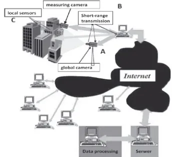
Civil engineering structures require monitoring of displacements and strains at different field of view (FOV) size and accuracy levels (Figure 1). In most cases three levels should be considered:
global – with FOV in the range of several tens or even hundreds of square meters and a few millimetres accuracy,
local – with FOV in the range of a few square metres and several micrometres accuracy, precise – with FOV in the range of a few millimetres and a nanometre accuracy.
Fig. 1. Scheme of complex monitoring system for civil engineering .
Data captured by different sensors is transferred via short-range transmission links to a local storage database, then via a WAN-type network to the central server, where data processing and analysis are performed. This kind of approach gives direct access to the database to all authorized personnel and Institutions via the Internet.
The characteristic of sensors used in the hierarchical monitoring system is presented below. Measurements performed within different accuracy levels ensure completeness of information about the health of a structure. The sensors can be relatively easy to reconfigure if a suspicion arises of damage emerging in another zone of the object. Below we describe sensors (working in 2D, 3D and 4D modes). The 2D mode refers to plane displacement measurements, the 3D mode enables in-plane and out-of-in-plane displacement measurements and the 4D mode signifies sequenced measurements in real-time (so tests of varying-in-time objects are possible).
2.1 Global sensor
DIC sensor is used for in-plane displacement measurements (2D) of singular object points (also in real-time). It is working in a big area of interest (more than 10m x 10m in most cases). The measurement accuracy depends strongly on the detector resolution and the dimensions of the area of interest. If a large CCD matrix is used, the required accuracy of 1mm can be easily achieved. Integration of the global sensor is not necessary, as a digital camera with a big CCD matrix and well tailored software can be treated as a sensor itself.
2.2 Local sensor
The local sensor is based on a standard DIC technique. The sensor is used for the determination of a 2D or 3D displacement maps in crucial zones of an object (i.e. principal structural elements and near-support areas). The full field technique is perfect for indicating cracks in such zones and its supremacy (in terms of small damage detection) over single point methods is evident. A camera integrated with an embedded computer will be set to observe a local field of view (up to 4m2) with an accuracy of several micrometres. The accuracy, however, depends strongly on the FOV size and CCD matrix resolution and thus accuracy of 0,1 pixels is considered as a rational trade-off. Connectors for extending the sensor with another camera to enable 3D or 4D measurements will be located on the casing. In order to facilitate the measurements and improve the efficiency of data analysis, some additional connections and extensions will be available for the user (e.g. light-intensity module, GPS module, meteorological station).
2.3 Precise sensor
The integrated grating interferometry sensor is dedicated to in-plane displacements measurements in a small field of view but with nanometre accuracy. Sensors of that kind could be placed in crucial zones of the measured object to determine local strains or monitor propagation of cracks [10]. The sensor captures interferograms with spatial carrier in order to take measurements with as high frequency as possible (at least 15Hz). In this paper we do not present measurements by this precise sensor.
Here we focus on two mutually complementing configurations of the DIC sensor for measurements of civil engineering structures. The results from the local sensor are complemented by global measurements. However the specific character of outdoor measurements for civil engineering structures, implies additional necessary improvements and adaptations of the DIC sensor concerning both hardware and software.
3 Modifications of DIC data analysis
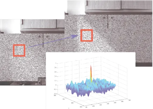
Fig. 2. The distribution of correlation between subsets of image taken under different lighting conditions (test object in lab).
To ensure that the data analysis takes as little time as possible (keeping in mind the large quantities of data that the complete system will generate), further improvements were necessary. The measured objects are expected to display relatively small displacements, and even more importantly, small deformations within the measurement field, which means that the algorithm does not need to account for large displacement gradients that would normally further impact the execution time. Therefore time can be also saved by searching for subsets near their original positions, with the search window circling outward along quasi-spiral paths. In addition, the algorithm avoids excessive calculations whenever possible, abandoning a search if the displacement cannot be identified after a pre-determined search radius has been exceeded, or if a probable match has been found and the correlation value keeps diminishing in subsequent iterations. Caching tables are utilized for storing and re-using partial values which are used to calculate the correlation coefficient. The duration of the analysis depends on the image size, parameter values and the capabilities of the utilized hardware, but it usually takes several seconds to process a 1024x768-sized image at default parameter values on a relatively up-to-date computer system.
Through a series of synthetic data and laboratory experiments, the accuracy of the implementation has been estimated to be close to 0,1px. However, the ability to determine subpixel displacements of less than 1px is somewhat limited, with the interpolation subsystem introducing errors manifested as oscillations in the post-processed distributions of calculateddisplacements.
4 Measurements of the railway bridge in Nieporet (Poland)
Fig. 3. a) View of the tested bridge with marked positions of b) global and c) local DIC sensors.
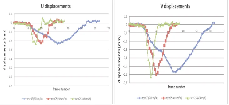
During the local sensor experiment a chartered locomotive (weight 120 tons) was passing through the bridge back and forth at 4 different speeds (20km/h, 40km/h, 60km/h, 80km/h). The local DIC sensor (Figure 3c) was placed on a concrete abutment so its stability, relative to the bridge, can be assumed. The local sensor was measuring displacements of the longitudinal truss girder (the left double-T beam in Fig. 3c) close to the riveted connection with the transverse double-T support beam. The joint of the abutment and the transverse support beam was assumed to be fixed in the FEM model (developed by IFTR). The local sensor (PointGrey Flea2 camera 1Mpx, 8mm lens) was capturing images with the FOV=0,7m x0,5m and the frequency of 7.5Hz, so each test contains 20 to 80 frames. The summarized results from three tests are presented jointly in Figure 4.
Fig. 4. „U”-horizontal and „V”-vertical displacements of the measured FOV.
support beam. Altogether, more than 30 tests were carried out. That amount of data helped to draw conclusions about the measured structure and prompted some directions of workson sensors.
During the global sensor experiment, loads were generated by a short passenger train (weight 35 tons). The global DIC sensor was observing deflections of the longitudinal truss girder in the middle of the bridge span. The view from the global sensor (Canon S7 digital camera with 150mm lens) is presented in Figure 5.
Fig. 5. The view from the global DIC sensor with marked analysis points.
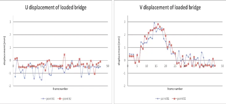
DIC analyzes were carried out for two points B1 and B2 (Figure 5). In order to increase the correlation ratio, cross markers were attached to the surface. Other markers were used to scale pixels to millimeters. The displacements of the B1 and B2 points (with the short train passing through) are presented in Figure 6.
Fig. 6. U and V displacements of points B1 and B2 (loaded bridge).
Fig. 7. U and V displacements of points B1 and B2 (unloaded bridge).
The amplitude of oscilations observed in Figure 7 can be treated as the uncertainty of the global measurements, however the amplitude is particularly big for small displacements (less than 1 mm). Taking into account the scale factor between the dimensions of the CCD matrix on the one hand and the area of interest on the other, the average measurement uncertainty equals +/-0,5pixels for displacements smaller than 1 pixel. The relatively higher error obtained for small displacements seems therefore to be caused by subpixel interpolation alghorithms, which do not perform very well for displacements smaller than 1 pixel.
The loads generated by the train and the locomotive are well described and modeled in the FEM, therefore the experimental results could be confronted with the FEM model of the bridge. Figure 8 illustrates the FEM model response in points B1 and B2 due to the trainpassing through.
Fig. 8. U and V displacements of points B1 and B2 calculated in FEM model
long-term wear of the about 50-year-old bridge. Discrepancies could also be caused by a quite substantial error of the subpixel interpolation algorithm.
5 Conclusions
The concept of a complex monitoring system of civil engineering structures and the concept of two non-contact sensors with different accuracy levels based on the DIC technique have been presented in the paper. The results of example measurements proved that mutually complementing DIC sensors could be useful in monitoring of civil engineering structures. The results obtained during in-situ tests of the bridge in Nieporet were compared with the corresponding FEM model matching each other satisfactorily. Future co-operation between the Division of Photonic Engineering (WUT) and the Smart-Tech Centre (IFTR) is supposed to bring about further development of the DIC-based method of measurements as a promising non-contact alternative to standard contact methods especially for civil engineering structures the access to which is limited or impossible.
6 Acknowledgements
The authors appreciate the assistance and contribution of Grzegorz Dymny, Krzysztof Malowany, Bartosz Siwek from the Division of Photonic Engineering. The financial support from the project “Health Monitoring and Lifetime Assessment of Structures” – MONIT – POIG.0101.02-00-013/08-00 from the EU Structural Funds in Poland is gratefully acknowledged.
References
1. J.M. KO, Y.Q., Technology development in structural health monitoring of large-scale bridges, Department of Civil and Structural Engineering, The Hong Kong Polytechnic University, Hung Ho, Kowloon, Hong Kong, Engineering Structures 27 (2005) 1715-1725 2. Y.H. Huang, L. Liu, F.C. Sham, Y.S. Chan, S.P. Ng, Optical strain gauge vs. traditional strain gauges for concrete elasticity modulus determination, Optik - International Journal for Light and Electron Optics, (August 2009)
3. Samir N. Shoukry, Mourad Y. Riad , Gergis W. William Assa, Longterm sensor-based monitoring of an LRFD designed steel girder bridge, Engineering Structures (2009)
4. R C Tennyson, A A Mufti, S Rizkalla, G Tadros, B Benmokrane, Structural health monitoring of innovative bridges in Canada with fiber optic sensors, Smart Mater. Struct. 10 (2001) 560-573
5. S. Chaki, G. Bourse, Guided ultrasonic waves for non-destructive monitoring of the stress levels in prestressed steelstrands, Ultrasonics, Volume 49, Issue 2, (February 2009) 162-171 6. M. Kujawinska, R. Sitnik, G. Dymny, M. Karaszewski, J. Michonski, J. Krzeslowski, K. Mularczyk, P. Bolewicki, Remote online monitoring and measuring system for civil engineering structures, Proc. SPIE, v. 7389, (2009) 738904-1-10
7. www.monit.pw.edu.pl
8. www.limess.com
9. www.dantecdynamics.com