228 |
P a g e
SIGNAL TO INTERFERENCE-NOISE RATIO BASED
FIXED STEP SIZE POWER CONTROL ALGORITHM
FOR WCDMA SYSTEM
Prachi
1, Parveen Singla
21
M.Tech Scholar ,
2Asst. Prof , Panipat Institute of Engineering and Technology,
Samalkha,Haryana, Kurukshetra University, (India)
ABSTRACT
Third-Generation based Wide Band Code Division Multiple Access (W-CDMA) systems have been designed for variable data rate services accessible to large number of users. But Co-channel, multichannel interference and noise is a major factor in constraining the performance of WCDMA systems. Power control is an essential function to remove these limiting factors and to enhance the network performance. In this paper power has been controlled by taking fixed step size instead of taking a range of power control step sizes. The power control step of 1.75 dB has been used to control the increment or decrement of the transmitted power based upon the received transmit power control command (i.e. TPC) at the mobile station from the base station. This has been done by taking applications of high data rate as per the requirement of network. The simulation result show that transmitted power (i.e. updated transmitted power) has been increased when the calculated SIR is less than target SIR and vice versa. It has also been shown that level of calculated user signal to interference ratio has been decreased as the data rate increases .The selection of target signal to interference value may increase the system capacity by completing the process faster.
Keywords: WCDMA Networks; Sirtarget, Sircalculated, Required Output Power
I.
INTRODUCTION
The third generation based WCDMA is the radio access method that provides low data rate voice to high data
rate multi-media services. WCDMA utilizes direct sequence spread spectrum (DSSS) technique that spreads the
baseband data by directly multiplying the baseband data pulses with a pseudo-noise sequence. The PN code can
be generated by using Barker codes, Walsh codes, Gold codes etc. [1]. The advantages of DSSS like soft
capacity, improved handoff mechanism, good signal quality and user security make it the best choice over other
multiple access schemes and also increases the WCDMA demand in mobile communication market [2]. But
multiple accesses, co-channel interference and various kinds of fading puts a limit on system performance and
the capacity of network [3]. Various kinds of techniques have been adopted in literature to improve the
229 |
P a g e
Power Control (PC) is the best alternative to enhance the performance of WCDMA system. Power control isneeded in both uplink and downlink direction in FDD as well as TDD systems for reducing the co-channel
interference. The detail of power control mechanism can be given in soft hand–over mode, ordinary and
compressed mode in order to improve the system performance [9]. Various power control algorithms have been
used to increase system performance. A new game algorithm for power control in cognitive radio in which,
considered power not only fulfill the system SINR requirements but also includes the effect of threshold power.
Adaptive power control algorithm for third generation based network that has dynamic range of transmitted
power step size [10-12]. Network capacity for high data rate applications is increased by considering smaller
value of target SIR.
The cellular CDMA networks control algorithms utilizes the concept of signal to noise ratio in calculating the
required output power for transmission at various data rate application. This is due to fact that each slot of
WCDMA frame contains 15 time slot with 10 ms duration of the frame. The downlink transmitted power has a
fixed value during a given time slot. Slots are updated according to the SIR comparison in WCDMA network.
Downlink power control uses the method of closed loop used to counter the uplink near far effect. The main
mechanism behind this is that it uses the calculated SIR in the same path.
In this paper we studied the proposed power control algorithm of WCDMA for high data rate applications by
calculating the user SIR based upon the received power of a user at the base station. TPC command is generated
in the form of 0 and 1 by the base station .Where 0 and 1 is define the decrease or increase the transmitted
power. Updated power value is transmitted by the mobile station based upon the received transmit power control
command (TPC) from the base station. Process is terminated at the base station if for updated transmitted power,
calculated SIR is nearly equal to the target SIR. The power control step of 1.75 dB has been used to control the
updated transmitted power. This step will either increase or decreases the updated transmitted power value. For
sending the request for decreasing updated transmitted power, transmitted power is divided with power control
step of 1.75 dB and for increasing updated transmitted power calculated SIR is multiplied by 1.75 dB. All these
work has been done for high data rate applications. So by this way updated transmitted power is controlled by
base station.
The organization of the remaining paper is as follows: In section II we have studied about the power control in
WCDMA system. In section III, basic system model is described used at the base station. In section IV,
proposed power control algorithm is presented. The detailed experimental results and discussions are given in
section V. Finally, we conclude the paper in section VI.
II.
POWER
CONTROL
IN
WCDMA
SYSTEM
Power control can reduce the interference in both global and CDMA mobile system. Power control is classified
into centralized and distributed power control. Centralized power control having the central controller. The
function of the controller is it collects all link gain information of the system. Then, power is controlled by
230 |
P a g e
practically unrealizable as the complexity of the equipment and bandwidth is wasted due to the extremesignaling between base stations. In distributed power control each base station measures the link gain and SIR to
control the power in that local link. Compared to centralized power control it is practically realizable as it does
not have complex signaling and its implementation is also easy.
Distributed power control divided into two parts. One is open loop power control and other is closed loop power
control. In open loop power control technique, user entity (UE) has the ability to set its output power to a
specific value that can be suitable for receiver. Output power is adjusted by evaluating the channel interference.
In this, received power level of the signal from the BS in the downlink is measured by the UE. If the user entity
receives less power from base station then it is obvious that there is large distance between UE and base station
and UE is required to increase the power. Such that adjusted power level is inversely proportional to the signal
level from the BS in the downlink. The open loop power control tolerance is ± 9 dB at normal conditions and ±
12 dB at extreme conditions.
Closed loop power control is based on SIR measurements at the cell receiver i.e. at the base station and output is
send from the B.S to the UE. Closed loop contain inner and outer loop power control. UE uses the command to
adjust the transmitting power for the BS; this is done by the inner loop having control frequency of 1500Hz. This method gives much better results that the open loop technique. One of the disadvantages of this power
control technique is that for any changes in the channel condition its response is slow. In uplink, When BS
receives the UE signal; it compares the signal strength with the pre-defined threshold value at the BS. Threshold
(target SIR) value is adjusted constant by the outer loop power control. If the UE transmission power exceeds
the threshold value, the BS sends a Transmission Power Command (TPC) to the UE to decrease its signal
power. If received signal is lower than the threshold target then BS sends a command to UE to increase its
transmission power.
The basic mechanism of algorithm used to set the updated transmitted power in closed loop power control
technique is given as
- if calculated SIR is greater than target SIR then base station will request to UE to decrease the transmitted
power;
- if calculated SIR is less than target SIR then base station will request to UE to increase the transmitted power.
III.
BASIC
SYSTEM
MODEL
Power control can be modeled with the help of user SIR and target SIR on the uplink WCDMA system. The
uplink case is explained and the SNR of Jth user is given by [13]
231 |
P a g e
interference of user J and is defined as the interference power coming from other links operating at the samefrequency band within the communication system affects the power control in WCDMA. Power control
mechanism take place at the base station and the signal transmitted by the UE which is received at the base
station is used for the SIR calculation. The uplink capacity of single cell would be maximized by minimizing the
required power [14].
IV.
PROPOSED
POWER
CONTROL
ALGORITHM
The proposed power control algorithm is based on received power level at the base station. Here the target SIR,
co-channel interference and noise level is set constant for the calculation of user SIR at the base station for the
uplink power control. Base station send the transmit power control command(i.e. TPC) to the user entity in
order to increased or decreases the transmitted power such that the calculated SIR of the received power at the
base station become nearly equal to the given target SIR. The step size of 1.75 dB is used to define whether the
updated transmitted power is increase or decrease for controlling the power.
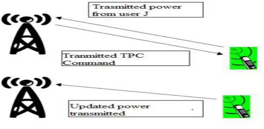
Figure 1. Uplink Updated Transmitted Power
In figure 1, describe the basic steps of proposed power control algorithm. User entity transmitting the power to
the base station that is calculated as user SIR by the base station and it is compared with the constant target SIR
of the base station. Base station sends the request to the user entity to increase or decrease the transmitted power
(i.e. updated transmitted power) for the better communication .In figure 2,3 and 4 procedure of above mentioned
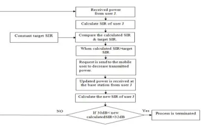
at 144kbps and 384kbps data rate is define in the form of flow chart. Process is terminated in case of 144 kbps if
new calculated SIR of the user after received updated power is in between 30 to 32 dB otherwise it is continue .
For 384kbps, process is terminated if new calculated SIR of the user after receiving updated power is in between
232 |
P a g e
In proposed power control algorithm at the base station, the transmitted power for the base station is set for theuplink direction as follow:
If the calculated SIR is greater than target SIR, request is send (i.e. TPC=0) to decrease the transmitting
power.
If the calculated SIR less than target SIR, request is send (i.e. TPC=1) to increase the transmitting
power.
In figure 4, flow chart of mobile user is explained as: TPC command is received at the mobile station. If
received command is 0 or1 then user is required to decrease or increase the transmitted power.
In proposed power control algorithm at the mobile station, the transmitted power for the base station is set for
the uplink direction as follow:
If mobile user received TPC=0, divide the received power of the user J by 1.75 dB.
If mobile user received TPC=1, multiply the received power of user J by 1.75 dB.
233 |
P a g e
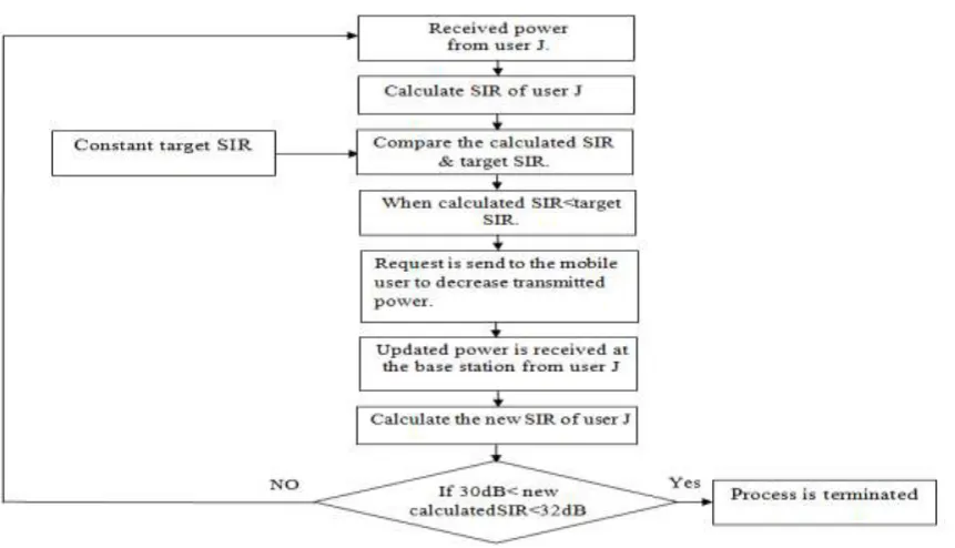
Figure 3.Flow Chart of Updated Transmitted Power when calculated SIR is less than target SIR
at the base station.
Figure 4.Flow Chart of Updated Transmitted Power at the mobile station.
V.
SIMULATION
AND
RESULTS
In this section, computer simulations have been conducted to validate the proposed method by observing the
graphs in between transmitted power of users and updated transmitted power of the users for better
communication and to increase system capacity. Here only one WCDMA cell with 1 BS (1 is considered.
The simulation on multi-user (i.e. 7) is performed where one user is controlled at a time and others acts as
interference. The number of mobile users (UE’s) in the simulated zone is 7 for 144kbps, 256kbps and 384kbps
data rate application. Here, various parameters such as chip rate (w) is taken as 3.84Mcps, voice activity factor
(v) is 1 has been taken for analysis. The co-channel interference is usually taken 0.6. In proposed algorithm a
constant target SIR at the base station is considered which is taken as 31 dB for 144kbps and 26 dB for 384kbps
234 |
P a g e
process.15 20 25 30 35 40 45 50 55 60 65 27 28 29 30 31 32 33 34
Transmitted Power of the users in dB
Ca lc ul at ed S IR o f t he U se rs in d B
Transmitted Power Verses Calculated SIR of the Users at 144 Kbps
Figure 5. Transmitted Power Verses Calculated SIR of the Users at Data rate 144 kbps.
15 20 25 30 35 40 45 50 55 60 65
0 10 20 30 40 50 60 70 80
Transmitted Power of the Users in dB
Up da ted T ran sm itte d P ow er of the U se rs in dB
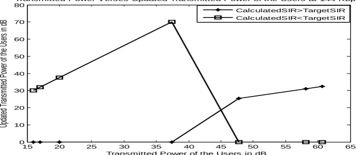
Transmitted Power Verses Updated Transmitted Power of the Users at 144 Kbps CalculatedSIR>TargetSIR CalculatedSIR<TargetSIR
Figure 6. Transmitted Power Verses Updated Transmitted Power of the Users at Data rate
144kbps.
User no. (J) Transmitted Power from the Jth user(Pj) (dB)
Calculat ed SIR of User J (dB) Updated Transmitt ed Power (dB) New calculated SIR Result(30dB<t arget SIR<32dB)
1. 16.02 27.28 30.04 30.00 Process is completed 2. 16.99 27.53 31.86 30.26 Process is completed 3. 20.00 28.24 37.50 30.96 Process is completed 4. 37.40 30.96 70.14 33.68 Process is continue 5. 47.78 32.02 25.48 29.29 Process is
continue 6. 58.20 32.88 31.03 30.14 Process is
completed 7. 60.71 33.06 32.37 30.33 Process is
completed
235 |
P a g e
In figure 5, graph has been plotted in between transmitted power verses calculated SIR of the users working atdata rate 144 kbps. Graph shows with increasing the transmitted power of the users there will be increase in the
value of calculated SIR of the user at the base station. In figure 6, it is observed that the updated transmitted
power increases if calculated SIR of the user is less than the target SIR of the base station and vice-versa as
define in table1. This is due to fact that as obvious that as the calculated SIR of user at the base station is less
than target, and then the user is required to increase its power and vice-versa.
15 20 25 30 35 40 45 50 55 60 65
23 24 25 26 27 28 29
Transmitted Power of the users in dB
Ca lc ul at ed S IR o f t he U se rs in d B
Transmitted Power Verses Calculated SIR of the Users at 384 Kbps
Figure 6.Transmitted Power Verses Calculated SIR of the User at Data rate 384kbps.
15 20 25 30 35 40 45 50 55 60 65
0 5 10 15 20 25 30 35 40
Transmitted Power of the Users in dB
Up da te d Tr an sm itt ed P ow er o f t he U se rs in d B
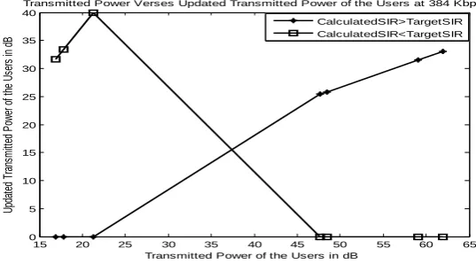
Transmitted Power Verses Updated Transmitted Power of the Users at 384 Kbps
CalculatedSIR>TargetSIR CalculatedSIR<TargetSIR
Figure 7. Transmitted Power Verses Calculated SIR of the User at Data rate 384kbps
.User no. (J)
Transmitted Power from the Jth user (Pj) (dB)
Calculat ed SIR of User J (dB) Updated Transmitt ed Power (dB) New calculated SIR Result(25dB< target SIR<27dB)
236 |
P a g e
6. 59.03 28.68 31.48 25.94 Process is completed 7. 61.97 28.89 33.04 26.16 Process is completed
Table2- Updated Transmitted Power Values w.r.t User no. for 26 dB target SIR.
In figure 6, graph has been plotted in between transmitted power verses calculated SIR of the users working at
data rate 384 kbps. Graph shows with increasing the transmitted power of the users there will be increase in the
value of calculated SIR of the user at the base station. In figure 7, it is observed that the updated transmitted
power is increases if calculated SIR of the user is less than the target SIR of the base station and vice-versa as
define in table2. This is due to fact that as obvious that as increasing the data rate, calculated SIR of the users
decrease and then it is significantly required to increased the amount of transmitted power of the user and
vice-versa under the condition of smaller target SIR at high data rate to accommodate large number of users. This is
due to fact that as obvious that network capacity is increased if target SIR is lowest for high data rate
applications.
VI.CONCLUSION
We studied the power control in 3G WCDMA based on received power from the mobile users. We notice that
the proposed power control algorithm is easily implemented at fixed power control step. We show some result
of the proposed power control algorithm at high data rate. The important parameters of proposed power control
algorithm is target SIR. The fastest termination of the proposed power control algorithm may give a capacity
increase and prevent from wastage from resources.
REFERENCES
[1]Y.P. Chang, W-CDMA for UMTS Taipei, Scholars Books, 2005.
[2]T.S.Rappaport. Wireless Communications: Principles and Practice, Prentice Hall, New Jersey, 2004.
[3]B. Smida, V. Sampath and P. Marinier, “Capacity degradation due to coexistence between second
generation and 3G/WCDMA systems,” in Proc. IEEE 55th Veh. Technol. Conf., Canada, vol. 1, pp.
95-99,May 2002.
[4]P.Singla and J.Saxena, “Enhanced capacity analysis in WCDMA system,” Int. J. Elect. Commun. Eng., vol.
4, no.1, pp.69-82, March 2011.
[5]A.G.Flattie, “Capacity improvement for WCDMA network,” in 6th Joint IFIP Wireless Mobile Networking
Conf., Dubai ,UAE, pp. 1-7,April 23-25, 2013.
[6]B.Hagerman, F.Gunnarsson, H. Murai, M. Tadenuma, and J. Karlsson, “WCDMA uplink parallel
interference cancellation - system simulations and prototype field trials,” EURASIP J. Applied Signal
Processing, vol.11, pp.1725-1735, July 2005.
[7]P.Singla and J.Saxena, “Modified optimum beamforming for smart antenna in WCDMA system,” In Proc.
IEEE Int. Conf. Machine Intelligence Research Advancement, IEEE Computer Society, Katra, Jammu,
237 |
P a g e
[8]H.Liu, F.Gu, Y.Cheung and S.Xie, “On solving WCDMA network planning using iterative power controlscheme and evolutionary Multiobjective algorithm,” IEEE Computational Intelligence Mag., vol. 9, no.1,
pp. 44-52, Feb. 2014.
[9]M.M. Rahman, K. Islam, T. Hassan-Al-Mahmud, A. R. Mahmud, “ Performance Analysis of Downlink
Power Control In WCDMA System ,” International Journal of Scientific & Engineering Research Volume
3, Issue 8, August-2012.
[10]L. Nuaymi, X. Lagrange and P.Godlewski, “A power control algorithm for 3G WCDMA system", in Proc.
of the European Wireless conference, 2002.
[11]R. Patachaianand and K. Sandrasegaran, “Performance Comparison of Adaptive Power Control in UMTS”,
in Proc. 2nd International Conference on Wireless Broadband and Ultra Wideband Communications, IEEE
2007.
[12]S. Naghian, M. Rintamaki and R. Baghaie, “Dynamic step-size power control in UMTS", in Proc. 13th IEEE
International Symposium on Personal, Indoor and Mobile Radio Communications, vol. 4, pp. 1606-1610,
2002.
[13]H. Lin, R. Juang, D. Lin, Cheng and Y.Wang,” A Cell Planning Scheme for WCDMA Systems Using
Genetic Algorithm and Measured Background Noise Floor”, in IEE Proceedings Communications; 151;
595-600.
[14]A.G.Flattie, “Capacity improvement for WCDMA network,” in 6th Joint IFIP Wireless Mobile Networking
Conf., Dubai, UAE, pp. 1-7, April 23-25, 2013
EXAMPLE FOLLOWS
BOOKS
[1] T.S.Rappaport. Wireless Communications: Principles and Practice, Prentice Hall, New Jersey, 2004.
GUIDED BY