215 | P a g e
STUDY ON IMPLEMENTATION OF CLASH
DETECTION TOOL IN HOUSING PROJECT USING
BIM
Abubakkar Sidiq A
1, Dr.P.Thamilselvi
21
M.E Student, Department of Civil Engineering, College of Engineering,
Anna University, Chennai (India)
2
Associate Professor, Dept. of Civil Engineering, College of Engineering,
Anna University, Chennai (India)
ABSTRACT
:
Building Information Modelling(BIM) has been recently emerged as a highly efficient solution for information managementin Architecture, Engineering and Construction (AEC) industry. In Indian construction scenario most of the projects are still using 2D CAD drawing for their execution purpose. These 2D drawings have lot of problems duringexecution like miscommunication,misunderstanding and time consuming, etc., This types of errors will be reduced while using BIM process. Clash detection tool is an application of BIM which is used for the coordination of building systems within 3D building models. This papergives a brief introduction about Clash detection in BIM and it focus the methodology involved conducting clash detection analysisusing buildinginformation modeling software. This workalso involves finding out, how this clash detection tool helps to optimize the cost and time for the construction of apartment building using BIM Coordination. As such, it is study of a G+3 apartment building which consisting of an architectural, structural and Mechanical, Electrical and Plumbing (MEP) BIM models and their consequent clash detection. Benefits and drawbacks of 4D BIM model were discussed. And Quantity analysis for some materials has been carried out. In this study, commercial software such as Autodesk Revit 2017, Autodesk NavisworksManage 2017 are used. It also focuses on the process of simplifying and standardizing the process of Clash Detection using Autodesk Navisworks. The study reports that the savings of material is obtained. The total cost of the project will not be increased and completion of the project on time avoids overruns.
Keywords: AEC Industry, Building Information Modeling, BIM Software’s, Clash Detection, Quantity
Analysis.
I.INTRODUCTION
Building Information Modeling (BIM) is process that supports virtual design and construction methodologies
putting all team members together throughout the entire design and construction process and beyond to the
216 | P a g e
real-time, intellectual modelling software effectively workingin 3D, 4D (3D + time), and 5D (4D +cost),6D(5D+ facilities management)to improve productivity, to save money and time in the design and
construction phases, and to reduce operating costs afterconstruction. Clash detection is one of the tool helps
to optimize the time and cost of the construction.
The National Building Information Modeling Standards (NBIMS) committee of US defines BIM as, “a
digital representation of physical and functional characteristics of facility. BIM is a shared knowledge
resource for information about a facility forming is liable basis for decisions during its life cycle i.e. from
earliest conception to demolition. A basic premise of BIM is the collaboration by different stakeholders at
different phases of the life cycle of a facility to insert extract, update or modify information in BIM to
support and reflect the roles of that stakeholder”.
II. CLASH DETECTION
Clash detection remains the primary requirement of any multidisciplinary project wherein composite design
needs to be inspected for the identification of clashes. Clash Detection is the method of inspecting and
identifying the various interferences which frequently occurs in coordinating process of 3D models created
in different modern software‟s like Revit Architectural, Revit Structural & Revit MEP .In BIM, 3D models
for different types such like Structural, Civil, and Architectural &MEP(Mechanical, Electrical and
Plumbing). When combination of all these different types of models to create a complete BIM model there
will be chances of clash between these elements.
In clash detection test it detects the conflicts between different elements within 3D Building Information
Model before actually construction starts, and therefore time optimization in the construction schedule,
reduce costs and change orders. By using clash detection application in AEC industry increase the
productivity of design and construction project.
2.1 Need of Clash Detection
In traditional method organizations prepares activities for the execution stage as establishing contracts with
contractors, buying materials, ensuring a good coordination and assembly order of the different systems of a
project. The most clashes are recognized when the contractor receives the design drawings and everyone is
on-site and working. It is compare with 2D designs to each other to find conflict clashes between the
specialty designs. Because the specialty contributors i.e. structural engineers, MEP engineers etc. develop
their designs separately, so when comparing these designs on different drawings is a process easily overlook
clashes. The contractors require seeing that the detailing of structural elements, plumbing, electrical lines
and other component is done well. If there is some mistake in of these clashes result change orders then
these effects on cause delay in project, design modifications, materials costs and budget overruns. Using
BIM and the Clash Detection application enables potential problems to be identified early in the design
217 | P a g e
III. INFERENCE
Based on literature review,the past application of BIM is to design and development of 3D BIM model
required for construction scheduling which lead to a creation of 4D model. And also its benefits, obstacles,
problems, developments are to befounded. Day by day, Indian construction industries are moving towards
theBIM process to increase their profits and also to complete the projectwithin budget & time. BIM tools are
introducing new technologies for optimizing the construction process. In this project, one of the optimistic
tool of Clash detection had been evaluated in the apartmentbuildings. Quantity analysis conducted for
apartment. Also benefits and drawbacks of 4D BIM were discussed.
3.1 Scope of Work
In this project, 3D model of the apartment‟s architecture had been created by Revit Architecture software.
Structural details of this building had been created by Revit Structure software and MEP (Mechanical,
Electrical and Plumbing) services had been created by Revit MEP software. And the scheduling had beendone
by Microsoft Project (MSP). The Architectural, structural and services models were imported into
Navisworks software to identify the clashes among various disciplines. The clashes were identified,
resolved and the 3D BIM model was updated to incorporate these resolved clashes. And finally quantity
analysis carried out for this model before and after clash detection.
IV. METHODOLOGY
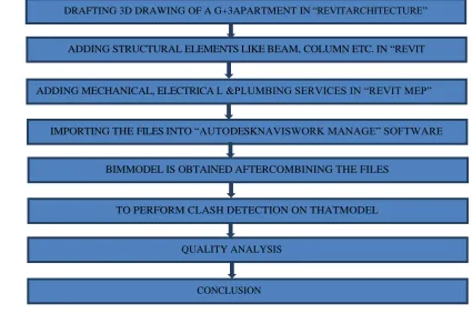
The following flowchart explains the sequences of creating the 4D model.
Fig. 1Methodology
DRAFTING 3D DRAWING OF A G+3APARTMENT IN “REVITARCHITECTURE”
ADDING STRUCTURAL ELEMENTS LIKE BEAM, COLUMN ETC. IN “REVIT STRUCTURE”
ADDING MECHANICAL, ELECTRICA L &PLUMBING SERVICES IN “REVIT MEP”
IMPORTING THE FILES INTO “AUTODESKNAVISWORK MANAGE” SOFTWARE
BIMMODEL IS OBTAINED AFTERCOMBINING THE FILES
TO PERFORM CLASH DETECTION ON THATMODEL
QUALITY ANALYSIS
218 | P a g e
V. MODEL CREATION
5.1 Data Collection
The plan of a G+3 residential apartment, which is a proposed project in Coimbatore, Tamilnadu by SLN
Builders is taken for study. CAD file of extension “.dwg” is obtained which contains floor plans. The area
of this G+3 apartment is around 3110 ft2 and total construction area is about 12443 ft2.
Fig. 2 AutoCAD Screenshot
5.2 Autodesk Revit
There are lot of software‟s available for creating 3D model, but Autodesk Revit which is the
best software in this area is used here.
In this project Revit software 2017 version is used for creating the 3D file.
In Autodesk Revit, Revit Architecture, Revit Structure and Revit MEP (Mechanical, Electrical
& Plumbing Design) are to be created separately and finally it is to be coordinated with each
other.
Each discipline have separate template file for making model.
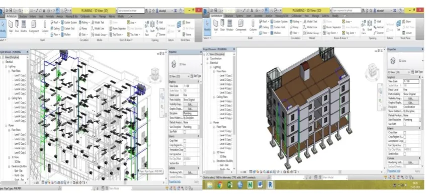
Revit architecture rendering image are represented in figure 3. Revit Structure 3D view is
shown in figure 4. And Revit MEP 3D view and Coordination image are shown in figure 5&6.
219 | P a g e
Fig. 5 Revit MEP 3D View Fig. 6 Revit Co-ordination (Architecture, Structure, MEP)VI. PROCESS OF CLASH DETECTION
The procedure involved collecting three model files of type “.rvt” (Autodesk Revit 2017) for the three models,
i.e. architectural and structural and MEP model. Three separate clash tests were conducted:
1) Architectural Model versus Structural Model (AR Vs ST),
2) Architectural Model versus MEP Model, (AR Vs MEP)
3) Structural Model versus MEP (ST Vs MEP).
The software was set to detect only hard clashes, with a tolerance of 0.001 mm. There is much BIM software
available in market which is useful for design and construction professionals to increase the productivity of the
project, but in this study software used for clash detection process is Autodesk Navisworks Manage 2017.
Autodesk Navisworks Manage greatest strength is clash detection. Due to this software detecting collisions
during design, in real time, gives the BIM stakeholder a very efficient method to improve coordination among
multiple building systems and ultimately avoid costly remedies after drawing completion and during
Construction phase. Following are the steps for clash detection process.
The first step in this study is to import all the Revit 2017 files i.e. MEP, structural and architectural
files into Navisworks which is used in clash detection process .For clash detection process in
Navisworks, it is required to import 3D Revit files into Navisworks or export files from Revit to
Navisworks.
220 | P a g e
Fig. 7 Converting Revit file into „.nwc‟ format Once all Revit files are transformed into „.nwf‟ file format, files are opened in Navisworks software
and then clash tests are carried out by using rvt files.
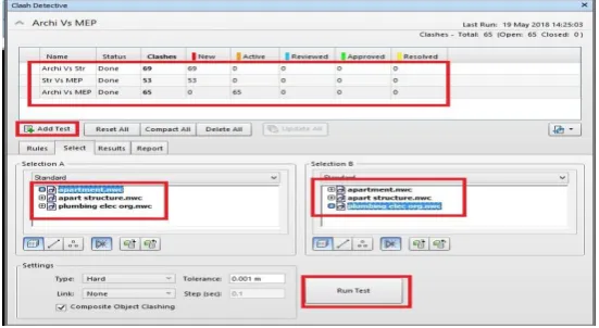
Clash tests in Navisworks software is performed by pressing the „Clash Detective‟ tool.
„Select‟ tab is made click on that is located within clash detective tool in Navisworks software.
Then two different columns will appear on computer screen so select different model elements which
have the chances of conflicting with each other which is shown in figure 8. For example structural
element can interfere with MEP element, so in one column we should select „structural element‟ and in other column we should chose „MEP element‟ and then made click on „OK‟ to run clash test.
Fig. 8 Clash Detection Process by Naviswork
After the clashes between structural element and MEP element are being easily recognized. Result
inspection is done using Results tab.
Autodesk Navisworks automatically gives a status to each clash for future use .The Clash Detective
tool that keeps on updating the status of the clashes after they are identified and are listed within
221 | P a g e
Fig. 9 Clash Detective showing the results tab Further, for creating report of clash test Report tab is made click on and report created in „.HTML‟ file
format which is shown in fig 10& 11.
Fig. 10 Clash Detective showing the report tabFig. 11 Clash report generated by Navisworks
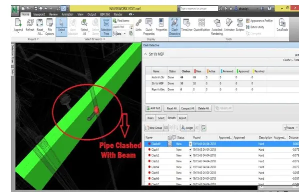
Clashes can be resolved using clash report element ID by changing position of particular element i.e.
figures 12, 13&14 shows the clash can be resolved by changing the length of pipe.
222 | P a g e
Fig.13 Pipe position before clash resolvingFig. 14 Resolving clash between pipe & beam by changing length ofpipe
In our project totally around 182 clashes are detected in clash test. And all the clashes are resolved
using element ID exported in clash report. The clash we assigned is visible in Autodesk Revit, once we open it
and paste the element ID in „Select by ID‟ tab in Revit. Each clash can be selected to know the location of it and
separate labeling can be done too. From Revit Architecture the rectified file is exported in „.nwf‟ format. Once
the changes are done the file Navisworks is opened again to check for clashes. The clash report can be exported
as text file or HTML file.
VII. RESULTS & DISCUSSIONS
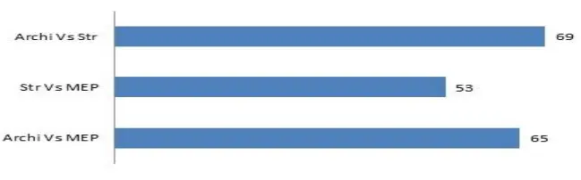
In this study while conducting clash detection test, three various disciplines were compared with each other.
The final result of clash test reports for Architecture Versus Structure are 69 clashes, Structure Versus MEP
are 53 clashes and Architecture Versus MEP are 65 clashes. Each clash was separated by category and
resolved using element ID of that clashing members. The element ID was copied from the clash report and
that ID pasted into the Revit to locate the clashing elements. Finally it is resolved by changing the element.
Fig. 15 Clash Test Report
Before conducting clash test the quantity of whole building was taken from Autodesk Naviswork. The
223 | P a g e
clashes, again quantities are taken from Autodesk Naviswork and exported in excel format. Both quantities arecompared. After resolving all clashes some construction materials quantities are found to have slightly
change.The concrete quantity before clash test is 288.76 m3 and after clash test completed, it was decreased as
285.1 m3. Nearly 3 m3 volume of concrete was saved. And the Bricks quantity is also decreased nearly 4 m3 by
volume. The cement mortar decreased nearly 1 m3 by volume. But the steel quantity didn‟t change because the rebars are embedded into the structural elements, so it didn‟t clash into another element. Nearly 1% of each
material was saved in design stage while using clash detection. This 4D BIM model save more percentage of
cost and time during construction progress. The quantity analysis is one of the benefits of 4D BIM. The other
benefits are discussed below.
Fig. 16 Quantity Analysis
7.1 Advantages
BIM is one of the biggest boons for Construction Manager‟s, because it simplifies most of the management
activities. Architects, contractors and engineers refer the 4D BIM model for various reasons and implement
the information received from it for construction purposes.
BIM modeling visualization incorporates start and finish date data for the supply and installation of
construction components and reveals the importance of them in relation to the overall project. It
has removed the challenge associated with traditional scheduling of construction sequences of
misunderstanding brought about by the lack of visualization.
With clash detection, mistakes which normally would have been discovered on the site (with high cost
and schedule implications when corrected at that stage) can now be seen in the office even before
anyone sets foot on the site.
Reduce the risk of human errors during model inspection.
Improve Procurement – BIM model helps to procure the materials in perfect time and perfect quantity
(i.e., even the pipe fitting accessories like elbow, couplings count). So the wastage of materials will
decrease.
Improve Productivity – Using BIM model decides the period of the equipment need for the site work.
224 | P a g e
Improve Quality – The accuracy of building improved and also quality wise also improved.
BIM allows seeing potential problem areas and fixing them before the error is committed in the
physical world. This reduces the need for costly rework and revision.
Using BIM 360 Mobile Application, all files can be accessed in site itself.
Fig.17 BIM 360 Mobile Application
BIM model can be referred throughout the life-cycle of a project.
With the assistance of a BIMmodel designers and engineers can improve the design constructability.
The benefits of different construction processes can also be determined by 4D models during the design
development phase. The project teams can optimize the construction schedules with the help of the
model. It can also be used by the contractors for showing the phasing plans to the owners etc.
7.2 Drawbacks
Cost of software: BIM software requires a substantial investment in new technology. The advantages
usually make the investment worthwhile, but only if the software is used to its full capacity.
Lack of experts: The relative newness of BIM means that there are limited numbers of experts
working in the field. So software purchase may require an additional investment in training and
education.
Incompatibility with partners: BIM is not yet universally used among construction professionals.
There is always the possibility that one of your partners or subcontractors may not use BIM and may
not be able to use your models.
Consume Time: BIM consumes more time in design phase. So it is not preferable for small and
medium level of construction projects.
Building Information Modelling have more merits, measure its whole percentage of savings in design phase is
impossible. The only way is to compare two buildings with BIM and without BIM. It takes more time to
225 | P a g e
VIII. CONCLUSION
Building Information Modeling (BIM) is rapidly growing within the Architecture, Engineering
&Construction (AEC) industry where its current implementation shows great effects on projects in
terms of performance, time and cost.
Indian construction industry is not very familiar in applying the true potential of BIM tools and its
capacity.
Using Clash detection in this study instead of traditional method detects the conflicts in 3D Model
before starting of actual construction so that it is useful to decrease coordination errors, human errors
which results in high level of accuracy of models. Hence re-work in jobsite can be avoided.
In this study totally 182 clashes are identified and they are resolved. So in the result of G+3 apartment
building nearly 1% saving of materials is observed in quantity analysis. In this saving is design phase
only, when in this model implement in real time construction, it helps to save more time & cost.
Autodesk Navisworks makes the clash detection process faster and easier along with completely reducing the scope of human errors during its execution. Design clashes that occur between buildingelements are successfully identified by Navisworks and they are timely solved. Hence complete
elimination of design errors, optimize time and cost is very important for AEC industry before actual
construction starts on jobsite.
Hence, implementation of clash detection tool is very important for error-free construction project which helps to optimize time in the construction schedule and minimize the overall cost of project atthe construction stage.
REFERENCES
[1] National Building InformationModelingStandard(NBIMS),Overview,Principles
andMethodologies,Version1.0 - Part1, http://www.wbdg.org/building-information-modeling-bim.
[2] PranavBhagwat,RahulShinde(2016),‘ClashDetection-A NewToolinProject management’,International Journal of Scientific Research in Science, Engineering and Technology ( IJSRSET), Volume 2,Issue4,pp:592-599.
[3] Swapnesh P Raut, S SValunjkar (2017), ‘Improve the Productivity of Building Construction Project using
Clash detection Application in Building Information Modeling’, International Research Journal of Engineering & Technology ( IRJET),Volume-4, Issue-3, pp: 1784-1790.
[4] Salman Azhar(2012),‘Building Information Modeling (BIM): Trends,Benefits, Risks, and Challenges for
the AEC Industry’, Leadership and Management in Engineering, pp:241-252.
[5] BhamreGauravShyamkant, AshwiniPatil, SmitaPataskar (2017), „Cost and Time Optimization for Construction of Residential Building by Clash detection in Building Information Model(BIM)‟, International Research Journal of