ISSN: 2319-8753
I
nternational
J
ournal of
I
nnovative
R
esearch in
S
cience,
E
ngineering and
T
echnology
(An ISO 3297: 2007 Certified Organization)
Vol. 2, Issue 10, October 2013
Fabrication and Electrical Characterization of
PEM Fuel Cell based on (PEO+KHCO
3
)
Polymer Electrolyte Membrane
Dr. K. Vijaya Kumar, Dr. G. Sunita Sundari & N. Krishna Jyothi
Dept. Of Physics, K L University, Guntur-522 502(A.P)-INDIA
Abstract: An attempt has been made in the present work to develop a new Polyethylene oxide (PEO) based Solid polymer electrolyte membrane, (PEO+KHCO3) by Isothermal immersion- technique. Several experimental techniques
such as IR, composition dependence conductivity, temperature dependence conductivity in the temperature range of 308- 368K and transport number measurements were employed to characterize this polymer electrolyte membrane system. The IR studies confirm the salvation of K+ ion with PEO. The conductivity of the (PEO+KHCO3) electrolyte
was found to be about 3 times larger than that of pure PEO at room temperature. The transference data indicated that the charge transport in these polymer electrolyte systems is predominantly due to ions. Using this conducting polymer electrolyte membrane, a polymer electrolyte membrane (PEM) Fuel cell stack was fabricated with the configuration anode/polymer electrolyte/cathode and studied its I-V Characteristics. The results of these investigations are reported in this present paper.
Keywords: Isothermal immersion, polymer electrolyte, ionic conductivity, transport number, Polymer Electrolyte Membrane(PEM)fuelcell,current(I)-voltage(V)Characteristics.
I. INTRODUCTION
The two primary concerns of scientists today are energy and environmental with the rapid depletion of fossil fuels.
There is an urgent need to look for clean alternate source of energy. Fuel cells satisfy both these criteria. It’s high time
that we realize the need for cutting edge technologies which satisfy both the conditions i.e. being able to match the
present day demand and also being reliable. One such convincing technology is “Fuel cell technology”. The necessity
for this technology has been widely accepted globally in the energy and power sectors. Of the many emerging technologies such as Biomass Fuels, liquid-bio fuels, geothermal energy, Photo-voltaic, Hydro-electric power, solar thermal-electricity, tidal-energy, wind-energy, fuel cell technology has been much considered comparative with other technologies and if developed, has more advantages because it has the practicability of being used in many mobile applications and hence this seems to be the futuristic technology [1-2].
On the world wide automobile market technical developments are increasingly determined by the dramatic restriction on emissions and increasing pollution levels. Therefore there is a necessity for a completely new technology to break through if it offers an answer by its principle, meeting the requirements of resource preservation and emission restrictions. The fuel cell technology has the potential, in terms of environmental compatibility and efficiency [3] .Fuel cells are an important technology for a potentially wide variety and range of applications including transportation power for automobiles, stationary and distributed power for rural areas, portable power for laptops, mobile phones etc. it will be decided by the costs of fuel cell systems if they will be used as power generators in future. Presently the objective is to lower the costs for all types of fuel cells by mass production.
ISSN: 2319-8753
I
nternational
J
ournal of
I
nnovative
R
esearch in
S
cience,
E
ngineering and
T
echnology
(An ISO 3297: 2007 Certified Organization)
Vol. 2, Issue 10, October 2013
developments and fundamental issues related to these solid electrolytes have been reported in reviews by many researchers [6, 7].
In general, the polymer component of PEO based composite electrolyte is a mixture of crystalline and amorphous phases, ratio of which depends to a great extent on compositions of the electrolyte, temperature and thermal history. The solid polymer electrolytes i.e. polymer salt complexes are of technological interest due to their possible application as solid electrolytes in different devices such as energy conversion units (batteries/fuel cells), electro chromic display devices/smart windows and photo-electrochemical solar cells etc [8-11] Subsequently studies on PEO-based polymer electrolyte complexes using alkali salts [11-13] were developed in this field.
In the present paper, the authors report solid ion conducting polymer electrolyte based on (PEO+KHCO3) membrane
system. Several analytical techniques, such as IR, composition dependent conductivity, transport number measurements and temperature dependent conductivity in the temperature range 308-368K were performed to characterize these polymer electrolytes. Based on these solid conducting electrolytes, a PEM Fuel cell stack was fabricated with the configuration anode/polymer electrolyte/cathode and studied its I-V Characteristics. The results of these investigations are reported in this present paper.
II. EXPERIMENTAL
Pure PEO (Aldrich 6x10⁵) complexed with a fine powder of potassium bicarbonate salts (KHCO3) were prepared in
the stoichiometric ratios (90:10), (80:20), (70:30) by an Isothermal immersion- technique using methanol (water free) as solvent. The IR spectra in these films were recorded with the help of JASCO FT/IR-5300 spectrophotometer in the range 400-4000cm-1.
The dc conductivity has been measured using the lab made conductivity set up [13] in the temperature range 303-368K. The ionic and electronic transport numbers (tion and tele) were evaluated by means of Wagner’s polarization technique
[14, 15]. In this technique, a freshly prepared film of PEO+KHCO3 under a dc bias (step potential 1.5V) was used. The
resulting current was monitored as a function of time with a keithley electrometer (Keithley Inc., model 614).
Finally a PEM fuel cell was fabricated with the configuration anode/polymer electrolyte/cathode and studied its I-V Characteristics. The details about the fabrication of Polymer electrolyte fuel cells are given elsewhere [16, 17]. The current-voltage characteristic studies of these PEM fuel cells stack were monitored at a constant load of 0.5.
III.RESULTSANDDISCUSSION
The variation in dc conductivity () as a function of KHCO3 composition in PEO from room temperature (RT) to 368K
is given in Fig 1. Conductivity data at RT and 368K are reported in Table 1. The following conclusions can be drawn.
(a) The conductivity of pure PEO is approximately 10-10 Scm-1 at room temperature and its value increases sharply to 10-7 Scm-1 on complexing with 10 wt % KHCO3. The increase in conductivity becomes slower on further addition of
KHCO3 to the polymer. This behavior has been explained by various researchers, who have studied PVP and PEO
based polymer electrolyte in terms of ion association and the formation of charge multipliers [18-21, 23]
(b) The ionic conductivity in the polymer complexes may be interpreted on the basis of a hoping mechanism between coordinating sites, local structural relaxations and segmented motions of the polymer chains. These are essential to assure high conductivity of the electrolyte[22-24].
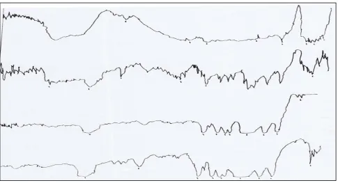
The complexed polymer PEO and salt KHCO3 were confirmed by using IR spectroscopy. The IR spectra of pure PEO,
PEO complexed with KHCO3 were recorded with the help of JASCO FT/IR–5300 spectrophotometer in the range
400-4000 cm-1 and are shown in Fig-2. The intensity of the aliphatic C-H stretching vibrations band observed around 2950cm-1 in PEO was found to decrease with the increase in the concentration of KHCO3 salt in the polymer. The
ISSN: 2319-8753
I
nternational
J
ournal of
I
nnovative
R
esearch in
S
cience,
E
ngineering and
T
echnology
(An ISO 3297: 2007 Certified Organization)
Vol. 2, Issue 10, October 2013
the IR-spectra directly indicates the complexation of PEO with KHCO3. This IR data clearly establishes the
complexation of KHCO3 with different weight ratios of the polymer PEO.
Fig. 1: Composition dependence of (PEO+KHCO3) polymer electrolyte system at different temperatures
Fig-2 IR Spectra of
a) Pure of PEO b) PEO + KHCO3 (80:20)
c) PEO + KHCO3 (70:30) d) KHCO3
-10 -9 -8 -7 -6 -5 -4
0 5 10 15 20 25 30 35
Composition
ISSN: 2319-8753
I
nternational
J
ournal of
I
nnovative
R
esearch in
S
cience,
E
ngineering and
T
echnology
(An ISO 3297: 2007 Certified Organization)
Vol. 2, Issue 10, October 2013
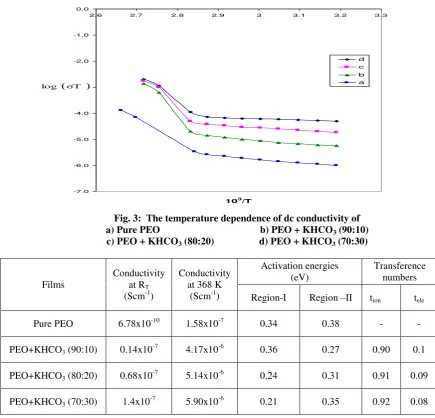
The variation in conductivity as a function of temperature for pure PEO with different compositions of (PEO + KHCO3)
polymer electrolytes over the temperature range of 303-368 K is shown in Fig-3. The conductivity increases with temperature in pure PEO and also in all the compositions of polymer electrolyte systems. The conductivity versus temperature (log T versus 103/T) plots follows the Arrhenius nature throughout, but with two different activation energies above and below melting point (Tm) of the polymer. In region- I (i.e., below Tm) the conductivity of pure PEO
increases slowly with temperature up to 65oC. At 65oC there is a sudden increase in conductivity. In region- II (i.e., above Tm), the conductivity again increases with temperature. The calculated conductivity () at room temperature, at 368K and activation energies (Ea) for pure PEO and (PEO+KHCO3) electrolyte systems are given in Table 1. The
conductivity of pure PEO is 6.7810-10 Scm-1 on complexing with 10 wt % KHCO3. Further addition of KHCO3 to
the polymer, the increase in conductivity becomes slow. This behavior has been explained by various researchers, who have studied PEO and PEO based electrolytes, in terms of ion association and the formation of charge multipliers [25-29, 32].
Fig. 3: The temperature dependence of dc conductivity of a) Pure PEO b) PEO + KHCO3 (90:10)
c) PEO + KHCO3 (80:20) d) PEO + KHCO3 (70:30)
Films
Conductivity at RT
(Scm-1)
Conductivity at 368 K
(Scm-1)
Activation energies (eV)
Transference numbers
Region-I Region –II tion tele
Pure PEO 6.78x10⁻¹⁰ 1.58x10⁻⁷ 0.34 0.38 - -
PEO+KHCO3 (90:10) 0.14x10⁻⁷ 4.17x10⁻⁶ 0.36 0.27 0.90 0.1
PEO+KHCO3 (80:20) 0.68x10⁻⁷ 5.14x10⁻⁶ 0.24 0.31 0.91 0.09
PEO+KHCO3 (70:30) 1.4x10⁻⁷ 5.90x10⁻⁶ 0.21 0.35 0.92 0.08
Table 1: Conductivity, Activation energies and Transference numbers of PEO+KHCO3) electrolyte system -7.0
-6.0 -5.0 -4.0 -3.0 -2.0 -1.0 0.0
2.6 2.7 2.8 2.9 3 3.1 3.2 3.3
103 /T
d c b a
(σT )
ISSN: 2319-8753
I
nternational
J
ournal of
I
nnovative
R
esearch in
S
cience,
E
ngineering and
T
echnology
(An ISO 3297: 2007 Certified Organization)
Vol. 2, Issue 10, October 2013
Total ionic transference number of polymer electrolyte has been measured by Wagner’s Polarization technique [14, 18],
which is used to determine the ionic contribution to the total charge transport by measuring the residual electronic current passing through the electrolytes. Three Wagner polarization cells Ag/ electrolyte/Ag were prepared by coating silver (Ag) paste as blocking electrode on to the faces of PEO+KHCO3 based composition polymer electrolyte systems.
A fixed small dc potential (1.5V) has been applied across the blocking electrodes and the current passing through the cells is measured as a function of time for one hour to allow the samples to become fully polarized are shown in Fig.4.
Fig.4: Current versus Time plot of a) PEO+KHCO3 (90:10)
b) PEO+KHCO3 (80:20) c) PEO+KHCO3 (70:30)
Initial total current (IT) which is the sum of ionic (Ii) and electronic (Ie) currents (IT= Ii + Ie) and final current after
polarization which is only the electronic current (Ie) are measured. The ionic transference number ( tI ) is calculated
using the relation
tI = Ii / IT = (IT - Ie) / IT
The ionic transference number for all the compositions of the (PEO + KHCO3) electrolyte system were shown in Table
1. The values of the ionic transference numbers (tI) are in the range 0.90 – 0.92 suggest that the charge transport in these
polymer electrolyte systems is predominantly ionic accompanied by mass transport and electronic contribution to the total current is negligible.
The basic design of the cell, which consists of a solid electrolyte ion-exchange membrane, electro catalysts and gas feed fuels is illustrated in Fig.5.The distinctive feature of this cell is that it uses a solid polymer electrolyte in the form of an ion-exchange membrane. The membrane is non-permeable to the reactant gases, hydrogen and oxygen, which thus prevents them from coming into contact. The membrane is however; permeable to hydrogen ions [33] which are the current carriers in the electrolyte .The desired properties of polymer electrolyte membrane are high ionic conductivity, low permeability of fuel and oxidant, Very low electronic conductivity, high resistance to its oxidation or hydrolysis and Mechanical stability [34].
The two electrodes, which consist of the electro catalyst and a plastic material for water-proofing the electrode, are in the form of fine metallic wire screens. They are bonded on either side of the electrolyte layer. The wire screen material is titanium or platinum. Metallic current collectors are ribbed onto each electrode. The hydrogen compartment of the cell is enclosed; the hydrogen gas enters this compartment through a small inlet and circulates throughout the ribbed current collectors and distributes itself evenly over the electrode. On the opposite side oxygen or air enters the compartment, coolant tubes run through the ribs of the current collectors. On the oxygen side, the current collectors also hold wicks which absorb water, the product of fuel-cell reaction and carry it over by capillary action. The water leaves the cell through an exit from the oxygen compartment. Oxygen is prevented from leaving its compartment by the inclusion of a differential pressure water-separation system.
0 100 200 300 400 500 600 700
0 20 40 60 80 100
C
u
rr
en
t
Time (Min)
ISSN: 2319-8753
I
nternational
J
ournal of
I
nnovative
R
esearch in
S
cience,
E
ngineering and
T
echnology
(An ISO 3297: 2007 Certified Organization)
Vol. 2, Issue 10, October 2013
The ion-exchange membrane electrolyte is acidic and the current carriers in solution are hydrogen ions. The hydrogen ions are produced by the reaction at anode according to,
2H2 4H +
+ 4 e
-These ions are then transported to the cathode through the electrolyte and the electrons reach thecathode via the external circuit. At the cathode, oxygen is reduced producing water as represented by:
O2 + 4H +
+ 4 e- 2H2O
Thus the overall cell reaction is,
2H2 + O2 2H2O
This cell operates at about 40 – 70oC.
Fig.5. The Basic design of the cell, [which consists of a solid electrolyte ion-exchange membrane, electro catalysts and gas feed fuels.]
–
+
H
2O
AIR
H2
2H2
-ve Electrode
+ve Electrode
POLYMER
ELECTROLYTE
4e
4e
4e
–4e
–4H
+4H
+O2
ISSN: 2319-8753
I
nternational
J
ournal of
I
nnovative
R
esearch in
S
cience,
E
ngineering and
T
echnology
(An ISO 3297: 2007 Certified Organization)
Vol. 2, Issue 10, October 2013
The single cell1 with the configuration Anode / (PEO+KHCO3) (90:10)/ Cathode was assembled with the
specifications and the first readings were taken with the cylinder gases. The specifications of the single fuel cell with the polymer electrolytes of different wt% of (PEO+KHCO3) (90:10), (PEO+KHCO3) (80:20) and (PEO+KHCO3)
(70:30) were given in Table-2 respectively. The resistor 0.5 were added in series to the circuit to gain an increase in voltage. Subsequently it was achieved. The open circuit voltage was found to be 0.95 volt. And also studied its I-V characteristics.
Specifications Cell 1 Cell 2 Cell 3
Electrodes 20% carbon anode and cathode
20% carbon anode and
cathode
20% carbon anode and
cathode
Polymer
Electrolyte (PEO+KHCO3) (90:10)
(PEO+KHCO3) (80:20)
(PEO+KHCO3) (70:30)
Type ofgraphite rates
Porous 1 no. and non-porous 1 no.
Porous 1 no. and
non-porous 1 no.
Porous 1 no. and
non-porous 1 no.
Concentrating NaBH4
10%
15%
20%
Fuel H2 & O2 (from cylinders)
H
2& O
2(from cylinders)
H
2& O
2(from cylinders)
Table-2: Specifications for Cell 1, cell 2 & cell 3
The single cell2 with the configuration Anode/(PEO+KHCO3) (80:20)/ Cathode was assembled with the specifications.
The specification design of the PEM fuel cell2 was given in Table-2. The readings were taken with the cylinder gases. The resistor 0.5 is connected in series to the circuit. It is observed that, when the cell current increases, cell voltage slightly decreases [34] up to 0.61 volt due to concentration of sodium boro hydride.
Anode/(PEO+KHCO3)(70:30)/Cathode was assembled with the specifications. The specification design of the PEM
fuel cell3 was given in Table-2. The readings were taken with the cylinder gases. The resistor 0.5 is connected in series to the circuit to gain an increase in voltage. The open circuit voltage was found to be 1.10 volts.
After testing successfully with the single cell, a three cell stack was assembled (i.e. the three single cells are connected in series). The material require for this assembly is similar to that of the single cell. But the quantity of the material is increased. The material required for assembly and its quantity is given in Table-3.
(a) Electrodes 20% carbon electrodes no. 6
(b) Electrolytes PEO + KHCO3 (90:10)
PEO + KHCO3 (80:20)
PEO + KHCO3 (70:30)
(c) Electrolyte chamber thickness 4 mm (3) (d) Electrolyte temperature 65oC
(e) Graphite plates non-porus (4); Mono-polar-2 no.;Bi-polar–2 no.
(f) Concentration of sodium borohydride 30%
ISSN: 2319-8753
I
nternational
J
ournal of
I
nnovative
R
esearch in
S
cience,
E
ngineering and
T
echnology
(An ISO 3297: 2007 Certified Organization)
Vol. 2, Issue 10, October 2013
Table-3: Specifications for the THREE PEM Fuel cells stack
For the three cell stack we used non-porous, bi-porous graphite plates. The three design aspects of the PEM fuel cell system under fabrication are
(a) The hydrogen on demand generation system (i.e. hydrogen reformer system) (b) The air scrubber system (i.e. the fuel cell assembly)
The incorporation of the above three designs completes the fuel cell system [35]. Using these conducting polymer electrolyte membrane systems, a three fuel cell stack have been fabricated and the results are summarized below.
The area and thickness of the electrolyte are respectively 1.33cm2 and 150m. The I-V characteristics are studied for all the cells at room temperature with a constant load of 0.5 .were shown in Fig-6. It is observed that the open circuit voltage was found to be in range 0.95 V to 1.1 V it may be due to used electrolyte membrane type and electro catalysts.
Fig.6: I-V Characteristics of a single cell 1, cell 2 and cell 3 of a (PEO + KHCO3) Electrolyte membrane based
PEM fuel cell
IV.CONCLUSIONS
i. The conductivity of (PEO + KHCO3) (70:30) at RT was determined to be 1.4x10 -7
Scm-1 and at 368K was 9x10⁻⁶ Scm-1. The charge transport in this polymer electrolyte (PEO+KHCO3) was predominantly due to ions.
The fuel cell stack is found to be better performance as compared to a single cell fuel cell.
ii. [PEO+NaHCO3] three cell stack wattage is found to be 4.25 watt with a stack voltage of 0.85 volt.
iii. The fuel cell characteristics like I-V characteristics, efficiency, power density etc. mainly depends on nature of electrolyte, the generated gases and its purity. But it is observed that the volt-ampere characteristics, efficiency of these fuel cells are very low. Further work has to be done to improve the fuel cell efficiency by proper choosing of solid polymer electrolytes along with the electrodes.
iv. The improve power density current density; efficiency of the fuel cell mainly depends up on the nature of catalyst used in the fabrication. Among all the electrodes, platinum is a very good catalyst but, its cost is very high. Therefore studies of other catalyst materials in the place of platinum are needed.
0 100 200 300 400 500 600 700 800 900 1000
0 1 2 3 4 5 6
Current in amp
Vo
lta
ge
in
vo
lts
ISSN: 2319-8753
I
nternational
J
ournal of
I
nnovative
R
esearch in
S
cience,
E
ngineering and
T
echnology
(An ISO 3297: 2007 Certified Organization)
Vol. 2, Issue 10, October 2013
V. ACKNOWLEDGEMENTS
The authors thank Er. Koneru Satyanrayana, President, K.L.University Guntur (A.P) for his encouragement and support and also the author highly grateful to Dr. R.Sreehari Rao,Vice Chancellor K.L.University. Finally the author thanks Prof. A.Ananda Kumar Principal, KLU College of Engineering and Dr. K. Rama Krishna, Dean Academics Prof. S. Venkateswarlu, Coordinator, FED K.L.University for his constant support.
REFERENCES
[1] R. S. Yeo, “Ion Clustering and Proton Transport in Nafion Membranes and Its Applications as Solid Polymer Electrolyte” J.
Electrochem. Soc., 130, 533,(1983)
[2] P. V. Wright, “Polymer electrolyte Reviews” -British. Polymer. J 7,319,(1975).
[3] M. B. Armand, J. M. Chabagno, and M. J. Duclot., “Fast Ion transport in Solids” Eds. P. Vashista, J. N. Mundy and G. K.
Shenoy North Holland, Amsterdam. Elsevier Applied Science Publishers Ltd. Amsterdam, P.131 (1979)
[4] S.A.Hasmi, A.Chandra and S.Chandra, in B.V.R.Chowdari(ed), Solid State Ionics: Materials and Applications, World Scientific,P.567,(1992)
[5] J.R. Maccallum and C.A. Vincent Editors, Polymer electrolyte Review, Elsevier. Amsterdam P.131.(1987)
[6] J.R.Owen,(1989) in “Super Ionic Solids and Solid electrolytes-recent trends”, edited by A.L.Lasker and S.Chandra, Academic Press,Newyork,p.111.(1989)
[7] A. Chandra, P. C. Srivastva and S. Chandra “Super Ionic Solids state Ionics: Materials and Applications,” Edited by B. V. R. Chowdary etal. world Scientific Publishing co.,Singapore P.397 (2001)
[8] F. M. Gray (1987)., “Polymer electrolytes”, Royal Society of Chemistry, England. And Binod Kumar, Stanley J. Rodrignes,
Journal of Electrochemical Society, 148 (12) A 1336 – A 1340.(2001)
[9] J.R. Mac Callum, C.A. Vincent (Eds), Polymer electrolyte reviews Elsevier, Amsterdam,(1981)
[10] Suresh Chandra, S. S. Rao, K.V.S.Rao,Md.Shareefuddin Ionic conductivity and battery characteristic studies on PEO+AgNO3 Polymer electrolyte, Solid State Ionics 67,331-334, (1993).
[11] K. Vijaya Kumar, U. V. Subba Rao, “Thin Solid electrolyte systems based on PEO and their application as an Electrochemical
cell”, Proceedings of 2nd
International Conference on Ionic Devices, 28-30th November 2003, Chennai, India, (2003)
[12] J. B. Wagner, C. Wagner, “electrolyte polarization methods”, J.Chem Phys. 26 1597.(1957)
[13] M. Jaipal Reddy, T. Sreekanth, M. Chandra Sekhar, U. V. Subba Rao, “Ion transport and electrochemical cell characteristic
studies of a new (PVP+NaNO3) polymer electrolyte system”, J. Materials Science. 35 2841-2845.(2000)
[14] U. V. Subba Rao etc., Study of thin film electrochemical cell based on (PVP+AgNO3) electrolyte, Solid State Ionics, 80, P.93-98(1995)
[15] M. Jaipal Reddy, U.V. Subba Rao, “Conductivity and Parametric studies of a (PEO+(glass)(15Na2O-15NaF-70B2O3)) cell”,
Journal of Power sources,76, 30-35. (1998)
[16] P. C. Srivastava etc., “Solid-state Ionics : Materials and Applications, ed .B. V. R. Chowdari, world Scientific, Singapore,
PP.561-565, (1992)
[17] H. Yuankang, C. Zhusheng, “Materials for Solid State Ionics” in: B. V. R. Chowdari, S. Radha Krishna (Eds), World Scientific,
Singapore, P.333, (1986).
[18] B. Scrosati, in; B.V.R.Chowdari, Radha Krishna (Eds), Solid-State Ionic Devices, World Scientific, Singapore, 1988, P.113,(1988)
[19] M. J. Reddy, U. V. S. Rao, “Transport Studies of Poly (ethylene oxide) based polymer electrolyte complexed with sodium
yttrium fluoride”, J. Mat. letters, v.17,1613-1615 (1998)
[20] J. M. Chabagno, and M.J Duclot(1979)., “Fast Ion transport in Solids” Eds.P.Vashista, J. N. Mundy and G.K.Shenoy, North
Holland, New York P.131 (1979).
[21] E. L. Narasaiah etc., “Study of a new polymer electrolyte (PVP+KYF4) for solid-state electrochemical cells” Journal of Power
Sources, 55, 255-257.(1995)
[22] J. R. Stevens and B. E. Mellander, in: “Conducting Polymers”,ed. L. Alcacer, Reidel, Dordrecht, P.95, (1987).
[23] S. Ramalingaiah, D. S. Reddy etc., “Conductivity and discharge characteristic studies of novel Polymer electrolyte based on
PEO complexed with Mg(NO3) salt”, Materials Letters 29, 285-289, (1996).
[24] B. Scrosati in”Solid state Ionic Devices” edited by B.V.R.Chodary and S. Radha Krishna, World Scientific Publishing Co.,
Singapore, P.113, (1988)
[25] S. A. Hashmi, A. Chandra, S. Chandra and B. V. R. Chowdari, etc. (Eds), Solid State Ionics; Materials and Application World Scientific, Singapore, P.567, (1992).
[26] S. Sreepathi Rao, K. V. S. Rao, Shareefuddin, U. V. Subba Rao, S. Chandra, “Ionic Conductivity and battery characteristic
studies on PEO+AgNO3 polymer electrolyte” Solid State Ionics, 67 331-334, (1994).
[27] T. Sreekanth, M. Jaipal Reddy, U .V. subba Rao, “Polymer electrolyte system based on (PEO+KBrO3)-its application as an
ISSN: 2319-8753
I
nternational
J
ournal of
I
nnovative
R
esearch in
S
cience,
E
ngineering and
T
echnology
(An ISO 3297: 2007 Certified Organization)
Vol. 2, Issue 10, October 2013
[28] K.Vijaya Kumar, CH.Venkata Ramana Reddy etc., “Characterization and Electrical studies of Polyethylene oxide based thin
film polymer electrolytes”, International Journal of Acta Ciencia Indica Vol.XXXIIIC, No.4,473, (2007).
[29] S. Sreepathi Rao, U.V. Subba Rao, “Preparation and characterization of anew polymer battery using PA+AgNO3 electrolyte”,
Journal of Materials science Letters, 13,1771-1772, (1994).
[30] J.Siva Kumar, K.Vijaya Kumar (2007) etc. “Conductivity study Polyethylene oxide (PEO) complexed with Sodium bicarbonate , Journal of
Material Science, Springer science, Published online: 14 April (2007).
[31] B. Vishnu Priya, S. Jai Prakash, K. Ramya and K. S. Dhathathreyan; “Solid State Ionic Devices” Science & Technology, pp:118-129; edited
by S.Selladurai etc al. (2003).
[32] Nagoya Tuting, Proceedings from 3rd International Fuel cell conference, Nov. 30th to Dec 3rd 1999, Japan.