APPLICATION OF PLASTIC WORK CRITERION FOR MAIN VESSEL
DISHED END FOR FBR
Ashok Kumar, S. D Sajish, S. Jalaldeen, K. Velusamy, P. Puthiyavinayagam
Indira Gandhi Centre of Atomic Research, Kalpakkam-603102, India
ABSTRACT
Limit load and elastic plastic analysis is carried out for a simply supported beam under uniform distributed load and torispherical dished end under localized axial vertical load. Three different thickness are considered for torispherical dished end. Plastic work curvature criterion is used to compute plastic collapse load and results are compared with plastic collapse load computed with Twice Elastic Slope and Tangent Intersection criterion. In case of beam, collapse load computed from TES and TI are similar to limit load and plastic collapse load computed from PWC is significantly higher than collapse load computed from TI and TES. In case of torispherical dished end, for all thickness cases considered, plastic collapse load computed with TES and TI are similar to limit load, however plastic load computed from PWC is higher than load computed from TI and TES. In case of load corresponding to PWC, complete section undergoes significant plastic straining, while for collapse load computed from TI and TES, small part of section remains elastic
INTRODUCTION
To compute safe design load against gross plastic deformation, ASME provide design by analysis route to compute collapse load of structure using elastic plastic analysis. ASME recommends a criterion called Twice Elastic Slope (TES), which when used on load-deformation parameter plot computes a unique plastic collapse load. TES method has some limitations, such as influence of initial elastic response on plastic load, difficulty to choose deformation parameter for characterizing global response and difficulty to choose load parameter for combined loading scenarios [1]. An alternate criterion, plastic work (PW) has been suggested to calculate plastic collapse load for inelastic design by analysis methodology [1]. This criterion uses plastic work as a global parameter to characterize the gross plastic deformation of section. The rate of change of
load-plastic work curvature is used to define unique plastic load. However, Plastic work (PW) like TES and other criterions, does not provide a unique plastic collapse load
characterizing gross plastic deformation. Authors in reference [2], proposed another plastic work based criterion, called plastic work criterion (PWC) in which, radius of curvature of load-plastic work curve characterizes gross plastic deformation and stress redistribution due to yielding, with maximum radius of curvature corresponding to the maximum stress distribution occurring at a section. Load at which radius of curvature reduces to zero after attaining peak value, corresponds to decreasing in stress redistribution and hence defines gross plastic deformation of section. This load is defined as plastic collapse load as per PWC criterion.
BEAM MODEL
In this section, a simply supported beam model is used to compare and compute collapse load with plastic work curvature, twice elastic slope and tangent intersection methods.
Finite Element Modelling
A simply supported beam under uniform distributed load is considered for analysis. Length of beam is 50 mm and cross section dimensions are 1 m x 1 mm. Beam is modelled with plane stress formulation, and bilinear plane stress solid elements are used. Due to symmetry of loading and boundary condition, only half length of beam is modelled. The uniform distributed load per unit length at which top fibre of middle
section will yield is
2 2
4 3
y y
bh q
L
. This load is applied as reference load. During analysis, load is applied
as increment of this reference load.
Figure-1 shows FEM model of beam. Limit load analysis is carried out with an elastic-perfect plastic material with yield stress of 100 MPa. For elastic plastic analysis, plastic strain-stress relation with initial yield stress 100 MPa is used. Figure-2 shows tensile stress-plastic strain curve used for elastic-plastic analysis. For limit analysis, small deformation theory is used and for elastic-plastic analysis, large deformation theory is used.
Figure-1 Beam FEM model
Result and Discussion
Figure-3 shows load displacement plot of beam with both material models. Deformation parameter for both plot is vertical displacement of beam at mid-length. Limit load analysis stops converging at load factor of 1.504. Twice Elastic Slope (TES) and Tangent Intersection (TI) are applied on load displacement curve of elastic plastic material model. Collapse load as per TI criterion is 1.528 and TES is 1.493. Collapse load estimated as per TI method depends upon point at which tangent is drawn. In present case, tangent is drawn from end point of stabilized hardening region. Figure 4 shows plastic work plotted against load multiplication factor. It can be seen that in vicinity of load multiplier 1.5, plastic work increases rapidly. Radius of curvature of plastic work-load curve is computed by constructing a circumcircle inscribing tringle of formed by three consecutive points on plastic work-load curvature. Figure 4 shows plastic work curvature plot against load multiplier. A tiny peak in plastic curvature are observed at load multiplier 1.5. Subsequent to this point, these is large peak for load multiplier of 1.92.
As seen in above figures, TES, and TI criterion’s does not capture the effect of strain hardening on plastic deformation on section. However plastic work curvature plot appears to account for strain hardening in structure. If we ignore slight jump in radius of curvature at load multiplication factor 1.5, next large radius of curvature occurs at 1.92. To estimate gross plastic deformation develops for load multiplication factor 1.5 and 1.92, yield depth at mid-length section of beam is plotted in figure 6. Figure 6 shows plot of plastic strain along depth of normalized half depth of beam (h/2). Plastic strain is plotted for load multiplication factors 1.5 and 1.9. Plastic strain corresponding to load multiplication factor 1.5 shows beam has been yielded (nonzero plastic strain) up to 80 % of beam depth and for load multiplication factor 1.9 it is 95 % of beam section has non-zero plastic strain. However, limiting the definition of significant yield to 0.2 % plastic strain, we could see that, for load multiplier 1.5 only 20 % of depth is yielded and for load multiplier 1.9 yield depth is 86.8 %. It appears that PWC criterion accounts effect of strain hardening on collapse load more than other criterions, and yield depth plot suggest that plastic collapse mechanism develops at load factor 1.92, where gross section undergoes significant plastic straining.
TORISPHERICAL DISHED END
For pool type sodium cooled faster reactors, reactor assembly components are supported on a torispherical shell called main vessel. Entire reactor assembly weight is transferred through a cylindrical shell attached to triple point junction.
Finite Element Modelling
Torispherical dished end in present case consist of three geometries, sphere, torus and cylindrical shell. Radius of main vessel cylindrical region is 6.5 m, radius of torus region is 4.5 m and radius of crown region is 11 m. Height of cylindrical region is 200 mm. Radius of triple point junction, the point where tours and sphere are joined is 3.5 m. A small cylindrical shell at triple point is modelled for load application at triple point. Limit load and elastic plastic analysis is carried out for torispherical dished end with thickness 20 mm, 40 mm and 60 mm. Torispherical dished end is modelled as axis-symmetric solid elements. Figure 7 shows FEM model of torispherical shell. Tensile material properties for elastic plastic analysis is considered same as shown in figure 2. For limit analysis, yield stress is considered as 100 MPa. Load is applied on small cylindrical shell at triple point, shown in figure 7. Top surface of cylindrical shell of torispherical dished end is restrained in vertical direction. During the analysis, load is applied as scaler multiple of a reference load, which is 2/3 of limit load of structure. Radius of curvature is computed, by fitting the plastic work-load curve with cubic spline and then radius of curvature is calculated from fitted curve.
Result and Discussion
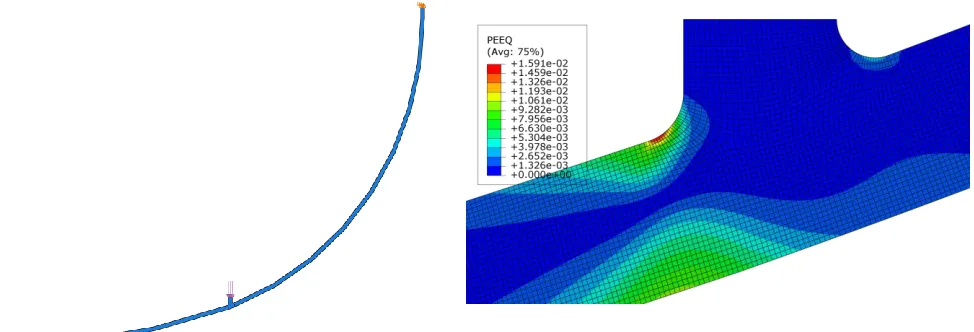
Initial yielding starts at the shell surfaces in vicinity of triple point and propagates through the thickness with increases in load. Figure 8 shows equivalent plastic strain distribution in 60 mm thick torispherical dished end at triple point for load multiplication factor 1.5.
Figure-7 FEM model of dished end
Figure-8 Equivalent plastic strain distribution in triple point region.
Figure 9, 10 and 11 shows load displacement plots, plotted as load multiplier of reference load vs displacement of triple point. Figure 12 shows load displacement plot for limit load analysis for thickness 20 mm, 40 mm and 60 mm. Plastic load computed from TI criterion are equal or lower than limit loads and suggest that effect of strain hardening is not accounted in plastic collapse load, whereas in case of TES criterion, effect of strain hardening is appearing to be accounted in case of thin torispherical dished end plastic load computation, while for more thick dished ends, effect of strain hardening is small.
Figure 13 shows radius of curvature of plastic work plotted against load multiplier for thickness 20 mm. Peak radius of curvature is attained for load multiplier 1.903 and radius of curvature becomes zero for load multiplier 2.006. Hence collapse load multiplier as per plastic work curvature criterion (PWC) is 2.006. Similarly, figure 14 shows radius of curvature of plastic work plotted against load multiplier for thickness 40 mm, and peak radius of curvature is attained at load multiplier 1.913 and becomes zero at 1.943. Collapse load multiplier as per plastic work curvature criterion is 1.943. Figure 15 shows that plastic work radius of curvature plot against load multiplier for thickness 60 mm. Before maximum radius of curvature occurs at load 2.183, a small peak is observed at load multiplier 1.814. Plastic collapse load is determined for this small peak and load multiplier for which this small peak become zero is 1.849.
Table-1 shows the collapse load of collapse load calculated with different plastic load criterions
Table 1: Collapse load for as per different criterions.
Collapse loads
Figure-9 Load displacement plot for dished end with 20 mm thickness
Figure-10 Load displacement plot for dished end with 40 mm thickness
Figure-11 Load displacement plot for dished end with 60 mm thickness
Figure-13 Radius of curvature-load plot for dished end with 20 mm thickness
Figure-14 Radius of curvature-load plot for dished end with 40 mm thickness
Figure-15 Radius of curvature-load plot for dished
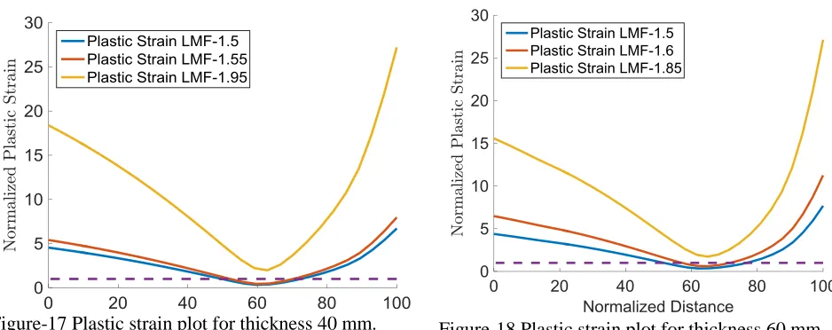
end with 60 mm thicknessFigure-17 Plastic strain plot for thickness 40 mm. Figure-18 Plastic strain plot for thickness 60 mm.
Figure 16, 17 and 18 shows equivalent plastic strain variation across the thickness of critical section for three load multiplication factors for thickness 20 mm, 40 mm and 60 mm respectively. Assuming material with plastic strain less than 0.2 is elastic, plastic strain in plots is normalized with respect to 0.2 percent strain. Similarly distance across the section thickness is normalized to section thickness percentage. For dished end with thickness 20 mm, elastic region is 23.75 percent of section thickness for load multiplication factor 1.5 and reduces to 12.5 percent for load multiplication factor 1.65. For load multiplication factor 2, minimum plastic strain at mid-section is 1.717 times of yield strain. For dished end with thickness 40 mm, elastic region is 22.56 percent of section thickness for load multiplication factor 1.5, and reduced to 18.23 percent for load multiplication factor 1.55. Minimum plastic strain at mid-section is 1.989 times of yield strain at load multiplication factor 1.95. For dished end with thickness 60 mm, elastic region is 24.89 percent of section thickness for load multiplication 1.5, and reduces to 14.34 percentage for load multiplication factor 1.55. For load multiplication factor 1.85, minimum plastic strain at mid-section is 1.73 times of yield strain.
It is see can be see that for collapse load computed from TI, TES criterions, plastic strain is limited in section and part of section remain elastic. These criterions clearly do not account strain hardening effect of material model. However, at for collapse computed by PWC, full section develops significant plastic strain. With further application of loads, due to strain hardening, yield stress increase with increases in plastic strain through yield criterion. This increase in yield stress further enhances the load carrying capacity of structure as seen in load displacement plots.
CONCLUSION
Three method, TI, TES, and PWC are used to compute plastic collapse load of nonlinear elastic plastic analysis. Two geometry configuration are considered, one is simply supported beam under unfirmly distributed load and a torispherical dished end with three different thickness. In cases of beam, plastic collapse load due PWC is 1.92, significantly higher than collapse load computed from TI and TES, However, still 13.2 percent of section still remains elastic at PWC. In case of torispherical dished end, for all thickness cases, plastic load computed from PWC is significantly higher than collapse load computed from TI and TES and complete section undergoes significant plastic straining at PWC collapse load.
ACKNOWLEDGEMENT
REFERENCES