IJEDR1402264
International Journal of Engineering Development and Research (www.ijedr.org)2841
Power Flow Control Using Inter-Line Power Flow
Controller
1
Trivedi Bhavin,
2Nehal Patel,
3Mohammed Irfan Siddiqui,
4Ajit Rathod,
5Shwetal Patel
1PG Student, 2Assistant Professor, 3Assitant Professor, 4Assitant Professor, 5PG Student1
Dept. of Electrical Engineering, Parul Institute of Technology, Vadodara, Gujarat, India
________________________________________________________________________________________________________
Abstract— In the rapid development of the power system, the cost of transmission lines plays a vital role in the network
society. Due to various practical constraints, the transmission lines are often only used for a fraction of it individual limits. To improve the economics of those constraints, one possibility would be to increase the value of the transmission lines by transport large amounts of energy through those lines. One solution to this problem will be a FACTS technology. For series compensation, an Interline Power Flow Controller (IPFC) is voltage source converter based FACTS controller with the unique ability to control the flow of energy between multiple transmission lines. An Objective of the dissertation is to investigate performance of IPFC on the two parallel transmission lines of 400 KV. The effectiveness of the controller on controlling the impedance of the transmission line and hence the power flows on system will be investigate using direct control strategy. IPFC has the capability of exchanging the real and reactive power with the system. The model of power system & controller is implemented using MATLAB software.
Index Terms— Flexible AC Transmission System, Voltage Source Converter (VSC) , Static Synchronous Series
Compensator, Inter-line Power Flow Controller(IPFC)
________________________________________________________________________________________________________
I.INTRODUCTION
As a result of the Flexible AC Transmission System (FACTS) initiative, considerable effort has been spent in recent years on the development of power electronics-based power flow controllers. From a technical approach standpoint, these controllers either use thyristor-switched capacitors and reactors to provide reactive shunt and series compensation, or employ self-commutated inverters as synchronous voltage sources to modify the prevailing transmission line voltage and thereby control power flow. The Interline Power Flow Controller (IPFC) concept proposed in this paper addresses the problem of compensating a number of transmission lines at a given substation. Conventionally, series capacitive compensation (fixed, thyristor-controlled or SSSC-based) is employed to increase the transmittable real power over a given line and also to balance the loading of a normally encountered multi-line transmission system. However, independent of their implementation, series reactive compensators are unable to control the reactive power flow in, and thus the proper load balancing of, the lines. This problem becomes particularly evident in those cases where the ratio of reactive to resistive line impedance (X/R) is relatively low. Series reactive compensation reduces only the effective reactive impedance X and, thus, significantly decreases the effective X/R ratio and thereby increases the reactive power flow and losses in the line. The IPFC scheme proposed provides, together with independently controllable reactive series compensation of each individual line, a capability to directly transfer real power between the compensated lines. This capability makes it possible to: equalize both real and reactive power flow between the lines; transfer power demand from overloaded to under loaded lines; compensate against resistive line voltage drops and the corresponding reactive power demand; increase the effectiveness of the overall compensating system for dynamic disturbances. In other words, the IPFC can potentially provide a highly effective scheme for power transmission management at a multi-line substation.
II. INTER-LINE POWER FLOW CONTROLLER
IJEDR1402264
International Journal of Engineering Development and Research (www.ijedr.org)2842
Fig.1 Simplified Circuit of IPFCA pure series reactive (controllable) compensation in the form of TCSC or SSSC can be used to control or regulate the active power flow in the line; the control of reactive power is not feasible unless active (real) voltage in phase with the line current is not injected. The application of a TCSC (or SSSC with impedance emulation) results in the reduction of net series reactance of the line. However, X/R ratio is reduced significantly and thereby increases the reactive power flow (injected at the receiving end) and losses in the line. The interline power flow controller (IPFC) provides, in addition to the facility for independently controllable reactive (series) compensation of each individual line, a capability to directly transfer or exchange real power between the compensated lines. This is achieved by coupling the series connected VSC in individual lines on the DC side, by connecting all the DC capacitors of individual converters in parallel. Since all the series converters are located inside the substation in close proximity, this is feasible.
III. BASIC PRINCIPLE OF IPFC
In its general form the Interline Power Flow Controller employs a number of dc to ac inverters providing each series compensation for a different line. In other words, the IPFC comprises a number of Static Synchronous Series Compensators. However, within the general concept of the IPFC, the compensating inverters are linked together at their dc terminals, as illustrated in Fig. 2. With this scheme, in addition to providing series reactive compensation, any inverter can be controlled to supply real power to the common dc link from its own transmission line. Thus, an overall surplus power can be made available from the underutilized lines which then can be used by other lines for real power compensation. In this way, some of the inverters, compensating overloaded lines or lines with a heavy burden of reactive power flow, can be equipped with full two-dimensional, reactive and real power control capability, similar to that offered by the UPFC. Evidently, this arrangement mandates the rigorous maintenance of the overall power balance at the common dc terminal by appropriate control action, using the general principle that the under loaded lines are to provide help, in the form of appropriate real power transfer, for the overloaded lines.
IJEDR1402264
International Journal of Engineering Development and Research (www.ijedr.org)2843
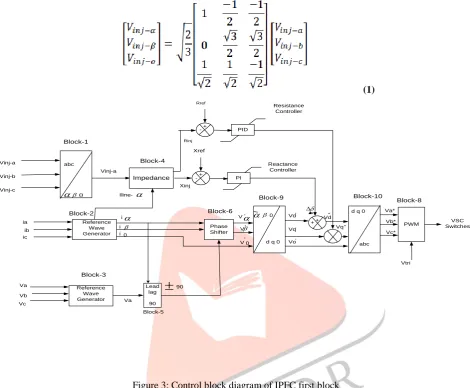
IV. DIRECT CONTROLLERBlock 1 is used to transform the three phase voltage injected by the VSC (Vinj_a, Vinj_b, and Vinj_a) in to the two phases as the equation (1).Block 2 is used to transform the three phase line currents (Ia, Ib and Ic) in to two phase Iα & Iβ similar to equation (1). (1) Phase Shifter abc Reference Wave Generator Reference Wave Generator PWM Lead lag 90 Impedance Reactance Controller PI abc VSC Switches Vtri Vinj-a Vinj-b Vinj-c ia ib ic Va Vb Vc 0
d q 0
+ -+ + i i i 0 Vinj-a Block-1 Block-4 Block-2 Block-3 Block-5 Block-6 Block-9 Block-10 Block-8 0
d q 0 V V V 0 Iline- ‘ ‘ ‘ ‘ ‘ ‘ Vd Vq Vo Va* Vb* Vc* Vd“ Va Xref Xinj
90 Impedance PID -+ Rinj Rref Resistance Controller Vq“Figure 3: Control block diagram of IPFC first block
Block 3 is used to transform the three phase line voltages (Va, Vb and Vc) in to two phase Vα & Vβ similar to equation (1). Block 4 receives positive sequence voltage Vinj-alpha and positive sequence current from Block 2. It computes both injected reactance and resistance into the transmission line and sends them forward to the Reactance control Resistance control block respectively. Block 5 (Lead/ Lag Block) receives the reference signal of the line voltage Vα and from block 3 and the reference signal of the line current Iα from block 2 and computes the 90° phase shift and its sign, whether leading (+1) or lagging (-1) of this angular displacement. Block 6 receives the Iα and Iβ reference signals from block 2.These signals are modulated by the sum of the signals from the DC voltage controller and Lead/ Lag blocks to generate the modified reference signals Vα’ and Vβ’. Block 9 is the α –β – 0 to d – q- 0 transformation block used to convert the two phase reference components in stationary frame Vα’ and Vβ’ to two phase reference component in synchronously rotating frame Vd’ and Vq’ as per the equation (2).
(2)
To regulate the injected reactance, reactance controller is employed and similarly to control injected resistance control is employed. Block 10 receives the modified d- and q- components Vd’ and Vq’ and transform them to three phase coordinated as per the equation (3), these signals are used as the reference signals Va*, Vb* and Vc* of PWM controller and the PWM block provides firing pulses for the VSC switches.
IJEDR1402264
International Journal of Engineering Development and Research (www.ijedr.org)2844
Fig.4 shows the overall control structure of the IPFC Second Control Block system. This block diagram is similar to the block diagram of the First Control Block of IPFC system and has many of the same blocks are reused. This block injects only inductive impedance in to transmission line and it keeps DC link voltage at desired level. In this control block diagram mostly blocks are same as first block except dc voltage regulator which regulates exchange of active power by phase angel of injected voltage in response to error in DC-link via PI controller. Here, DC link voltage is maintained constant.Lead -lag Phase Shifter abc Reference Wave Generator Reference Wave Generator PWM
DC Voltage Controller Reactance Reactance Controller PI abc VSC Switches Vtri PI Vinj-a Vinj-b Vinj-c ia ib ic Va Vb Vc Vdc ref 0
d q 0
+ -+ -+ + i i i 0 Vinj-a Block-1 Block-4 Block-2 Block-3 Block-5 Block-6
Block-9 Block-10 Block-8
0
d q 0 V V V 0 Iline- ‘ ‘ ‘ ‘ ‘ ‘ Vd Vq Vo Va* Vb* Vc* Vd“ Va Xref Xinj
90 Vdc 2Figure 4:Control Block Diagram Of IPFC Second Block
V. SIMULATION AND RESULTS
To investigate the effect of IPFC in power system and study it’s effect of power flow the simplest power system as shown in Fig. 5. This power system is simple 400 KV transmissions System.
Figure 5: Two Parallel Transmission Line
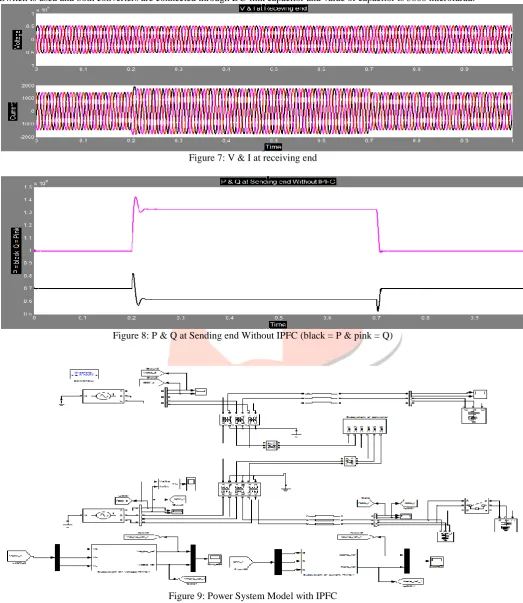
Length of the transmission Line is 80 Km and rating of loads R = 700 MW & L = 300 MVAR. First line has been made overloaded by adding additional load R = 100 MW & L = 200 MVAR through circuit breaker for specific time from 0.2 to 0.7 second. Figure 6 & 7 depicts the Voltage and Current of line-1 at sending and receiving end without IPFC respectively.
IJEDR1402264
International Journal of Engineering Development and Research (www.ijedr.org)2845
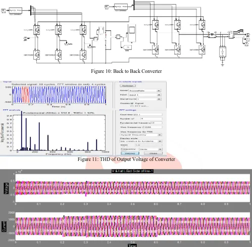
Figure 8 shows active & reactive power without IPFC & its value during overload is 6 × 10^8 Watt & 13 ×10^8 Var respectively. Figure 9 depicts power system model with IPFC Controller. Figure 10 shows IPFC Converter in which IGBT/Diode Switch is used and both converters are connected through DC-link capacitor and value of capacitor is 3000 microfarad.
Figure 7: V & I at receiving end
Figure 8: P & Q at Sending end Without IPFC (black = P & pink = Q)
Figure 9: Power System Model with IPFCIJEDR1402264
International Journal of Engineering Development and Research (www.ijedr.org)2846
implemented during 0.3 to 0.7 seconds & during that time it can be observe that active power is improved from 6 × 10^8 Watt to 7.6 × 10^8 Watt & reactive power is decreased from 13 ×10^8 Var to 10 ×10^8 Var .
Figure 10: Back to Back Converter
Figure 11: THD of Output Voltage of Converter
Figure 12: V & I of line-1 at Sending end After Implementing IPFC
IJEDR1402264
International Journal of Engineering Development and Research (www.ijedr.org)2847
Figure 14: P & Q at Sending end With IPFC ((black = P & pink = Q)
VI. CONCLUSION
In this paper, the detailed model of IPFC was implemented. It has the capable of exchanging the real and reactive power with the system. The performance of the IPFC on the parallel transmission lines was demonstrated. Simulation results show the effectiveness of the controller on controlling the impedance of the transmission line and hence the power flows on the chosen system. From the result we can conclude that IPFC can increase power transfer capability & it is able to maintain voltage profile within allowable limit.
REFERENCES
[1] N.G. Hingorani and L.Gyugyi, “Understanding FACTS: concepts and technology of flexible AC transmission system,” New York, NY: IEEE press, 2000.
[2] Amir Kahyaei , “Analysis of Interline Power Flow Controller (IPFC) Location in Power Transmission Systems”, Research Journal of Applied Sciences, Engineering and Technology, Published: July 25, 2011
[3] J. Muruganandham, Dr. R. Gnanadass, “Performance Analysis of Interline Power Flow Controller for Practical Power System” ,IEEE Students’ Conference on Electrical, Electronics and Computer Science,2012
[4] Jianhong Chen, Tjing T. Lie , D.M.Vilathgamuwa ,“Basic Control of Interline Power Flow Controller”, IEEE 2002 [5] Mr. Jaimin Patel, Mr. A.M.Upadhyay, “Simulation Of Interline Power Flow Controller in Power Transmission System
” ,International Journal for Scientific Research & Development, Vol. 1, Issue 4, 2013
[6] Sasan Salem , Master Thesis " Simulation Of Controller Configurations for Static Synchronous Series Compensator &Interline Power Flow Controller with EMTP-RV" , Concordia University, Canada 2005