A New Control Strategy for PMSG Based
Wind Energy Conversion System
T.Santhana Krishnan1, C.Sharmeela2
AssistantProfessor, Department of EEE, Rajalakshmi Engineering College, Chennai, India1 Assistant Professor, Department of EEE, College of Engineering, Anna University, Chennai, India2
ABSTRACT: In recent days, people migrated towards renewable energy sources to meet their power demand. Among all these renewable energy sources wind energy system is widely preferred because of its pollution free in nature, provides all time energy source and also occupies less space at ground level as compared to solar panels. Reliability and efficiency are two major factors in wind energy conversion system. A high gain Resonant Switched Capacitor (RSC) converter operates at high frequency will eliminate the switching losses and also reduces the size of the passive elements. PSO based MPPT controller can improve the accuracy of which the maximum power transmitted for the time varying wind speed. This method will reduce the time required for convergence and adaptive step size variation is achieved as compared to conventional Hill Climb Search based MPPT controller. The developed power will be applied to AC micro grid with the help of voltage source inverter. Micro grid is a local network supplied with the generated power from wind energy conversion system which eliminates long distance transmission losses and heat losses caused by the transmission lines. The simulation and analysis of the proposed system is carried out in MATLAB Simulink to obtain the system performance which validates its design and working.
KEYWORDS: Wind energy system, Particle Swarm Optimization (PSO), Maximum Power Point Tracking (MPPT), Resonant Switched Capacitor Converter (RSC), Micro grid
.
I. INTRODUCTION
Wind is an attractive renewable energy source which has gained momentum recently. However the generated energy from wind is always fluctuating in nature which may leads to power quality issues and disturbances in loads connected with grid. Recent researches focused on use of Permanent Magnet Synchronous Generator as a wind generator because of its low cost, high efficiency and self-starting ability.
According to the topology concerned simple DC to DC boost converter is used in between diode rectifier and inverter. This topology will give efficiency of about 80% only. So that multilevel DC to DC converter is emerged which can give the efficiency of about 93% but it may lead to large size of components and high switching stress. The High gain Resonant Switched Capacitor (RSC) with multiple stages formed with series and cascade combination will result in efficiency of about 98%.
II.OBJECTIVE
The main objective is to design, simulate and implement Particle swarm optimization technique based MPPT algorithm for wind energy conversion system with high gain resonant converter for micro grid applications. To compare the performance obtained by PSO based MPPT controlled wind energy system with conventional MPPT controlled wind energy system.
III. SYSTEM OVERVIEW
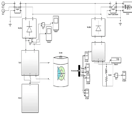
Fig.1 illustrates the schematic diagram of the wind energy conversion system. This system supplies to a micro grid and contains wind turbine, Permanent Magnet Synchronous Generator (PMSG), rectifier, high gain Resonant Switched Capacitor (RSC) converter, Particle Swarm Optimization (PSO) based Maximum Power Point Tracking (MPPT) controller and an inverter.
Figure 1 Block diagram of proposed system. A. Wind turbine Modelling
Wind turbine converts the kinetic energy of wind into mechanical energy. There are two major types of wind turbines Horizontal Axis Wind Turbine (HAWT) and Vertical Axis Wind Turbine (VAWT). The HAWT is widely used for high power applications. Here fixed pitch variable speed wind turbine is modelled with parameters power coefficient (Cp) and tip speed ratio (λ). The power equation will be,
Pm= 0.5ρACp(λ, β) Vw3 (1)
Where Cp (λ, β) = power coe cient, λ = the tip speed ratio, and β = pitch angle fixed to 0o. Tip speed ratio can be calculated as,
λ = Rωr/ Vw (2)
Where ωr is the angular speed, R is the turbine radius and Vw is the wind velocity. Power coefficient can be obtained
as,
Cp(λ, β) = 0.5(116(1/ λ)-0.4 β-5) e-(21/ λi) (3)
Figure 2 CpVs λ characteristics
The dynamic equation of wind turbine is given as
dωr / dt = (1/J) [ Tm -TL - Fωr ] (5)
Where J is the system inertia, F is the viscous friction coefficient, Tm is torque developed by the turbine, TL is the
torque due to load. B. PMSG modelling
Among various electric generators, PMSG is preferred due to its high efficiency, reliability, power density, gearless construction, light weight and self excitation features. This paper uses simplified model of the PMSG. The source EMF (ew) is proportional to the generator speed (ωm) and the equivalent resistance has a value of twice the per phase
resistance of the generator.
ew = Kwωm (6)
Neglecting the damping and friction, the mechanical dynamics can be reduced to
J dωm/dt = Tm – Te (7)
Te = Pe / ωm = ew idc / ωm=Kw idc (8)
Where Kw is the generator EMF constant. Tm is the turbine mechanical torque and Te is electrical torque.
C. Diode Rectifier
Figure 3 Simulation model of diode rectifier D. Resonant Converter
This paper proposes a multistage resonant converter which offers higher voltage gain. Here the proposed converter is modelled based ZCS (Zero Current Switching) quasi resonant converter principle also known as Resonant Switched Capacitor (RSC) converter. Here three stage resonant converter is proposed.
The RSC converter is composed of six resonant capacitors (Crt1, Crt2, Crt3, Crb1, Crb2 and Crb3), two output filter capacitors (Cto and Cbo), six resonant inductors (Lrt1, Lrt2, Lrt3, Lrb1, Lrb2 and Lrb3), two output resonant inductors (Lto and Lbo), eight diodes (Dt1, Dt2, Dt3, Dto, Db1, Db2, Db3 and Dbo), and six switches (St1, St2, St3, Sb1, Sb2 and Sb3). In this paper, subscripts “t” and “b” represent the corresponding variables to the circuit components at the top and bottom cells, respectively. The switches (St1, St2, St3) and (Sb1, Sb2, Sb3) are controlled complementarily with a 50% duty cycle to minimize the conduction losses in the power devices and passive components.
Figure 4 Three stage resonant converter
Vo = (2k+1 − 1) Vs (9)
For three stage converter the output voltage will be
Vo = 15 Vs (10)
Mode I: Sb1, Sb2 and Sb3 are ON, whereas St1, St2 and St3 are OFF and the diodes Db1 Db2 and Db3 are reverse biased. The charging currents flow through Dt1-Sb1-Dt2-Sb2-Dt3-Sb3, Crt1, Crt2 and Crt3 are charged, whereas Crb1, Crb2 and Crb3 are discharged to Cbo in the bottom cell. Sb1, Sb2 and Sb3 can then be OFF under the zero-current condition
Mode II: In this mode, all the switches and diodes are turned OFF, Therefore, the inductor currents are equal to zero. The resonant capacitor voltages of Crt1, Crt2, Crt3 Crb1, Crb2 and Crb3 are unchanged. The output capacitor voltages of Cto and Cbo are discharged to the load.
Mode III: St1, St2 and St3 are turned ON, while Sb1, Sb2 and Sb3 are OFF.Crt1, Crt2 and Crt3 are discharged to Cto, whereas Crb1, Crb2 and Crb3 are charged. The charging currents flow through St1-Lrt1-St2-Lrt2-St3-Lrt3-Lto-Dto.
E. PSO based MPPT controller
A large number of MPPT techniques for WECS have been studied, they can be divided into three main methods: Hill Climb Search (HSC) control, Tip Speed Ratio (TSR) control and Power Signal Feedback (PSF) control.
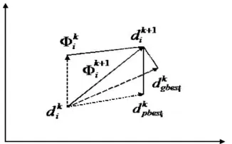
Figure 5 Modification of a searching point by PSO.
Particle swarm optimization is a computational method that optimizes a problem by iteratively improves a candidate solution with regard to a given measure of quality. It starts with a group of random potential solutions, which are called particles. These particles fly around in a multidimensional search space searching for the optimum solution by adjusting their positions depending on their own experience as well as the experience of the other particles. To be realized as a MPPT algorithm, the particle position in PSO represents the duty-cycle, the velocity is the step-size of the duty-cycle and the objective function is maximizing the converter power. As depicted in Fig. 5, the particle position and velocity are updated iteratively based on the following two equations:
(11)
Where w is defined as the momentum factor, r1 and r2 are two random values between (0.1), c1 and c2 are positive constants known as acceleration constants.
Figure 6 PSO based MPPT controller F. Inverter Model
Figure 7 Simulation model of voltage source inverter G. Micro grid Modelling
A new concept in power generation is a micro grid. A micro grid involves connecting several small alternative power sources in addition to the main grid on a particular site. Some examples where it could be used would be an office block, industrial site or shopping centre. Little is known about micro grid behaviour on the whole. Some models exist which describe the components of a micro grid, although to date a successful model of an entire micro grid system has not been developed.
Efficiency of conventional grid is very low as compared to Micro grid because large amount of energy in the form of heat is wasted in conventional grid. Three load to be implemented for micro grid are Battery, PMDC motor, Heater.
IV.SIMULATION RESULTS AND DISCUSSION
The simulation results of this section are generated using MATLAB/Simulink simulation software.
TABLE I Components Symbols Values 1.WIND TURBINE
Radius of turbine R 2.3m
Air density ρ 1.08kg/m3
Inertia J 0.01kg.m2 2. PMSG
Winding resistance Rw 4.2Ὡ
EMF constant Kw 10.48V.s/rad
3.RESONANT CONVERTER
Resonant capacitors Crt1-Crt3 200µF Resonant capacitors Crb1-Crb3 200µF Output Capacitors Ct0 and Cb0 200µF Resonant inductors Lrt1-Lrt3 14µH Resonant inductors Lrb1-Lrb3 14µH Output inductors Lt0 and Lb0 14µH 4.PSO
Momentum factor w 0.15 Positive constants c1 and c2 0.5 and 1.6
The proposed RSC converter was implemented on a 2kW PMSG to verify the theoretical developments presented previously. The proposed converter was designed to boost a 100V input to the maximum output voltage of 1500 V. The switching frequency is about 2.8 kHz. Table I lists the specifications of the capacitors and inductors.
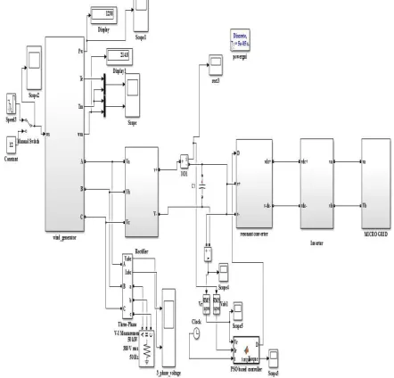
Figure 10 Simulation circuit of three stage resonant converter
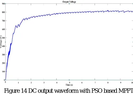
Here the proposed model of wind turbine will results in voltage range of 30V to 60V which is boosted up with the help of resonant converter upto 15 times the input voltage (i.e) 450V to 900V.
Figure 11 Output of resonant converter for 100V input
Figure 12 Duty cycle variation by simple P and O algorithm and corresponding PWM pulses
Whereas PSO based MPPT controller will result in adaptive step change in duty cycle which is shown in comparison with conventional method as,
Table 1 Duty cycle variation with P and O and PSO algorithm
S.No
Duty cycle variation with P and O algorithm Duty cycle variation with PSO algorithm
Time (s) Duty Cycle Time (s) Duty cycle
1
0.0002 0.75 0.0002 0.54
2
0.0003 0.75 0.0003 0.54
3 0.01 0.65 0.01 0.53 4 0.03 0.55 0.03 0.527539 5
0.05 0.45 0.05 0.466231
6
0.0865 0.6 0.0865 0.540641
7
0.0866 0.45 0.0866 0.457063
8
0.0867 0.45 0.0867 0.459011
9
0.0868 0.7 0.0868 0.540085
10
0.087 0.5 0.087 0.456671
11
0.0875 0.5 0.0875 0.459663
12
0.088 0.65 0.088 0.538993
13 0.09 0.75 0.09 0.539386 14 0.095 0.65 0.095 0.539412 15 0.1 0.75 0.1 0.541255 16 0.15 0.7 0.15 0.546128 17 0.16 0.6 0.16 0.536886 18 0.17 0.75 0.17 0.546886 19 0.18 0.5 0.18 0.452548 20
0.19 0.55 0.19 0.549236 Table 1 represents the values of duty cycle variations with P and O and PSO based controller.
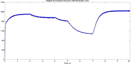
By this control technique we can obtain constant voltage range for time varying input wind speed. The output waveform without MPPT controller will be
Whereas the output with MPPT controller will results in
Figure 14 DC output waveform with PSO based MPPT
The power variation curve is obtained with P and O controller and PSO controller is compared with the uncontrolled system is shown in figure 15 as ,
Figure 15 Comparison of output power
The efficiency comparison table is shown in Table 2 with percent improvement in efiiciency without any controller Table 2 Ouput power comparison with efficiency
Method Efficiency (%) Percent improvement Without MPPT
With HCS Based MPPT PSO based MPPT controller
84.8 91.56
96.31 -
6.76
Figure 16 Micro grid output
Figure 16 represents the output of PMDC motor, one of the loads connected with micro grid
V.CONCLUSION AND FURURE SCOPE
Various WECS were modelled to meet the power demand whereas PMSG based WECS is widely preferred for variable speed wind turbine to achieve better efficiency. The high gain resonant converter is modelled in such a way that it will provide efficiency of about 98% at steady state as compared to other converters. The adaptive step change achieved by PSO based MPPT technique will result in less steady state oscillation in output waveform as compared to other methods. Accuracy and reliability is achieved by this overall system.
REFERENCES
1. Abdullah .M. A, Yatim A.H.M, Tan C.W, Samosir A.S,"A review of maximum power point tracking algorithms for wind energy systems," Renewable and Sustainable Energy Reviews, vol. 16, pp. 3220-3227, December 2014
2. Amir Parastar, Jul-Ki Seok, “High-Gain Resonant Switched-Capacitor Cell-Based DC/DC Converter for Offshore Wind Energy Systems”, IEEE transactions on power electronics, vol.30, no.2 February 2015,
3. Ian Laird, Ian Laird and Dylan Dah Chuan Lu, “High Step-Up DC/DC Topology and MPPT Algorithm for Use with a Thermoelectric Generator” IEEE Transactions on Power Electronics, vol 28, no 7, July 2013.
4. Ishaque .K, Johor Bahru, Salam .Z, Amjad .M, Mekhilef .S,“ An Improved Particle Swarm Optimization (PSO) based MPPT for PV with Reduced Steady State Oscillation," Power Electronics, IEEE Transactions on, vol. 26, Issue 8, September 2014.
5. Kaiqin Yan, Jai Hou, Xiaoyong Ren,and Xinbo Ruan, “Self-Oscillating Contactless Resonant Converter With Phase Detection Contactless Current Transformer”, IEEE transactions on Power Electronics, vol.29, no. 8, August 2014.
6. Melícioa .R, Mendes V.M.F , Catalão J.P.S,“Power Converter Topologies for Wind Energy Conversion Systems: Integrated Modelling, Control Strategy and Performance Simulation” Received 24 October 2008; received in revised form 13 February 2010
7. Z. Qian, O. Abdel-Rahman, H. Al-trash, and I. Batarseh,(2010) “Modeling and control of three-port DC/DC converter interface for satellite applications, IEEE Trans. Power Electron., vol. 25, no. 3, pp. 637–649, March 2010.
8. Zhijun Qian, Osama Abdel- Rahman and Issa Batarseh,(2010)“An Integrated Four-Port DC/DC Converter 9. Renewable Energy Applications,”IEEE Trans. Power Electron. vol.25, no.7, pp.1877-1887, July 2010
10. Thanh Hai Nguyen, Dong-Choon Lee and Chan-Ki Kim, “A Series-Connected Topology of a Diode Rectifier and a Voltage-Source Converter for an HVDC Transmission System”, IEEE Transactions on Power Electronics, Vol.29, no. 4, April 2014.
11. Yu-Seop Park, Min-Mo Koo, Seok-Myeong Jang, Jang-Young Choi, and Dae-Joon You, “Performance Evaluation of Radial- and Axial-Flux PM Wind Power Generators With Mechanical Energy Storage
12. System”, IEEE Transaction on Energy Conversions, vol. 30, no. 1, March 2015
13. Wu Chen , Nanjing, Xiaogang Wu, Liangzhong Yao and Wei Jiang, “A Step-up Resonant Converter for Grid Connected Renewable Energy Sources,” IEEE Transaction on Power Electronics, IEEE Transactions on Vol.30 , Issue: 6 ,no. 1, pp. 331–339, October 2015
![2 [(2,4 Dimethylphenyl)iminomethyl] 6 methylphenol](data:image/gif;base64,R0lGODlhAQABAIAAAP///wAAACH5BAEAAAAALAAAAAABAAEAAAICRAEAOw==)