IJEDR1602314
International Journal of Engineering Development and Research (www.ijedr.org)1
Modeling and Simulation of Cylindrical Gate OTFT
and its Application in Digital Circuits
1 Anshu Singh, 2 Vishal Ramola 1M.Tech Student, 2Assitant Professor
1VLSI DESIGN,
1 Faculty of Technology, Uttarakhand Technical University, Dehradun, INDIA
________________________________________________________________________________________________________
Abstract –Carbon based electronics (i.e. organic molecules) has opened the new gates and unexplored possibilities of swiftly-growing industrial field in organic electronics market transporting to this area novel dimension of flexibility and thinness.. A lot of novel performs are anticipated for boosting the device and circuit performance. CG-OTFT i.e. cylindrical gate organic thin film transistors are one of these techniques which are used for the enhancement of the OSCs based devices and circuits application. Analytical modeling of CG-OTFT is done in different regions. In this research paper depth analysis of the CG-OTFT for different modes of operation (Linear and Saturation region) in terms of Drin current Id, ION/IOFF, Vth, µ, and SS is done. In this paper electrical behavior of cylindrical OTFT is examined using 2D
Atlas numerical simulators. Moreover this, cylindrical organic thin film transistor are examined. Additionally, we introduce p-type organic inverter-circuits with DLL and ZVLL topology using CG structures. Finally we obtained the Voltage Transfer Characteristics and Transient Response of the Cylindrical Gate Inverter in DLL and ZVLL Mode.
Index Terms – Organic Semiconductor Material (OSC), Organic Thin Film Transistor (OTFT), Cylindrical Gate-OTFT (CG-OTFT), Diode-Load-Logic (DLL, Zero-Vgs-Load-Logic (ZVLL).
________________________________________________________________________________________________________
I.INTRODUCTION
Transistor having organic semiconductor (small molecules /conducting polymers) as active layer to current flow. The transistors quickly supplanted vacuum tubes, which are cumbersome and high in power utilization, and turned into the fundamental components of incorporated circuits. The transistors comprise of diffused deplete and source locales in mass semiconducting materials. The most considered and broadly utilized material for device is without doubt is Si. Its comparable semiconductor properties and its related costs (Raw material/ Fabrication) make it a perfect possibility for most of the requirements of today application. Researchers realized in 1970 that some applications, like displays, RFID tags, required large array of low cost electronics which was not possible with silicon. This marked the advent of amorphous silicon TFTs (a-Si-TFTs). Carbon based semiconductors permitted researchers and specialists to create gadgets with advance elements and diminished costs, creating this innovation turn into a head contender for a few divisions of electronics [1].
OSCs can be produced and handled at normal conditions (temperature and humidity), building their creation simpler and less expensive than for routine Si and inorganic-semiconductors; they can be flexible, adaptable, transparent and created over substantial ranges as well as on non planar-geometry; totally plastic-gadgets can be figured it out. Their exhibitions, contrasted with Si, are yet low-grade: transporter versatility that is carrier mobility is range of size lower, regardless of the fact that this to a great extent expanded in the most recent years. Discovery and Development of the conducting polymers (Polyacetylene-pure state is poor conductor + I2) by Dr. H. Shirakawa, Dr .Alan G .MacDiarmid and Dr. Alan. J. Heeger created a new research field in 1976 [2]. Organic Materials: Polymers: Polythiophene group (P3HT, P3OT, and P3AT) and Small Molecules: Pentacene, CuPc, F16CuPC are generally used in the OSCs layers. Nobel Prize in Chemistry in 2000 was given for the same [3].
Polymeric transistors are transistors that use organic molecules, conducting polymers rather than silicon for their active material. Polymer materials have advantage of being amendable to specific deposition techniques. High performance requires high ordering, especially in the vicinity of the insulator- OSC interface. The OTFT structure the very premise of flexible devices, which is one of the promising innovations. Flexible electronics will open up a wide and creative application field for different sensors, display panels, e-skin, e-paper and RFID tags.
The growth of advance electronics has raise to understanding of devices with different geometries for different application. For example, cylindrical geometries are regularly used to get device-size lessening without the event of short channel impacts, similar to conventional MOSFET [4]. Cylindrical geometry has been utilized where long yarn-like structures are required for adaptable hardware and e-material application. Cylindrical geometry is intended for size lessening with great bowing strength, hysteresis free operation and high pressing thickness, too. This field has as of newly in a solid attention for various purpose that are possibly because of this new innovation: Advance material textile scheme for biomedical observing capacities, man-machine interfaces, and so on.
IJEDR1602314
International Journal of Engineering Development and Research (www.ijedr.org)1791
Fig. 1 Schematic of Cylindrical Gate Organic Thin Film Transistor.A cylindrical organic thin film transistor does not have body effect and short channel effect as conventional MOSFETs or inorganic transistors have. Cylindrical organic thin film transistors can be made either on a solitary substrate of yarn or at the crossing point of two confined yarn. Up-to-date, only a few steps have been done towards realization of organic-based e-textile devices [5].
This paper is divided into SIX sections, including the current introductory Section I, in this part basic idea of organic electronics and organic thin film transistor, as well as CG-OTFT illustrated. This is followed by Section II where modeling of cylindrical gate OTFT is discussed. After this simulation setup is discussed and this employed for the analyses of the performance of CG-OTFT in section III. In section IV discussed the electrical characteristics of the device and extraction of parameters of CG-OTFT. After this the Section V makes the discussion about the implementation of organic inverter based on CG-OTFT, and also discuss about DLL and ZVLL configuration for the operation of CG-OTFT inverter circuits. Finally, important conclusions about the of the recommended work in brief have been discussed in Section VI.
II. MODELING: CG-OTFT
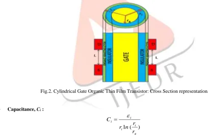
Analytical model has been derived by considering cross section of cylindrical gate OTFT structure as shown in Fig. 2.
Fig.2. Cylindrical Gate Organic Thin Film Transistor: Cross Section representation.
Capacitance, Ci :
)
(
1
g i i
i i
r
r
n
r
C
(1) here, ri = insulator radius, rg = gate radius, εi = dielectric permittivity (3ε0), ε0 = 8.85
10-12f/m2 Channel Width, Z:
r
i
Z
2
(2)
Channel Length, L: (For cylindrical OTFT)
Z
L
(3)IJEDR1602314
International Journal of Engineering Development and Research (www.ijedr.org)1792
2 ,2
1
d d th g i lind
V
V
V
V
L
C
Z
I
(4)
22
1
ln
2
d d th g g i iV
V
V
V
r
r
L
(5)
g i i lin dr
r
L
I
ln
2
,
2 ) ( 2 d S d d S d th g I R V I R V V V (6)here, Vg = gate voltage, Vd = drain voltage, µ = mobility, Vth = threshold voltage, RS = contact resistance.
Saturation Drain Current:
2th g i
dsat
V
V
L
C
Z
I
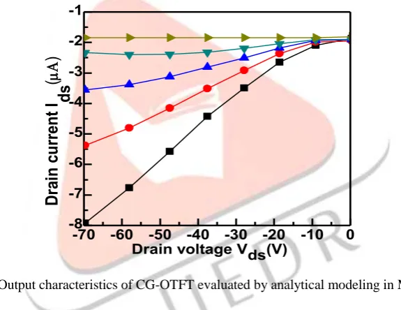
(7)Figure 3 shows the output characteristics of cylindrical gate OTFT calculated by analytical modeling in MATLAB [6].
Fig.3. Output characteristics of CG-OTFT evaluated by analytical modeling in Matlab
III. SIMULATION SETUP
The CG-OTFT device that we have used for our simulation purpose has a channel length of (L) of 100µm and the width of the channel (Z) is 100µm because for cylindrical OTFTs Z=L. The p-type OSC material named Pantacene (small molecules OSCs organic material) with the mobility (µ= 0.15–5.0 (cm2/V s)) and ON/OFF Current ratio (I
ON/IOFF= 103–109) is used in OSC layer. The Gate used here is of Aluminum. Gold is used as a source/drain contact; Al2O3 is used for insulator layer material.
TABLE I. DIMENSIONS OF CYLINDRICAL GATE DEVICE FOR ANALYSIS
Usage Material Thickness
Gate Al 10 nm
Insulator Thickness Al2O3 5 nm
Source/Drain Contact Gold (Au) 20 nm Organic Semiconductor Pentacene 25 nm
Distance between S/D Air 20 nm
The analysis of cylindrical gate OTFT device is accomplished by state of the commercial standard ATLAS 2-D numerical device simulator by Silvaco INC [7]. Atlas simulator uses the Poole-Frenkel model which is a type of mobility model for analyzing the electrical behavior of the device. That model can be illustrated as:
E
kT
kT
E
0exp
(8)-70 -60 -50 -40 -30 -20 -10 0
-8 -7 -6 -5 -4 -3 -2 -1
D
ra
in c
urre
nt
I ds
(
)
IJEDR1602314
International Journal of Engineering Development and Research (www.ijedr.org)1793
Here µ (E) is the field mobility, E is the electric-field, and µ0 is use to describe the field-mobility at No applied-bias. The Δgrants the sign of the creation energy, whereas β is factor of Hole Poole-Frenkel and γ is the fitting parameter. This model describes the method of conduction in the gadget which is because of the thermal-excitation of the strikes charge-carriers in an increased electric field. On every occasion when the Vg is enhancing, the µ as well as also rises therefore illumination the hopping carrying method in the OTFT’s device
IV. CG-OTFT:PERFORMANCE PARAMETER EXTRACTION &ELECTRICAL CHARACTERISTICS
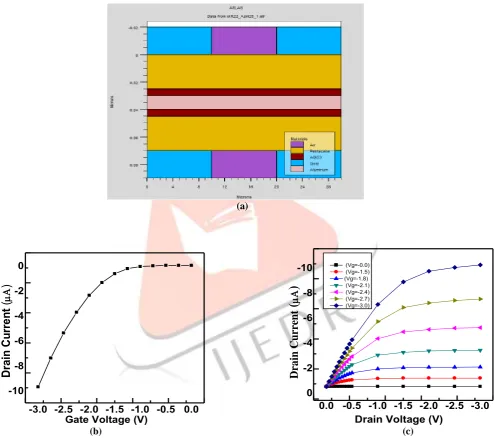
The response of the OTFT based on Cylindrical Gate using Pentacene as OSC material together with the simulated structure of the device is shown in Fig. 4 (a). It is followed by two characteristics I V/s V curves of the device which includes the voltage-transfer curve shown in Fig. 4 (b) and the output curve in Fig. 4 (c).
(a)
(b) (c)
Fig.4. Schematic structure and characteristics of CG- OTFT (a) Structure of the device, (b) Transfer characteristic, (c) Output characteristics.
A Table II shows the Extracted performance parameter of simulated cylindrical gate OTFT.
Table II. CG-OTFT: simulated data
Parameters Name Simulated Data
Threshold Voltage Vt (V) -1.94
Sub-threshold Slope S.S. (V/Dec.) 0.106
Current Ratio (ION/IOFF) 7.05
-3.0 -2.5 -2.0 -1.5 -1.0 -0.5 0.0 -10
-8 -6 -4 -2 0
Dr
ai
n Cu
rr
en
t
(
)
Gate Voltage (V)
0.0 -0.5 -1.0 -1.5 -2.0 -2.5 -3.0 0
-2 -4 -6 -8 -10
Dr
a
in
Curr
ent
(
)
Drain Voltage (V)
IJEDR1602314
International Journal of Engineering Development and Research (www.ijedr.org)1794
Parameters Name Simulated Data
Field Effect Mobility µ (cm2/Vs) 0.04
Transconductance gm 9.23
10-6V. ORGANIC INVERTER BASED ON CYLINDRICAL GATE ORGANIC THIN FILM TRANSISTOR.
A complementary circuit is viewed as the mainly essential circuit component in CMOS innovation. This segment investigates the execution of different complementary circuits that include unlike device arrangement.
Mainly organic complementary (inverter) circuits build use of holes based (p-type) designs merely, because of lower instability and mobility of their n-type complements. The electron based (n-type) transistors are further perceptive to air, moisture and oxygen than holes based (p-types). Surrounded by existing (p-type) OSCs, pentacene be the favorite OSC. The inverter circuit actualize into this effort in various arrangements depend on just p-type gadgets in order to accomplish better execution. The two different configurations i.e. Diode-Load Logic (DLL) and Zero-Vgs-Load Logic (ZVLL) are used for investigation of behavior of inverters (organic) with dynamic and static behaviors using Cylindrical Gate CG-OTFT. It is examined that CG based inverters circuit in distinct designs go one better than the DG and SG. To make sure the best possible function of inverter circuit, some dependability focuses' ought to be considered, particularly; the propagation delay and noise margin [8].
Uncomplicated circuit design, operational robustness, less static power utilization factors are chief benefits of organic (complementary) inverter. Inorganic and/or organic transistor inverter circuits have been considered by a few scientists. With the aim of develop organic inverter circuits, two methodologies are accounted: firstly integrate p and n-type or am-bipolar transistors and secondly two identical transistors are utilizing onto a same substrate. On the other hand, trouble in getting an appropriate material for n-channel TFT drove the specialists to recommend the p-organic inverter.
Basically the single gate (SG) OTFT inverter circuits are represented as in the DLL mode and ZVLL mode are shown in the Fig.5. In a conventional complementary MOS circuit, Pull down system with n-type OTFT [9] is replaced with a single n type OTFT. Configuring them together to perform a particular operation. On contrary to this approach the second method focuses on the deposition of the whole circuit in a single wafer surface to reduce the inter -connects.
Fig.5.SG OTFT inverter based on (a) DLL (b) ZVLL
Now the performance of organic inverter circuit in DLL and ZVLL mode are evaluated using CG-OTFTs. In DLL arrangement, to keep constant Ids, Drain and Gate of load transistor are shorted like revealed in Fig.6. Distinct ZVLL arrangement shown in Fig.7, for enhancement-mode and kindly depletion-mode transistors DLL arrangement is well-suited. This category of logic, so, displays more strength and provides more rapidly circuits.
Fig.6.CG OTFT inverter based onDLL Mode. Fig.7.CG OTFT inverter based onDLL Mode.
On the other hand, in contrast to ZVLL arrangement, the gain and voltage swing are poorer in DLL, seeing as, the pull-down set-up always residue in ON condition to facilitate opposes the VOL (output-low-voltage) to achieve ground stage.
IJEDR1602314
International Journal of Engineering Development and Research (www.ijedr.org)1795
and supply of VDD = 10 V is applied. Voltage transfer characteristics of CG-OTFT based inverter circuit are shown in Fig.8 (a) in DLL mode and (b) in ZVLL mode.
(a) (b)
Fig.8. VTCs of Cylindrical-Gate inverter circuit at VDD=10V (a) DLL mode (b) ZVLL mode.
It is analyzed from VTC (voltage-transfer-characteristics) shown in Fig.8 (a) and (b), that the VOUT swing for CG-device using DLL configuration is higher as comparable to ZVLL configuration logics of the organic inverter circuits.
Figure 9(a) and 9(b) illustrate the transient responses of DLL and ZVLL inverter circuits, respectively. Table III precise the performance parameters of CG and their complementary (inverter) circuits in ZVLL and DLL configuration. Additionally, Myny et al. [10] recognized that DLL circuits are relatively faster and more quickly than ZVLL circuit, while, ZVLL inverters show superior static performance. Comparison along with inverter circuits demonstrates that the whole performance of Zero-Vgs-Load Logic is better in contrast to Diode- Load Logic configuration. On the other hand, CG-OTFTs can out-perform in gain, propagation delay and voltage swing since its lower Vth and higher ION/IOFF ratio.
(a) (b)
Fig.9. Transient Response of Cylindrical-Gate inverter circuit in (a) DLL mode (b) ZVLL mode
For that reason, application of organic inverter based on CG-OTFT be capable of consider as a practical alternative to enhance the supremacy of digital electronics structure block for bigger integration keen on digital description except at the expenditure of additional power-consumption.
TABLE III.EXTRACTEDPERFORMANCEPARAMETEROFCG-OTFT:
Mode VDD VOH VIH VOL VIL NMH NML
DLL 10 8 7.5 0.5 4 1.5 3.5
ZVLL 10 9 8 0.5 5 1 4.5
VI. Conclusion
In this paper we have done the modeling and simulation of the CG-OTFT device. This device is based on the p-type small molecule OSC material i.e. Pentacene material. We obtained the proposed model of OTFTs with Cylindrical geometry, in which geometry of the gate is cylindrical. Analytical Modeling of CG-OTFT done with the two different regions such as Linear and Saturation region. We obtained the Drain currents in these two regions and made a modeling structure of CG-OTFT. In simulation part we achieved an 2D structure of CG-OTFT device with their transfer and output characteristics, and it is clear
0 2 4 6 8 10
1 2 3 4 5 6 7 8 9
VO
U
T(
V
)
V
IN (V)
0 2 4 6 8 10
0 2 4 6 8 10
V
OUT
(V)
VIN (V)
0 1 2 3 4
0 2 4 6 8 10
Voltages (V)
Transient Time (ms)
VIN VOUT
0 1 2 3 4
0 2 4 6 8 10
V
olt
age
(V
)
Transient Time (ms)
IJEDR1602314
International Journal of Engineering Development and Research (www.ijedr.org)1796
from the extracted performance parameters and characteristics of CG-OTFT that cylindrical gate mode is superior than the planar device structure. After this a digital circuit application is implemented with the help of cylindrical gate OTFT i.e. we implemented the organic inverter based on CG-OTFT in two different configurations. DLL and ZVLL mode are utilized to get the inverter circuit. And from the extracted parameters and VTCs and output curve of this inverter we analyzed that DLL circuits are relatively faster and more quickly than ZVLL circuit, while, ZVLL inverters show superior static performance.REFERENCES
[1] B. Kumar, B. K. Kaushik and Y. S. Negi, “Organic thin film transistors: Structure, models, materials, fabrication, and applications: A review”, Polymer Review, vol. 54, no. 1, pp. 33-111, Sept. 2013.
[2] H.Shirakawa, E.J.Louis, A.G.MacDiarmid, C.K.Chiang and A.J.Heeger, “Electrical conductivity of doped acetylene,” J Chem Soc Chem Commun, pp.578–580, 1977.
[3] NOBEL e-Museum, www.nobel.se/index.html, (2003).
[4] C. P. Auth and J.D.Plummer, ʻʻScaling theory for cylindrical, fully depleted, Surrounding-gate MOSFETs,” IEEE, Electron Device Lett, vol.18, no.2, pp.74-76, Feb.1997.
[5] Simone Locci, Maurizio Maccioni, Emanuele Orgiu, and Annalisa Bonfiglio, ʻʻAn analytical model for cylindrical thin-film transistors,” IEEE Trans. on electron devices, vol. 54, no. 9, pp. 2362-2368, Sep. 2007.
[6] G. Horowitz and P. Delannoy, “An analytical model for organic-based thin-film transistors,” J. Appl. Phys., vol. 70, no. 1, p. 469, 1991.
[7] ATLAS User’s Manual Device Simulation Software. Silvaco International Ltd., Santa Clara, USA, 2014.
[8] B. Kumar, B. K. Kaushik and Y. S. Negi, “Static and dynamic characteristics of dual gate organic TFT based NAND and NOR circuits”, Journal of Computational Electronics, vol. 13, no. 3, pp. 1-12, Sept. 2014.