Abstract — This paper considers the control of a 7-leg back-to-back Voltage Source Inverter (VSI) arrangement feeding a 4-wire load from a 3-phase Permanent Magnet Synchronous Generator (PMSG) operating at variable speed. The PMSG is controlled using a sensorless Model Reference Adaptive System (MRAS) to obtain the rotor position angle. The 7-leg converter is regulated using Resonant Controllers (RCs) at the load side and self-tuning resonant controllers at the generator side. The control system is augmented by a feed-forward compensation algorithm which improves the dynamic performance during transients. Experimental results, obtained from a prototype, are presented and discussed.
Index Terms— AC-AC Power Convertion, Power generation control,Converters,Variable speed generation.
I. INTRODUCTION
ariable speed operation of generation systems has several advantages which are well reported in the literature. For instance more energy capture in wind generators [1]; higher efficiency of diesel engines, which can be operated at the optimum power/fuel consumption ratio [2]; less stress in the mechanical components; smaller portable generation systems [3]; etc. To connect a 4-wire load (e.g. an off-grid residential load) to a 3-phase variable-speed generator, several power converter topologies are feasible [4]–[8]. For instance a conventional 3-leg back-to-back voltage source converter connected to a -Y transformer can be used. The star-connected secondary of the transformer is then used to allow the circulation of zero sequence current through the load. However, this is a bulky solution with a low power density.
Another alternative is to use a conventional back-to-back converter with the neutral point of the load connected to the middle of a split capacitor bank in the dc-link. The main problem of this approach is that relatively large capacitors are required to minimise the ripple [8]. A different topology is presented in [7], where a 4-leg matrix converter is proposed to
Manuscript received January 2, 2014; revised May 7, 2014, September 30, 2014 and January 7, 2015; accepted January 26, 2015.
Copyright © 2015 IEEE. Personal use of this material is permitted. However, permission to use this material for any other purposes must be obtained from the IEEE by sending a request to [email protected].
This work was funded by Fondecyt Chile under Contract 1140337. The support of the Advanced Centre for Electrical and Electronic Engineering, Basal Project FB0008 is also acknowledged.
Roberto Cárdenas and Enrique Espina are with the Department of Electrical Engineering, University of Chile, Avenida Tupper 2007, Santiago, Chile (email [email protected]).
Jon Clare and Patrick Wheeler are with the Department of Electrical and Electronic Engineering, University of Nottingham, Nottingham University Park, Nottingham, NG7, 2RD, (email [email protected]).
feed the output load. This is a good solution if a compact generation system with a high power density is required. However there are also some problems with the matrix topology which have been reported in the literature. For instance matrix converters do not have boost capability [4]; therefore low speed operation of the generator is not feasible if constant load voltage is required. Another problem is produced when the generation system feeds unbalanced/non-linear loads. In this case, because of the lack of a dc capacitor bank, pulsations in the instantaneous output power produce harmonic distortion in the input current [6].
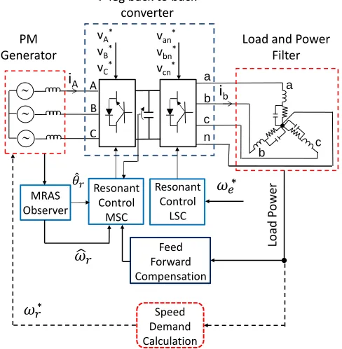
[image:1.612.314.558.476.725.2]In this paper the application of a 7-leg back-to-back voltage source PWM converter is proposed with a 3-leg Machine-Side Converter (MSC) and a 4-leg Load-Side Converter (LSC) as shown in Fig. 1. Both converters are controlled using space vector modulation algorithms and RCs. RCs have been selected in this application because they have several advantages in 4-wire applications. For example they provide the capability to control zero sequence currents and voltages [5]–[7] (which do not exist in signals obtained by conventional - and d-q transformations) and they also allow straightforward implementation of power factor control at the generator side (as discussed in Section IIIA). Additionally, RCs provide a simple approach to eliminate waveform distortion using cascade controllers [9]–[14]. Moreover, in
Fig. 1. Proposed 7-leg variable speed generation system.
a
b c
a b
n c
i
A A BC
i
bMRAS Observer
Resonant Control
MSC
van*
vbn*
vcn*
Load and Power Filter PM
Generator
7-leg back to back converter
vA*
vB*
vC*
Resonant Control
LSC
Feed Forward Compensation
Load
Po
w
er
Speed Demand Calculation
*
* Roberto Cárdenas, IEEE Senior Member, Enrique Espina, Jon Clare, IEEE Senior Member
Patrick Wheeler, IEEE SeniorMember
Self-Tuning Resonant Control of a 7-Leg
Back-to-Back Converter for Interfacing Variable
Speed Generators to 4-Wire Loads
this paper a feed-forward compensation algorithm is proposed (see Fig. 1) which is more conveniently implemented when both sides of the 7-leg converter are controlled using resonant controllers.
In this paper the LSC output is controlled to operate at a constant 𝜔𝑒∗, corresponding to an electrical frequency of
50Hz. Therefore the resonant controllers of the LSC are tuned to operate at fixed frequencies and they have to regulate the positive, negative and zero sequence load-voltage components. When non-linear loads are fed by the LSC, waveform distortion has to be also eliminated using RCs. In the MSC side the generator output frequency varies with rotational speed. Therefore a resonant controller is proposed which has a frequency adaptive (self- tuning) structure, designed to obtain a good dynamic performance over the whole operating range.
In Fig. 1 a speed demand calculation block is required to adaptively change the speed according to some control law, e.g. to reduce the fuel consumption in a diesel-based generation system, to increase the performance of a micro-hydro system, or to improve the energy capture in a wind energy conversion system. The control system proposed in this work has been designed to operate across the whole speed range and thecalculation/regulation of the optimal rotational speed, is considered outside the scope of this paper.
The contribution of this work can be summarised as follows:
To the best of our knowledge this is the first paper where a variable speed generator is interfaced by a 7-leg back-to-back VSI to a 4-wire load. The power converter topology presented in this paper can be applied to variable speed diesel systems [15], low voltage micro-grids [16][17], [18], wind-diesel hybrid systems[19], utility power supplies [3], etc. In general this topology can be used in any application where a variable speed 3 generator has to be interfaced with a 4-wire load/grid.
A new methodology for the design of a self-tuning RC, capable of operating over a wide frequency range, is presented. The RC is designed in the z-domain, to avoid the problems related with the bilinear transform or other discretisation methods [20]. This design methodology can be advantageously used for grid connected power converters, [21], [22], droop-controlled converters for micro-grids and variable speed machines [23], [24]. The design methodology presented in this paper is certainly superior to that conventionally used to implement the “PR controller” reported in the literature [25].
A novel feed-forward compensation algorithm is analysed and presented. The feed-forward term compensates the perturbations produced by fast variations of an unbalanced linear/non-linear load on the dc-link voltage. This feed forward compensation method can be used in other applications where high dynamic response (in the presence of power oscillations produced by unbalanced signals) is required. For instance in conventional 3-leg back to back converters, [1] and even single phase systems.
Small signal models are presented, describing the dynamics of the dc-link, power balance equation, dynamics of the PMSG, etc. These small signal models consider the effect of non-linear loads and can be used to design the controllers
using conventional linear control tools. The linearised models presented in this work can be extended to other applications where power converters are used to feed non- linear unbalanced loads.
The remainder of the paper is organised as follows. Section II briefly discusses the sensorless control system; In Section III the self-tuning resonant control system is analysed; the load-side resonant control is very briefly presented in Section IV. Section V discusses the feed-forward algorithm and Section VI presents results from an experimental prototype. Finally, Section VII discusses the conclusions from the work. Parameters of the experimental rig are presented in the Appendix.
II. SENSORLESS CONTROL
Later, in Section III, it is shown that for the implementation of the self-tuning resonant controller, the rotor position (θr) and rotational speed (r) of the Permanent
Magnet Synchronous Generator (PMSG) are required. In this work θr and r are estimated using a sensorless Model
Reference Adaptive System (MRAS) observer. Such systems have been extensively discussed in the literature before [26]– [29] so only a brief discussion is provided here for completeness.
The MRAS observer is based on a reference model and an adaptive model [28], [29], [31]. The reference model is obtained as:
𝜓𝑠 = ∫(𝑣𝑠− 𝑅𝑠𝑖𝑠)𝑑𝑡 (1)
Where 𝜓𝑠 is the stator flux, 𝑣𝑠 is the stator voltage, 𝑖𝑠 is the
stator current and Rs is the stator resistance (0.2).
Unlike motors, PMSG are not expected to operate at very low rotational speeds. As stated in Section III.C it is assumed in this work that the PMSG is operating between 500rpm-2000rpm (0.25n to n). Therefore, even at 500rpm, the
voltage 𝑣𝑠 is relatively large compared to the small voltage
drop variations produced by changes in Rs with temperature
(see (11)).
For instance if the PMSG winding temperature varies from 20C to the maximum value of 140C, the stator resistance will change from Rs0.2 to a Rs0.294 (assuming a temperature coefficient =0.00393/C for the copper windings). Therefore the resistive voltage drop will change from 3V to 4.4V at rated current (i.e. V1.4V). Hence even for the extreme case of rated current, minimum speed and the maximum allowable temperature rise, the change in resistive voltage drop is less than 5% of the phase voltage. Moreover, as reported in [31], for permanent magnet machines the stability of MRAS-based sensorless control loops is not compromised by stator resistance variation.
The adaptive model is obtained using:
𝜓̂𝑠 = 𝐿𝑠𝑖𝑠+ 𝜓𝑚𝑒𝑗𝜃̂𝑟 (2)
Where the superscript ““ indicates an estimated variable. In (2) Ls is the stator inductance and 𝜓𝑚= 𝜓𝑚𝑒𝑗𝜃̂𝑟 is the
estimated rotor flux. A smooth air-gap permanent magnet machine is used in this work (i.e. Ld=Lq=Ls).
model and that obtained from (1) is defined as:
𝜀 = |𝜓𝑠⊗ 𝜓̂𝑠| = |𝜓𝑠𝛽𝜓̂𝑠𝛼− 𝜓𝑠𝛼𝜓̂𝑠𝛽| = | 𝜓𝑠| |𝜓̂𝑠| sin (𝜃) (3)
In (3) the symbol represents cross-product and is the phase angle between the vectors 𝜓𝑠 and 𝜓̂𝑠. The advantages
of using cross product for the calculation of 𝜀 are discussed in [32].
Unlike induction machines, in a PMSG there is no slip velocity (i.e. slip=0) and the rotational speed is equal to the
stator electrical frequency. Therefore the speed can be correctly estimated from the frequency of the electrical signals, even if the stator resistance is affected by temperature variations. This is also concluded by inspecting (2)-(3) and a rigorous mathematic demonstration is presented in [31]. However because the error 𝜀 is defined as the cross product between 𝜓𝑠 and 𝜓̂𝑠 (see (3)), the rotor position angle 𝜃̂𝑟 can
be incorrectly estimated if the phase angle of the stator flux 𝜓𝑠
(obtained from (1)) is affected by large stator resistance variations. Nevertheless, as discussed before, for the speed operating range the variation in the stator resistance voltage drop, due to temperature effects, is relatively small compared with the PMSG internal voltage (see Fig. 2a). Moreover, in this work the generating system is designed to operate with a power factor close to unity. Hence, the position error in 𝜓𝑠 is
further reduced considering that 𝑣𝑠 and −𝑅𝑠𝑖𝑠 (see (1)) have
almost identical phase. This is depicted in Fig. 2a, where the calculation of the vectors 𝑣𝑠− 𝑅𝑠𝑖𝑠 and 𝑣𝑠− (𝑅𝑠+ ∆𝑅𝑠)𝑖𝑠 is
shown. If the angle 0 (corresponding to close to unity power factor operation of the PMSG), then the phase shift between both vectors is also zero. Notice that Fig. 2a is not drawn to scale and the voltage drops 𝑅𝑠𝑖𝑠 and 𝛥𝑅𝑠𝑖𝑠 have been
Fig. 2. a) Phasor diagram showing the calculation of the vectors 𝑣𝑠− 𝑅𝑠𝑖𝑠
and 𝑣𝑠− (𝑅𝑠+ ∆𝑅𝑠)𝑖𝑠 b) Proposed MRAS observer.
magnified in that figure.
If the PMSG is utilised at an operating point where the effect of the stator resistance variation is no longer negligible, then the implementation of on-line identification methods could be required. For instance the PMSG parameter identification method reported in [16] based on adaptive observers, or the sliding-mode observer proposed in [33]. Alternatively some of the methods proposed for stator resistance identification in induction machines, e.g. the P-based MRAS observer reported in [34] could be modified for Rs identification in PMSGs.
The MRAS observer used in this work is shown in Fig. 2b. To avoid the drift produced by integrating dc signals, the reference stator flux 𝜓𝑠 is calculated using a band-pass filter
instead of a pure integrator. The cross-product is calculated using the -β components of (1)-(2). In Fig. 2b a PI controller is used to drive the error of (3) to zero, by adjusting the position of the magnetic flux 𝜓𝑚.
In most of the applications related to variable speed generation of electrical energy (e.g. wind energy systems, diesel generation, etc.) the changes in rotational speed are relatively slow, due to the inertia of the prime-mover. Therefore to design the PI controller of Fig. 2b, a simplified small-signal model can be used, similar to that discussed in [26].
Using the parameters of the PMSG and experimental rig (see the appendix), the MRAS has been designed for a bandwidth of about 20Hz.
III. SELF-TUNING RESONANT CONTROL OF THE MACHINE-SIDE CONVERTER
A. Proposed Control System for the MSC.
The position angle 𝜃̂𝑟 is estimated from the MRAS
observer of Fig. 2. Because 𝜃̂𝑟 corresponds to the flux vector
𝜓𝑚 angle, (see Fig. 3), the position of the PMSG machine
internal voltage 𝜃̂𝑀 is estimated as:
𝜃̂𝑀 = 𝜃̂𝑟+𝜋2 (4)
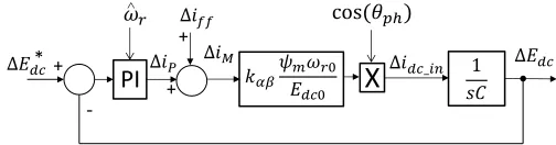
Figure 3 shows the proposed control system for the MSC. A PI controller, whose output is the current iP, regulates the
dc-link voltage of the back-to-back converter. An additional term from a feed-forward compensation algorithm (see iff in Fig. 3)
can be used to improve the dynamic performance of the dc-link voltage. This is further discussed in Section V.
In order to operate the generator with unity displacement factor, the reference currents required are:
𝑖𝛼∗ = 𝑖𝑀cos(𝜃̂𝑀)
𝑖𝛽∗ = 𝑖𝑀 sin (𝜃̂𝑀) (5)
It is also possible to introduce a phase shift angle 𝜃𝑝ℎ between the voltage and stator current of the PMSG. For instance three alternatives to obtain 𝜃𝑝ℎ have been presented in the literature
[27], [35] (see the phasor diagram of Fig. 4). Option 1 operates the PMSG at unity power factor, maximising the power transfer from the PMSG to the load [27], with the MSC providing the reactive power required by the inductance Ls.
Option 3 operates the MSC at unity power factor with the
[image:3.612.52.296.436.716.2]Fig. 3. Generator-side control system.
Fig. 4. Phasor diagram corresponding to the input stage.
required phase angle 𝜃𝑝ℎ calculated by setting 𝑣𝑀 ≈ 𝜔𝑟𝜓𝑚
yielding:
𝜃𝑝ℎ≈ −𝑠𝑖𝑛−1(𝜓𝐿𝑠
𝑚 |𝑖𝑀|) (6) Option 2 attempts to reduce saturation and obtain a compromise between the converter rating and the generator rating [35], by locating the current mid-way between the voltage vectors 𝑣𝑀 and 𝑣𝑐 with 𝜃𝑝ℎ set to half the value of (6).
The control system proposed in this work could be used to implement any of these power factor control strategies.
B. Design of the dc-link Control System.
As discussed before, the machine stator current magnitude is controlled using a PI controller augmented by a feed-forward compensation term (see iff in Fig. 3). The design of
the PI controller is discussed below. The feed-forward algorithm is discussed in Section V.
Neglecting the MSC losses, the power supplied by the PMSG is equal to that supplied by the MSC to the dc-link. Therefore, the following expression can be written:
𝐸𝑑𝑐𝑖𝑑𝑐_𝑖𝑛= 𝑘𝛼𝛽(𝑣𝑀𝛼𝑖𝑀𝛼+ 𝑣𝑀𝛽𝑖𝑀𝛽) (7)
Where 𝑖𝑑𝑐_𝑖𝑛 is the dc current on the generator side and 𝑘𝛼𝛽 is dependent on the - transformation being used. Using the angle 𝜃𝑝ℎ, then (7) can be written as:
𝐸𝑑𝑐𝑖𝑑𝑐_𝑖𝑛= 𝑘𝛼𝛽 𝑖𝑀 𝑣𝑀cos (𝜃𝑝ℎ) (8)
where vM and iM are the magnitude of the generator voltage
and current vector respectively. For a PMSG 𝑣𝑀 ≈ 𝜓𝑚𝜔𝑟. Therefore, the dc link current 𝑖𝑑𝑐_𝑖𝑛 is obtained as:
𝑖𝑑𝑐_𝑖𝑛= 𝑘𝛼𝛽𝜔𝐸𝑟𝜓𝑚
𝑑𝑐 𝑖𝑀 cos (𝜃𝑝ℎ) (9)
Linearising the system about an operating point indicated by the subscript “0” yields:
∆𝑖𝑑𝑐𝑖𝑛= 𝑘𝛼𝛽𝜓𝑚cos (𝜃𝑝ℎ) [𝐸𝜔𝑟0
𝑑𝑐0∆𝑖𝑀+
𝑖𝑀0
𝐸𝑑𝑐0∆𝜔𝑟−
𝜔𝑟0𝑖𝑀0
𝐸𝑑𝑐02 ∆𝐸𝑑𝑐] (10)
As discussed before, in this work it is assumed that the PMSG speed changes slowly, therefore the term ∆𝜔𝑟 can be
neglected when the dynamics of the current iM are considered.
Moreover the variation idc_in produced by Edc(last term in
(10)), is compensated by an identical variation in idc_out at the
LSC side. This is due to the fact that the LSC is operating with constant power output and the load voltage is regulated with a fast dynamic response. Therefore neglecting ∆𝜔𝑟, Δ𝐸𝑑𝑐 the
current ∆𝑖𝑑𝑐 circulating through the dc link capacitors is
obtained as:
Δ𝑖𝑑𝑐= 𝑘𝛼𝛽cos (𝜃𝑝ℎ)𝜔𝐸𝑟𝑜𝜓𝑚
𝑑𝑐𝑜 Δ𝑖𝑀 (11) The transfer function of (11) and the small signal model of Fig. 5 can be used for the design of the dc-link PI controller. Notice that the gain of the controller is a function of r. This
allows the system to remain tuned in spite of speed variations (see (11)). Moreover, even if the relatively small losses of the system (not considered in (7)) affect the gain of (11), linear control tools can be used to design a robust PI controller whose performance is little affected by small variations of this gain.
Notice that in (9-11) it is assumed that the feed-forward current (∆𝑖𝑓𝑓) is an external perturbation. Therefore it can be
considered that ∆𝑖𝑃= ∆𝑖𝑀 because the closed loop poles of
the dc link voltage control system are not affected by the feed-forward compensation algorithm.
C. Generator-Side Resonant Control System.
Resonant Controllers are based on the internal model principle and they can be used in control systems with sinusoidal reference signals [5]–[7], [9], [10], [25], [36]–[38]. One of the advantages is that a single RC per phase can be used to regulate the positive, negative and zero sequence signals at the load-side converter. In this application RCs are used to regulate the stator current in the PMSG and the voltage of the load fed by the LSC.
[image:4.612.310.562.657.723.2]Resonant controllers have been discussed in the literature however RCs are generally used in applications where variations in the resonant frequency are small, e.g for grid-connected converters [10], [25], [36]. However, in the proposed system, the PMSG can operate over a wide speed range (e.g. 500rpm to 2000rpm). Therefore, the coefficients of the resonant control system have to be adjusted according to the stator frequency variation, in order to operate with a suitable bandwidth and phase margin over the whole speed
Fig. 5. Control system for the regulation of the dc-link voltage.
3/2
X
X
i
*i
β*+
+
i
-i
ai
b2/3
v
*v
β*- RC
+
+
PI
E
dc*
-E
dci
Pi
βi
ffGenerator
i
Mv
Mv
ci
M1
2
3
rL
si
MPI
X
+
-*
range. This type of controller is usually called a “self-tuning” resonant controller in the literature [23], [24], [39], [40]. To the best of our knowledge, [39] is the only paper where a self-tuning RC is designed and experimentally tested for a system where operation over a wide frequency range is considered. However, in contrast to the approach proposed here, the methodology reported in [39] proposes to locate the resonant poles in a position where the PMSG stator currents cannot be regulated with low or zero steady state error. In this paper, digital design in the z-plane is proposed, avoiding the problems associated with the conventional implementation of resonant controllers based on discretisation methods [20].
The stator current of the PMSG is obtained from:
𝑣𝑀 = 𝑅𝑠𝑖𝑀+ 𝐿𝑠𝑑𝑖𝑑𝑡𝑀+ 𝑣𝑐 (12)
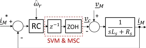
where 𝑣𝑐 is the MSC voltage vector. Using (11)-(12) the control loop shown in Fig. 6 is proposed where the reference current vector ( 𝑖𝑀∗) is derived from (5). The MSC voltage vector 𝑣𝑐 is obtained at the output of a self-tuning resonant
controller (block labelled “RC” in Fig. 6) whose transfer function is:
𝑅𝐶(𝑧) = 𝐾
𝑟(𝑧−𝑟(𝜔̂𝑟)𝑒𝑗𝜔̂ 𝑟𝑇𝑠)(𝑧−𝑟(𝜔̂𝑟)𝑒−𝑗𝜔̂ 𝑟𝑇𝑠)(𝑧−𝑒𝑗𝜔̂ 𝑟𝑇𝑠)(𝑧−𝑒−𝑗𝜔̂ 𝑟𝑇𝑠) (13)
Notice that in (13), ω̂r is the rotational speed (in electrical rad/s) estimated by the MRAS observer. As demonstrated in [31], tracking of the rotational speed by an MRAS observer in a PMSG is not affected by inaccurate identification of the machine parameters, i.e. Rs, Ls , therefore if the rotational
speed changes relatively slowly, the resonant controller of (13) is tuned to the correct frequency even if the machine parameters change. In Fig. 6 the SVM and MSC is represented as a zero order hold (see block labelled “ZOH”) and a delay of one sampling period.
The controller of (13) has two poles located in the unit circle (see Fig. 7) and two zeroes, relatively closed to the poles, used to increase the damping coefficient of the closed loop system. In (13), Ts is the sampling time, Kr is the controller gain and
𝑟(𝜔̂𝑟) is the distance from the controller zeros to the origin.
For variable speed operation of the PMSG, the poles of (13) are moved along the unit circle in order to track, with zero steady-state error, the reference currents of (5) (see Δ𝜔̂𝑟 in Fig. 7).
In this work the values of Kr and 𝑟(𝜔̂𝑟) have been tuned
[image:5.612.311.562.49.330.2]using Bode diagrams and Evan’s root locus at different operating points. For instance in Fig. 8 the open loop Bode diagram, considering operation of the PMSG at 2000rpm, is shown. The control system has been designed to obtain a phase margin of 60 at this operating point with a current control system bandwidth of 60-65Hz.
Fig. 6. Resonant control system for the generator side converter.
Fig. 7. Poles and zeroes of the resonant controller.
Fig. 8. Open loop bode diagram for operation at 2000rpm.
From the analytical and experimental work, and considering the parameters of the experimental system presented in the appendix, it has been concluded that for most of the operating range an almost fixed value of 𝑟(𝜔̂𝑟) ≈ 0.95 produces a good
dynamic response. However for a relatively low speed (close to 500rpm), the plant pole is closer to the poles and zeroes of the RC (see Fig. 7) and the value of 𝑟(𝜔̂𝑟) has to be changed
in order to maintain a good dynamic performance. This approach is simple to implement and produces a good result considering that the PMSG acceleration is relatively slow. A small look-up table or similar implementation methodology can be used to obtain the value of 𝑟(𝜔̂𝑟).
Expanding (13), the z-plane transfer function is obtained as:
𝑅𝐶(𝑧) = 𝐾
𝑟(𝑧2−2𝑟(𝜔̂𝑟)𝑐𝑜𝑠(𝜔̂𝑟𝑇𝑠)𝑧+𝑟(𝜔̂𝑟)2)(𝑧2−2𝑐𝑜𝑠(𝜔̂𝑟𝑇𝑠)𝑧+1) (14) Using (14) the self-tuning resonant controller can be implemented in real time using a Digital Signal Processor (DSP).
IV. CONTROL OF THE LOAD SIDE CONVERTER
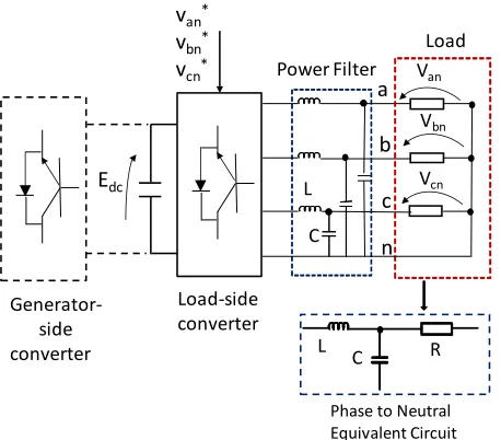
In order to feed a stand-alone load and provide a path for the circulation of zero sequence currents, the LSC has 4 legs at the output (see Fig. 9). Resonant controllers are used to regulate the load phase-to-neutral voltages (van,vbn,vcn). It is
assumed that the output frequency is constant; therefore, the LSC resonant controllers do not require frequency adaptation. The approach is essentially the same as that discussed in [5]– [7] for a 4-leg matrix converter so only a brief treatment is given here.
Assuming a resistive load, the transfer function relating the phase to neutral voltage of the load to that at the output of the LSC is:
RC
+
-*
ZOH
-+
SVM & MSC
X
o
Resonant Pole
X
o
Unit Circle
r(
r)
x
PlantPole L/R
X
o r
500rpm 2000rpm
Zero
x
SVM Delay-360 -270 -180 -90
0 40 80 120 160
Ph
a
se
(deg
)
Ma
g
n
it
u
d
e
(d
B)
100 101 102 103 104
Frequency (Hz)
Gain Peak,133Hz
2000rpm
Phase Margin (60)
r
[image:5.612.50.291.643.722.2]Fig. 9. LSC feeding an unbalanced linear/non-linear load.
𝑣𝑎𝑛(𝑠)
𝑣𝑜𝑎(𝑠)
=
𝑅𝐿𝑎
𝑠2𝑅𝐿𝑎𝐶𝑓𝐿𝑓+𝑠𝐿𝑓+𝑅𝐿𝑎 (15)
where van is the load voltage and voa is the output voltage of
the LSC; RLa is the load resistance and Cf, Lf are the
capacitance and inductance of the second order output filter respectively. A resistive load has been assumed in (15), however the control system presented in this work can be used with both leading and lagging power factor loads. Substituting RLb and RLc for RLa, transfer functions similar to (15) are
obtained for the voltages vbn and vcn in terms of vob and voc.
The resonant control system is designed for the worst case operating point, i.e. when there is no load connected to the output of the power filter, and the transfer function of (15) is:
𝑣𝑎𝑛(𝑠)
𝑣𝑜𝑎(𝑠)
=
1
𝑠2𝐶𝑓𝐿𝑓+1 (16) in this case the damping coefficient of the second order system is =0 and the poles of (16) are located on the j axis. Using (16) the control system shown in Fig. 10 is designed and implemented.
For the control system shown in Fig. 10, only one RC per phase is used. However if the output load is strongly non-linear, multiple resonant controllers could be required to supply voltages with low harmonic distortion to the load. In the experimental work discussed in this paper, the control of the LSC is realised using a single RC per phase when the 4-leg front-end converter is feeding linear loads. For loads with strong non-linear behaviour three controllers per phase are implemented for the regulation of the load voltage (see Section VI). A full discussion of the issues related to the implementation of multiple order fixed-frequency resonant controllers, is considered outside the scope of this paper and the interested reader is referred elsewhere [5], [7], [36].
V. FEED-FORWARD COMPENSATION ALGORITHM
The PMSG stator current control system is augmented with a feed-forward compensation term (see iff in Fig. 3) improving
the dynamic response of the system when fast variations in the load fed by the LSC are produced. The feed-forward algorithm is based on input/output power balancing.
Fig. 10. Resonant control system for the LSC. Only one phase is shown.
Assuming that the load voltage is well regulated and balanced, the instantaneous LSC output power is calculated as:
𝑃𝑜𝑢𝑡= 𝑅𝑒(𝑘𝛼𝛽𝑣𝐿𝑖𝑜𝑐) (17)
where the superscript “c” is the complex conjugate operator,
𝑣𝐿 is the load voltage vector (see van,vbn,vcn in Fig. 9) and 𝑖𝑜
is the LSC output current vector. Expanding (17) Pout is
obtained as:
𝑃𝑜𝑢𝑡= 𝑅𝑒[𝑘𝛼𝛽𝑣𝐿𝑒𝑗𝜔𝑒𝑡(∑ 𝑖𝑘 𝑘𝑒𝑗(𝜔𝑒𝑘𝑡+𝜃𝑘)+ ∑ 𝑖ℎ ℎ𝑒−𝑗(𝜔𝑒ℎ𝑡+𝜃ℎ))𝑐 ] (18)
which can be rewritten as:
𝑃𝑜𝑢𝑡= 𝑅𝑒[𝑘𝛼𝛽𝑣𝐿 (∑ 𝑖𝑘 𝑘𝑒𝑗((1−𝑘)𝜔𝑒𝑡+𝜃𝑘)+ ∑ 𝑖ℎ ℎ𝑒𝑗((ℎ+1)𝜔𝑒𝑡+𝜃ℎ))] (19)
With 𝑘, ℎ ≥ 1. In (18-19) the index “k” is used to denote the positive sequence LSC output currents, and “h” is used for the negative sequence components. It is assumed that (k, h) are
arbitrary phase angles.
Neglecting the losses, the power balance in the 7-leg converter can be written as:
𝑅𝑒(𝑘𝛼𝛽𝑣𝑀𝑒𝑗𝜔𝑟𝑡𝑖𝑀) = 1
2𝐶
𝑑𝐸𝑑𝑐2
𝑑𝑡 +
𝑅𝑒[𝑘𝛼𝛽𝑣𝐿 (∑ 𝑖𝑘 𝑘𝑒𝑗((1−𝑘)𝜔𝑒𝑡+𝜃𝑘)+ ∑ 𝑖ℎ ℎ𝑒𝑗((ℎ+1)𝜔𝑒𝑡+𝜃ℎ))] (20)
where the term at the left hand side of (20) is the power supplied by the PMSG and the term (1 2⁄ )𝐶(𝑑𝐸𝑑𝑐2 ⁄ )𝑑𝑡 is the instantaneous power absorbed or supplied by the dc-link capacitor bank C.
From (20) a feed-forward term can be calculated in order to improve the regulation of the dc-link voltage Edc. However, it
is relatively simple to demonstrate that the instantaneous power absorbed/supplied by the dc-link capacitance C cannot be driven to zero without producing harmonic distortion in the PMSG stator current when the LSC feeds an unbalanced non-linear load. Therefore some voltage variation has to be allowed in Edc which can be obtained using:
𝐸𝑑𝑐𝑑𝐸𝑑𝑡𝑑𝑐= −1𝐶𝑅𝑒[𝑘𝛼𝛽𝑣𝐿 (∑ 𝑖𝑘 𝑘𝑒𝑗((1−𝑘)𝜔𝑒𝑡+𝜃𝑘)+
∑ 𝑖ℎ ℎ𝑒𝑗((ℎ+1)𝜔𝑒𝑡+𝜃ℎ))] ( 𝑘 > 1) (21)
Eq. (21) can be useful for designing the dc-link capacitor bank considering the expected load characteristics.
Harmonic distortion of the stator currents are not produced when the power generated by the PMSG is balanced with the dc instantaneous power produced by the positive sequence of the fundamental load current. Therefore replacing 𝑣𝑀 ≈ 𝜓𝑚𝜔̂𝑟 a feed-forward compensation current can be obtained calculating the term |𝑖𝑀| in (20) as:
|
𝑖𝑀| = 𝑖
𝑓𝑓=
𝑃𝑎𝑣𝑔𝑘𝛼𝛽𝜓𝑚𝜔̂𝑟cos (𝜃𝑝ℎ) (22) R
C L
van*
vbn*
vcn*
Load Power Filter
Phase to Neutral Equivalent Circuit
a
b
c
n
Edc
Load-side converter
Vbn
Vcn
Van
L
C
Generator-side converter
+
Van
z-1
SVM Load side converter
ZOH
L f f f L
L
R sL L C R s
R + + 2
Plant
Resonant Controller
2 2
Van
Voa
[image:6.612.313.566.51.139.2]
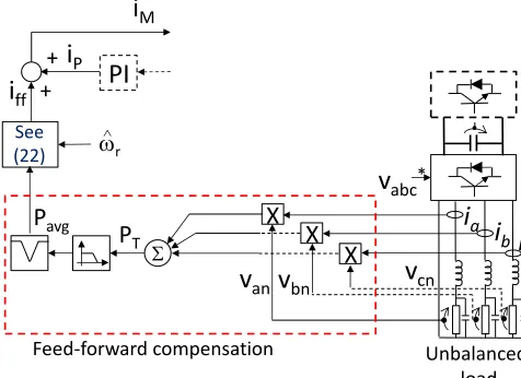
where Pavg is the dc component (i.e. obtained using k=1, ih=0 in (21)) of the load power.
The proposed feed-forward control system is shown in Fig. 11. The power Pavg is calculated using:
𝑃𝑎𝑣𝑔 = (𝑣𝑎𝑛𝑖𝑜𝑎+ 𝑣𝑏𝑛𝑖𝑜𝑏+ 𝑣𝑐𝑛𝑖𝑜𝑐) ∏ (𝑠
2+𝑚2𝜔 𝑒 2) 𝑚
∏ (𝑠𝑚 2+4𝜁𝑚𝜔𝑒𝑠+𝑚2𝜔𝑒2) (23)
The term at the right of (23) represents a cascade of notch filters tuned at 𝑚𝜔𝑒, where 𝜔𝑒 is the output frequency. If the
load is unbalanced but linear, only one notch filter is required tuned at 2𝜔𝑒. If the load is non-linear, additional notch filters
are required to eliminate the power pulsations due to the current distortion.
Fig. 11 shows the implementation of the feed-forward compensation term. The output power is calculated using measurements of the phase to neutral load voltages and LSC output currents. From these measurements the average power Pavg is calculated using (23). Because of simplicity only one
notch filter is shown in Fig. 11. An additional low-pass filter is used to eliminate the harmonics produced by the switching of the IGBT devices.
Interconnection of the control systems, discussed in the previous sections, is shown in Fig. 12.
VI. EXPERIMENTAL WORK
The control system of Fig. 12 has been experimentally implemented (see Fig. 13) using a DSP based control board and an FPGA, the latter providing the switching signals for the 14 IGBT gate drivers. Data acquisition uses 20 Analogue to Digital (ADC) channels of 14bits, 1μs conversion time each, interfaced to the DSP. Additionally two digital oscilloscopes, operating simultaneously in single shot mode (with sampling frequencies of 5MHz) have been used in some of the experimental tests to store the current and voltages of the input and output side of the 7-leg converter. Hall-effect transducers are used to measure the input currents, input voltages and output load voltages. A switching frequency of 10kHz has been used to implement the SVM algorithms.
For the experimental tests a Control Techniques, 4kW, 2000rpm, 8 pole PMSG with surface mounted magnets is used. This PMSG supplies a sinusoidal voltage waveform with a Total Harmonic Distortion (THD) of less than 1.1% (the PMSG voltage waveforms are shown in Fig 13a). The
[image:7.612.314.564.45.346.2]Fig. 11. Feed-forward compensation system.
Fig. 12. Proposed control system for the 7-leg converter.
parameters of the PMSG are given in Table I at the appendix. The prime mover is a 2 pole, 2910rpm, 5kW cage machine. A commercial inverter is used to drive the cage machine using V/F control. The machines are shown in Fig. 13c. The position encoder has not been used to implement the control strategies. A 7-leg power converter has been designed and implemented for the experimental validation of the proposed control system. The PCB is shown in Fig. 13b. Each leg has been implemented using a 1200V, 35A dual IGBT switch Infineon BSM35GB120DN2 device. The experimental system is controlled using a Texas Instruments TMS320C6713 DSP. A daughter board with an ACTEL FPGA is used to implement the PWM generation and for interfacing the A/D, D/A converters to the DSP. A 3 resistor bank with resistor taps of 10.7 and 14.7 is used for the load. An electronic relay controlled using one of the D/A output channels is used to implement the load-step variations presented in this section. Figs. 14-15 show the control system performance for an unbalanced load-step. Before the load-step the system is operating with a dc-link voltage Edc=325V, a load voltage of
115V peak, r=1650rpm and a balanced LSC output current of 5.3A (rms). At t42ms additional resistors are connected increasing the current to 12.4A (rms) in two of the phases. The output currents ia, ib and ic are shown in Fig. 14a. The neutral
current, with the presence of zero sequence components, is shown in Fig. 14b. Finally Fig. 14c shows the load voltage which has a small perturbation when the load impact is applied; this is eliminated in less than 5ms (a quarter of a cycle) by the load-side RCs.
Fig. 15 shows more experimental results corresponding to the unbalanced load step of Fig. 14. Fig. 15a shows the 3 output power. Before the unbalanced load-step, the power is
v
abc*X
X
X
v
anv
bnv
cni
ai
bi
c
P
T+
+
P
avgFeed-forward compensation Unbalanced
load
i
Pi
ffPI
See
(22) r
i
M
3/2 +
PI
X
X
i
*i
β*+
+
E
dc*
-i
-iβ
i
ai
b2/3
E
dcv
*v
β*3/2
-RC
Generator
X
X
X
v
anv
bnv
cni
ai
bi
c
P
T+ +
Generator-Side Resonant Control
P
avgPower calculation block
load
(22)
i
Pi
ff+
-V
an*V
bn*V
cn*+
+
V
oc*Load- Side Resonant Control
V
ob*MRAS Observer
[image:7.612.62.300.554.727.2]Fig. 13. a) Two line to line voltages for the PMSG operating at 2150rpm b) 7-leg converter designed and implemented in this work. c) 8-pole PMSG and 2-pole cage machine.
1.27kW without oscillations. After the load-step the mean output power is about 2kW with a relatively large 100Hz component. Using a digital notch-filter tuned at 100Hz and a first-order digital low pass filter tuned at 50Hz (see Figs. 11-12 and (23)), the feed-forward current iff is calculated by the
DSP using (22)-(23) and depicted in Fig. 15b. As discussed in Section V, this current is fed-forward to the stator current control system, to improve the dynamic response of the dc-link voltage regulation.
In Fig. 15c the dc-link voltage is shown. With feed-forward compensation, the dip is only 6V. Notice that the dc- link has a 100Hz oscillation after the unbalanced load-step is applied. As discussed in Section V the controller has not been designed to compensate the ac ripple in the dc-link voltage, to avoid distortion in the PMSG stator currents.
Notice that Fig. 15c has a different time scale. In Figs. 15a and 15b signals internally calculated by the DSP are shown. Fig. 15c shows a dc voltage signal which is captured by the digital scope.
[image:8.612.343.540.49.309.2]Fig. 16a shows the PMSG stator current corresponding to
Fig. 14. Response of the LSC control systems for an unbalanced load step in two of the phases. a) LSC output currents. b) LSC neutral current. c) Load voltages.
Fig. 15. a) 3 output power. b) feed-forward compensation current. c) dc-link voltage
the test depicted in Figs. 14-15. The input current has a frequency of about 110Hz with virtually no distortion. For this case the current is regulated with 𝜃𝑝ℎ ≈ 0 (see Fig. 3). Figs.
16b and 16c show the - tracking error of the self-tuning resonant control system. For the whole test the tracking error is low, with a peak below 0.75A produced when the current iff
has a fast variation from iff 12A to iff 18A (peak current) in
t0.5s.
The control system of Fig. 12 has been tested considering a relatively fast ramp speed variation. For this test the experimental results are shown using the effective (rms) current of each phase. This methodology is preferred because
PM Generator
Cage
Machine
Power
Filter
Encoder
MSC LSC
DC-link
c)
b)
a)
Line voltages
-15 -5 5 15
0 0.04 0.08 0.12
-150 -50
50 150
-15 -5
5 15
a)
b)
c)
Time (s)
Lo
ad
V
o
ltag
e
(v)
N
eu
tr
al
C
u
rr
en
t
(A
)
Lo
ad
C
u
rr
en
t
(A
)
Time (s)
0 0.2 0.4 0.6 0.8 1
1200 1600 2000 2400
0.4 0.45 0.5 0.55 0.6 0.65
10 14 18
0.7
a)
b)
Po
w
e
r
(W
)
C
u
rre
n
t
(A)
0 0.04 0.08 0.12
300 320
340
c)
V
o
lt
a
g
e
[image:8.612.65.284.57.455.2] [image:8.612.328.548.341.559.2]of the problems associated with displaying d-q currents under unbalanced operation. Moreover, the zero sequence components are not reflected in the d-q signals.
The LSC (rms) output currents are calculated using a digital implementation of:
𝑖𝑟𝑚𝑠= √1𝑇∫ 𝑖2(𝑡)𝑑𝑡 (24)
A low pass filter is used to calculate the root mean square value of (24).
[image:9.612.62.287.161.409.2]Fig. 16. Input currents a) Instantaneous input current. b) -axis (rms) stator current tracking error. c) -axis (rms) stator current tracking error.
Fig. 17. Control system performance for a ramp step variation. a) Reference (𝜔𝑟∗) and estimated (𝜔̂𝑟) rotational speeds. b) LSC output currents ia and ib. c)
LSC output currents ic. d) Neutral current.
Fig. 17 shows results for a speed ramp variation between r800rpm to 1500rpm. At t2s an unbalanced load step is applied to two of the phases and disconnected at t7.3s. Fig. 17a shows the estimated rotational speed 𝜔̂𝑟 and the reference
speed 𝜔𝑟∗ sent to the commercial inverter. In Figs. 17b-17c the LSC output currents ia, ib and ic are shown. Notice that the
effective current is constant in phase c and that the unbalanced load-step variations are applied to phases b and c. Finally Fig. 17d shows the zero sequence components circulating through the 4th leg, used as a neutral connection in this application. Fig. 18 shows additional signals corresponding to the ramp speed variation test shown in Fig. 17. Fig. 18a shows the magnitude of the PMSG d-q stator current. Because the system is feeding a constant load at the output, the PMSG power current is proportional to 1/r. Fig. 18b shows the
instantaneous power measured at the output. As explained before, this power is filtered and the feed-forward compensating current is obtained using (22)-(23). Fig. 18c shows the phase to neutral load voltage. Because of the boost capability of the MSC the load voltage can be regulated to a value which is higher than the internal voltage (a phase voltage of 40V at 800rpm). This is an advantage compared to previous implementations (see [5]). Notice that the load voltage is well regulated with a dip and an overshoot of less than 5V. Finally Fig 18d shows the dc-link voltage. For this test the dc-link voltage is well regulated (𝐸𝑑𝑐∗ = 300𝑉) with a dip and overshoot of less than19V (6% of Edc).
The performance of the feed-forward compensation algorithm, for the regulation of the dc-link voltage, is shown in Fig. 19. The system is operating with a rotational speed of
Fig. 18. Control system performance corresponding to the ramp step variation of Fig. 17. a) PMSG stator current. b) Instantaneous load power c) Magnitude (obtained from d-q coordinates) of the load voltage. d) dc-link voltage.
-1.5 -0.5 0.5 1.5
0 0.2 0.4 0.6 0.8 1
-1.5 -0.5 0.5 1.5
-
tra
cki
n
g
e
rro
r
(rms
A)
Time (s) b)
c)
0 0.04 0.08 0.12
-20 0 20
C
u
rre
n
t
(A)
a)
0 2 4 6
1 2 3
0 2 4 6 8 10
0 1 2 3 500 1000 1500 2000
Load step
Time (s)
Spee
d
(r
pm)
RM
S
Curr
en
t
(A)
a)
b)
c)
d)
ia, ib
ic
in
* *
400 600 800 1000 1200 5 10 15
55 65 75 85 95
C
u
rre
n
t
(A)
Po
w
e
r
(W
)
V
o
lt
a
g
e
(V)
a)
b)
c)
240 280 320 360
0 1 2 3 4 5 6 7 8 9 10
Time (s)
V
o
lt
a
g
e
[image:9.612.319.535.401.711.2] [image:9.612.62.282.442.714.2]Fig. 19. Performance of the feed-forward compensation algorithm. a) 3 balanced load step. b) dc-link voltage variation without considering feed-forward compensation. c) dc-link voltage variation considering feed-feed-forward compensation.
750rpm, the dc-link voltage is regulated to 200V and a 3 balanced load-step is applied. Fig. 19a shows the output power variation from 500W to 1250W. Fig. 19b shows the response of the dc link control system without the feed- forward term of (22). The nominal voltage is 200V and the dip and the overshoot are about 25V for a dc-link capacitor bank of about 1600F. When the feed- forward term is included (Fig. 19c) the dip and the overshoot are reduced to 15V and the settling time (considering a 2% band) is reduced from 90ms to 20ms for the same power step.
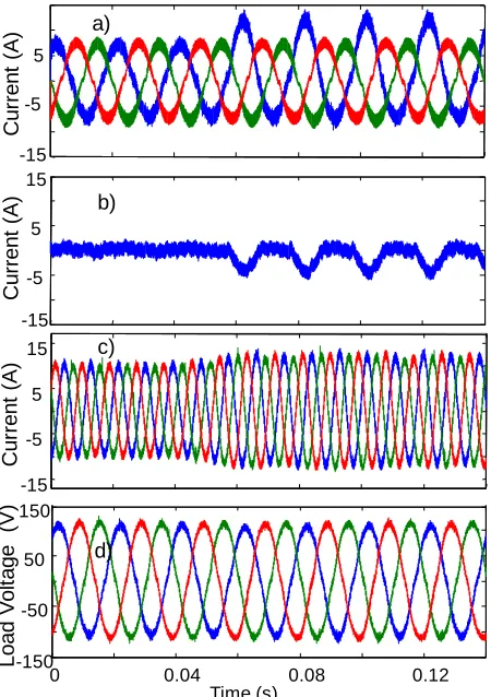
In Fig. 20 the performance of the proposed control system, for a non-linear load-step, is shown. The system is operating with a balanced load of about 1300W, 1650rpm, when at t58ms a non-linear load composed of a 14.7 resistor, in series with a rectifier diode, is applied to phase a. For this case additional resonant controllers, tuned to eliminate dc signals and third order harmonics are implemented in the LSC control system to regulate the load voltage. The implementation of high order resonant controllers is discussed in [5], [9], [36], [37].
Fig. 20a shows the LSC output currents ia, ib, ic. Before the
non-linear step, the current in phase-a has negligible distortion. After the non-linear load step the current in phase-a is increased with a noticeable dc component whose magnitude is 32% with respect to the fundamental. Moreover, after the step, the second and the fourth harmonics are also present in ia
with magnitudes of 11% and 3% respectively. Fig. 20b shows the zero sequence current components (produced by the non-linear load) that circulate in the neutral leg.
Fig. 20c shows the stator current which is well regulated with little distortion. Finally the load voltage is shown in Fig. 20d. As shown in this graphic, the load voltage is well regulated and the effects of the non-linear step are negligible. Moreover the high order resonant controller reduces the distortion in the load voltage.
Fig. 20. Control system performance considering a non-linear load step. a) LSC output currents ia, ib and ic. b) Neutral current. c) PMSG stator currents.
d) load voltage.
VII. CONCLUSIONS
A control method for a 7-leg back-to-back voltage source inverter has been presented. It is based on resonant controllers and a feed-forward compensation term. A frequency adaptive control system for the regulation of the PMSG stator current has been presented and experimentally validated. A control system topology for the regulation of the dc link voltage, avoiding distortion in the generator current, has been analysed in this work. A feed-forward compensation algorithm has been proposed that effectively improves the dynamic performance of the dc-link voltage control.
The proposed control system has been tested considering balanced, unbalanced and non-linear load operating under variable/fixed rotational speed. The results have shown the good performance achieved with the proposed control methodology.
APPENDIX
TABLE I
PARAMETER OF THE PMSG
Nominal rotational speed 2000rpm
Nominal Power 4kW
Maximum Rotational Speed 2800rpm
Torque constant 1.4Nm/A
Nominal Torque 20Nm
Voltage Constant 85.5V/Krpm
(line voltage)
Recommended Drive PWM 220/240V
500 1000 1500
170 190 210 230
0 0.2 0.4 0.6 0.8 1
170 190 210 230
Pow
er
(W)
dc
-l
ink
v
ol
tage (v
)
a)
b)
c)
Time (s)
-15 -5
5
-15 -5
5 15
0 0.04 0.08 0.12
-150 -50
50 150
-15 -5
5 15
a)
b)
c)
d)
C
u
rre
n
t
(A)
Load
V
o
lt
a
g
e
(V)
Time (s)
C
u
rre
n
t
(A)
C
u
rre
n
t
[image:10.612.315.540.47.366.2] [image:10.612.74.274.48.262.2] [image:10.612.325.540.623.739.2]Voltage (line voltage) Stator Inductance 4mH Stator Resistance 0.2 Output Waveform Sinusoidal
(THD<1.1%)
TABLE II
PARAMETER OF THE EXPERIMENTAL SYSTEM
Switching Frequency 10kHz
Output Filter Inductance Lf= 2.5mH
Output Filter Capacitance Cf= 40 μF
Output frequency 50Hz dc-link capacitance 1600F
REFERENCES
[1] R. Cardenas and R. Pena, “Sensorless vector control of induction machines for variable-speed wind energy applications,” IEEE Trans on Energy Conversion,., vol. 19, no. 1, pp. 196–205, 2004.
[2] J. Leuchter, V. Refucha, Z. Krupka, and P. Bauer, “Dynamic Behavior of Mobile Generator Set with Variable Speed and Diesel Engine,” IEEEPower Electronics Specialists Conference, 2007. PESC 2007.. pp. 2287–2293, 2007. [3] P. W. Wheeler, P. Zanchetta, J. C. Clare, L. Empringham, M. Bland, and D. Katsis, “A Utility Power Supply Based on a Four-Output Leg Matrix Converter,” IEEE Trans. Ind. Appl., vol. 44, no. 1, pp. 174–186, 2008. [4] T. Friedli, J. W. Kolar, J. Rodriguez, and P. W. Wheeler, “Comparative Evaluation of Three-Phase AC–AC Matrix Converter and Voltage DC-Link Back-to-Back Converter Systems,” IEEE Trans. Ind. Electron., vol. 59, no. 12, pp. 4487–4510, Dec. 2012.
[5] R. Cardenas, C. Juri, R. Pena, J. Clare, and P. Wheeler, “Analysis and Experimental Validation of Control Systems for Four-Leg Matrix Converter Applications,” IEEE Trans. onInd. Electron., vol. 59, no. 1, pp. 141–153, 2012.
[6] R. Cardenas, R. Peña, C. Juri, P. Wheeler, and J. Clare, “Control of a Matrix Converter For The Operation Of Autonomous Systems,” Renew. Energy, vol. 27, no. 3, pp. 1120–1129, 2012.
[7] R. Cardenas, C. Juri, R. Pena, P. Wheeler, and J. Clare, “The Application of Resonant Controllers to Four-Leg Matrix Converters Feeding Unbalanced or Nonlinear Loads,” IEEE Trans. on Power Electron., vol. 27, no. 3, pp. 1120–1129, 2012.
[8] S. Ei-Barbari and W. Hofmann, “Digital control of a four leg inverter for standalone photovoltaic systems with unbalanced load,” IEEE Ind. Electron. Soc. IECON 2000.26th Annu. Conf., no. 2, pp. 729–734, 2000.
[9] M. Rashed, C. Klumpner, and G. Asher, “Repetitive and Resonant Control for a Single-Phase Grid-Connected Hybrid Cascaded Multilevel Converter,”
IEEE Trans. on Power Electronics, , vol. 28, no. 5. pp. 2224–2234, 2013. [10] M. Angulo, D. A. Ruiz-Caballero, J. Lago, M. L. Heldwein, and S. A. Mussa, “Active Power Filter Control Strategy With Implicit Closed-Loop Current Control and Resonant Controller,” IEEE Trans. on Industrial Electronics, vol. 60, no. 7. pp. 2721–2730, 2013.
[11] Y. Yang, K. Zhou, and M. Cheng, “Phase Compensation Resonant Controller for PWM Converters,” IEEE Trans. onInd. Informatics, , vol. 9, no. 2. pp. 957–964, 2013.
[12] K. Zhou, Y. Yang, F. Blaabjerg, and D. Wang, “Optimal Selective Harmonic Control for Power Harmonics Mitigation,” IEEE Trans on Ind. Electronics, , vol. 62, no. 2. pp. 1220–1230, 2015.
[13] W.-L. Chen and J.-S. Lin, “One-Dimensional Optimization for Proportional Resonant Controller Design Against the Change in Source Impedance and Solar Irradiation in PV Systems,” IEEE Trans. on,Industrial Electronics, vol. 61, no. 4. pp. 1845–1854, 2014.
[14] T. Dragicevic, J. M. Guerrero, and J. C. Vasquez, “A Distributed Control Strategy for Coordination of an Autonomous LVDC Microgrid Based on Power-Line Signaling,” IEEE Trans. onInd. Electronics, vol. 61, no. 7. pp. 3313–3326, 2014.
[15] R. Pena, R. Cardenas, J. Proboste, J. Clare, and G. Asher, “Wind-Diesel Generation Using Doubly Fed Induction Machines,” IEEE Trans. onEnergy Conversion, vol. 23, no. 1, pp. 202–214, 2008.
[16] M. A. Hamida, S. Member, J. De Leon, A. Glumineau, and R. Boisliveau, “An Adaptive Interconnected Observer for Sensorless Control of PM Synchronous Motors With Online Parameter Identification,” IEEE Trans. Ind. Electron., vol. 60, no. 2, pp. 739–748, 2013.
[17] F. Tang, X. Zhou, L. Meng, J. M. Guerrero, and J. C. Vasquez, “Secondary voltage unbalance compensation for three-phase four-wire islanded microgrids,” Multi-Conference on Systems, Signals & Devices (SSD), 2014 11th International. pp. 1–5, 2014.
[18] F. Rojas-Lobos, R. Kennel, and R. Cardenas-Dobson, “3D-SVM algorithm and capacitor voltage balancing in a 4-leg NPC converter operating under unbalanced and non-linear loads,” Power Electronics and Applications (EPE), 2013 15th European Conference on. pp. 1–10, 2013.
[19] J. Leuchter, V. Rerucha, Z. Krupka, and P. Bauer, “Dynamic Behavior of Mobile Generator Set with Variable Speed and Diesel Engine,” 2007 IEEE Power Electron. Spec. Conf., pp. 2287–2293, 2007.
[20] A. G. Yepes, F. D. Freijedo, J. Doval-Gandoy, O. López, J. Malvar, and P. Fernandez-Comesaña, “Effects of Discretization Methods on the Performance of Resonant Controllers,” IEEE Trans. on Power Electron., vol. 25, no. 7, pp. 1692–1712, 2010.
[21] F. Gonzalez-Espin, I. Patrao, E. Figueres, and G. Garcera, “An Adaptive Digital Control Technique for Improved Performance of Grid Connected Inverters,” IEEE Trans. on Ind. Informatics, , vol. 9, no. 2. pp. 708–718, 2013.
[22] X. Guillaud, P. Degobert, and R. Teodorescu, “Use of resonant controller for grid-connected converters in case of large frequency fluctuations,” 2007 Eur. Conf. Power Electron. Appl., no. 1, pp. 1–8, 2007. [23] P. Degobert, G. Remy, J. Zeng, P.-J. Barre, and J.-P. Hautier, “High performance control of the permanent magnet synchronous motor using self-tuning resonant controllers,” System Theory, 2006. SSST ’06. Proceeding of the Thirty-Eighth Southeastern Symposium on. pp. 382–386, 2006.
[24] P. Degobert, C. Remy, P.-J. Barre, and J.-P. Hautier, “High Performance Control of the Permanent Magnet Synchronous Motor Using Self-Tuning Resonant Controllers,” 2006 Proceeding Thrity-Eighth Southeast. Symp. Syst. Theory, no. 1, pp. 300–304, 2006.
[25] C. Xia, Z. Wang, T. Shi, and X. He, “An Improved Control Strategy of Triple Line-Voltage Cascaded Voltage Source Converter Based on Proportional-Resonant Controller,” IEEE Trans. onInd. Electronics, vol. 60, no. 7. pp. 2894–2908, 2013.
[26] R. Cardenas, R. Pena, J. Clare, G. Asher, and J. Proboste, “MRAS Observers for Sensorless Control of Doubly-Fed Induction Generators,” IEEE Trans. on Power Electron., vol. 23, no. 3, pp. 1075–1084, May 2008. [27] T. Halkosaari, “Speed Sensorless Vector Control of a Redundant Permanent Magnet Wind Power Generator,” IEEE Int. Symp. Ind. Electron., pp. 2595–2600, Jun. 2007.
[28] D. Xiao and M. F. Rahman, “Sensorless Direct Torque and Flux Controlled IPM Synchronous Machine Fed by Matrix Converter Over a Wide Speed Range,” IEEE Trans. onInd. Informatics, vol. 9, no. 4. pp. 1855–1867, 2013.
[29] F. Wang, Z. Chen, P. Stolze, J. Stumper, J. Rodriguez, and R. Kennel, “Encoderless Finite-State Predictive Torque Control for Induction Machine With a Compensated MRAS,” IEEE Trans. on Ind. Informatics, vol. PP, no. 99. p. 1, 2013.
[30] R. Peña, R. Cardenas, J. Proboste, G. Asher, and J. Clare, “Sensorless Control of Doubly-Fed Induction Generators Using a Rotor-Current-Based MRAS Observer,” IEEE Trans. on Ind. Electron., vol. 55, no. 1, pp. 330–339, 2008.
[31] P. S. and S. S., “Stability and Dynamic Performance Improvement of Adaptive Full-Order Observers for Sensorless PMSM Drive,” IEEE Trans. on Power Electron., vol. 27, no. 2, pp. 588–600, 2012.
[32] C. Schauder, “Adaptive speed identification for vector control of induction motors without rotational transducers,” IEEE Trans. on Ind. Appl, vol. 28, no. 5, pp. 1054–1061, 1992.
[33] L. Zhao, J. Huang, H. Liu, B. Li, and W. Kong, “Second-Order Sliding-Mode Observer With Online Parameter Identification for Sensorless Induction Motor Drives,” IEEE Trans. on Ind. Electron., vol. 61, no. 10, pp. 5280–5289, Oct. 2014.
[34] S. Basak, a. V. Ravi Teja, C. Chakraborty, and Y. Hori, “A new model reference adaptive formulation to estimate stator resistance in field oriented induction motor drive,” IECON 2013 - 39th Annu. Conf. IEEE Ind. Electron. Soc., pp. 8470–8475, Nov. 2013.
[35] H. Polinder, F. F. A. van der Pijl, G.-J. de Vilder, and P. J. Tavner, “Comparison of direct-drive and geared generator concepts for wind turbines,” IEEE Trans. on Energy Conversion, vol. 21, no. 3. pp. 725–733, 2006.
[37] M. Castilla, J. Miret, A. Camacho, J. Matas, and L. G. de Vicuna, “Reduction of Current Harmonic Distortion in Three-Phase Grid-Connected Photovoltaic Inverters via Resonant Current Control,” IEEE Trans. on Ind. Electronics, vol. 60, no. 4. pp. 1464–1472, 2013.
[38] C. Xia, F. Zhou, Z. Wang, and X. He, “Equivalent Switch Circuit Model and Proportional Resonant Control for Triple Line-Voltage Cascaded Voltage-Source Converter,” IEEE Trans. onPower Electronics, vol. 28, no. 5. pp. 2389–2401, 2013.
[39] J. Zeng, P. Degobert, D. Loriol, and J.-P. Hautier, “Robust design of the self-tuning resonant controller for AC current control systems,” IEEE International Conference onIndustrial Technology, 2005.. pp. 783–788, 2005. [40] A. R. Al-Ali, G. R. Kenny, and A. B. Bonds, “Self tuning resonant circuit using a microprocessor based system,” IEEE Proceedings of Southeastcon ’91, pp. 138–141 vol.1, 1991.
Roberto Cárdenas (S’ 95-M’97-SM’07) was born in Punta Arenas Chile. He received his B.S. degree from the University of Magallanes, Chile, in 1988 and his Msc. and Ph.D degrees from the University of Nottingham in 1992 and 1996 respectively. From 1989-1991 and 1996-2008 he was a lecturer in the University of Magallanes Chile. From 1991 to 1996 he was with the Power Electronics Machines and Control Group (PEMC group), University of Nottingham, United Kingdom. From 2009-2011 he was with the Electrical Engineering Department, University of Santiago. He is currently a professor in power electronics and drives with the Electrical Engineering Department, University of Chile, Chile. He received the Best Paper Award from the IEEE TRANSACTIONS ON INDUSTRIAL ELECTRONICS in 2005. His main interests are in control of electrical machines, variable speed drives and renewable energy systems. Professor Cárdenas is a senior member of the Institute of Electrical and Electronic Engineers.
Enrique Espina was born in Santiago, Chile, in 1986. He received the B.Sc. degree in electrical engineer from the University of Santiago of Chile, Santiago, Chile, in 2012. He is currently a M.Sc. student at the Electrical Engineering Department, University of Chile, Santiago, Chile. His research interests include renewable generation systems, distributed generation, micro-grids and power electronics converters.
Jon Clare (M’90, SM'04) was born in Bristol, England. He received his BSc and PhD degrees in Electrical Engineering from The University of Bristol, UK. From 1984 to 1990 he worked as a Research Assistant and Lecturer at The University of Bristol involved in teaching and research in power electronic systems. Since 1990 he has been with the Power Electronics, Machines and Control Group at the University of Nottingham, UK and is currently Professor in Power Electronics. His research interests are: power electronic converters and modulation strategies, variable speed drive systems and electromagnetic compatibility. Professor Clare is a Member of the Institution of Engineering Technology and a Senior Member of the Institute of Electrical and Electronic Engineers.