© 2019, IRJET | Impact Factor value: 7.211 | ISO 9001:2008 Certified Journal
| Page 3082
DESIGN AND ANALYSIS OF INDUSTRIAL IMPELLER USING
OPTIMIZATION TECHNIQUE
N.Mohanrajhu
1, Vignesh P
2, Padmanaban E
2, Pradeep Raj T
21
Assistant Professor, Department Mechanical Engineering,
R.M.K. Engineering College, Kavaraipettai-601206, Tamilnadu,India, [email protected]
2
U.G.Student, Department Mechanical Engineering,
R.M.K. Engineering College, Kavaraipettai-601206, Tamilnadu, India
Abstract
-Centrifugal pumps are widely used in steam power plants, sewage, hydraulic power service, food processing factories and mines, because of their suitability in practically any service. The aim is to determine and check the stress characteristics of the impeller using optimized analytical techniques. The static structural of the impeller with tapered blades was built using CATIA. The convergence properties of the Finite Element (FE) model was then verified by mesh refinement and mass distribution methods. Next, a pre-test plan was performed before conducting a modal test in order to select the material on the impeller. This work focuses on the optimization of process parameters for Impeller in Taguchi technique to obtain maximum stress. The Experiments were performed with different three process parameter and three level such as impeller material (cast iron-CI, Aluminium-AL, Stainless steel-SS), blade angle (30,º45º,60º) and Number of blade (4,5,6) . Analysis of variance (ANOVA) was employed to determine the most significant control factors affecting the output power. The Results shows that the Taguchi method was successful in the optimization of Impeller process parameters for better output power.KeyWords: TDH-Total dynamic height, Optimization, Tauguchi, Impeller.
1. INTRODUCTION
1.1 Principle of the centrifugal pump
The centrifugal pump creates an increase in pressure by transferring mechanical energy from the motor to the fluid through the rotating impeller. The fluid flows from the inlet to the impeller centre and out along its blades. The centrifugal force hereby increases the fluid velocity and consequently also the kinetic energy is transformed to pressure.
1.2 BASIC COMPONENTS
Volute, casing, body or Diffuser Impeller or impellers
Driver (motor)
1.2.1 Casing
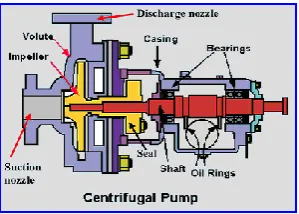
[image:1.595.363.513.383.490.2]The pump’s casing houses the whole assembly and protects it from harm as well as forces the fluid to discharge from the pump and convert into pressure. The casings design does not influence TDH but is important to reduce friction losses. It supports the shaft bearings and takes the centrifugal forces of the rotating impeller and axial loads caused by pressure thrust imbalance.
Figure 1: Basic components
1.2.1 Pump Impeller
The impeller is the essential part of a centrifugal pump. Its performance depends on the impeller diameters and its design. The pump’s TDH is basically defined by the impeller’s inner and outer diameter and the pump’s capacity is defined by the width of the impeller vanes. In general, there are three possible types of impellers, open, enclosed and semi open impellers, each suitable for a specific application. Impellers are made of cast iron or carbon steel, while impeller for aggressive fluids and slurries to require high end materials to ensure a long pump.
2. OBJECTIVE
• To modified the industrial radial flow impeller • To identified the impeller geometrical
parameter
© 2019, IRJET | Impact Factor value: 7.211 | ISO 9001:2008 Certified Journal
| Page 3083
• To identified the optimum results
• To fabricate the optimum result impeller and find the efficiency
3.
OPTIMIZATION OF DESIGN
The practice in industry to improve the performance of a pump is to redesign it based on the feedback gained from field experience. Though this method is reliable, it is tedious and time consuming. The optimization techniques are helpful to overcome the difficulty.
3.1 Impeller Design
Do -The diameter of the impeller eye is
dependent on the shaft diameter, Ds, which must initially
approximated. The hub diameter, DH, is made 5/16 to ½
inch larger than Ds. After calculating Ds and DH, DO is
based on the known flow rate. The inlet vane edge diameter, D1, made equal to DO in order to ensure
smooth flow.
Required head: hv = 150 ft
Required flow rate: Q=2000 gpm Required speed: N = 2820 rpm
Dynamic Pressure Head:-
Applying Bernoulli principle: The first force cause the absolute velocity of the object as circumferential speed which means Dynamic Pressure Head. The equation of Dynamic pressure Head is,
Hd= /2g = 14.26 m
Static Pressure Head:-
The second force creates the static pressure. If a mass moves radially outward along a vane of the impeller its orbit will be a spiral-shaped curve. We can easily calculate its angular speed. In two dimensions the angular velocity ω is given by
ω =2π*2960/60 =309.37 rpm
So during it movement the centrifugal force Fc always
present as
Fc=mrw2=1132.3N
The centrifugal acceleration increase linearity on the radius R (variable). In constant gravitational acceleration g, static pressure of a column of water h is
Hs = gh = 96.76 m
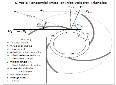
[image:2.595.339.533.171.313.2]Velocity diagram and work done by impeller:-The velocity diagram and work done by impeller of centrifugal pump on the liquid may be derived same way as for a turbine, since radial flow centrifugal pump acts as a reversed of an inward radial flow reaction turbine
Figure 2 : Simple Tangential Impeller Velocity Triangles
The following assumption made for analysis: Liquid makes radial inlet at the impeller.
No energy losses in impeller in impeller due to friction and eddy formation.
Liquid enters without shock.
Velocity distribution to be uniform in the narrow passages formed between two adjacent vanes.
3.2 Calculations for the Impeller
. The stresses encountered to centrifugal force and fluid pressure are relatively low; otherwise, they need to be taken into account.
• Impeller inner Dia, D = 114mm • Impeller angle at Dia, D2 = 38mm • Vane angle at outlet = 25 • Torque, T = 3.896Nm
STANDARD FOR IMPELLER:
CAST IRON, 5 BLADE, 30 deg inlet angle
© 2019, IRJET | Impact Factor value: 7.211 | ISO 9001:2008 Certified Journal
| Page 3084
4. VIBRATIONS
4.1 Vibrations of Centrifugal Pump
The basic principal of operation for a centrifugal pump is that a shaft mounted rotating impeller inside a housing (volute) imparts energy to the fluid being moved.
4.2 SUMMARY OF COMMON PUMP VIBRATION
PROBLEMS (Detected Using Vibration Analysis)
4.2.1 Cavitation
Cavitation typically generates random, higher energy, which is superimposed with blade frequency harmonics (multiples). Cavitation results when absolute pressure of the liquid at the pump impeller inlet approaches the vapor pressure of or “gravel” are passing through the pump.
4.2.2 Pump Flow Pulsation
Pump flow pulsation is a condition that develops when a pump is operating near its shut-off head. However, these peaks will not be stable, increasing and decreasing as the flow pulsation occurs. Pressure gauges on the discharge piping will fluctuate up and down. If the pump has a discharge swing check valve, the valve arm and counter-weight will bounce back and forth indicating unstable flow.
4.2.3 Bent Pump Shaft
Bent shaft cause axial vibration with axial phase differences tending towards 180° on the same rotor. Dominant vibration normally occurs at 1X RPM if bent near shaft center, but at 2X RPM if bent near the coupling.
4.2.4 Unbalance of Pump Impeller
Pump Impellers should be precision balanced at the pump original equipment manufacturer(OEM). This is particularly important since forces due to unbalance greatly affect life of the pump bearings(bearings life varies inversely with the cube of imposed dynamic load).
4.2.5 Shaft Misalignment
Shaft misalignment is a condition found on direct drive pumps where the centerlines of two coupled shafts are not coincident. Parallel misalignment is a condition where the shaft centerlines are parallel but offset from one another. The vibration spectrum often will show 2X higher than 1X and 3X higher than normal with 180° out of phase across the coupling.
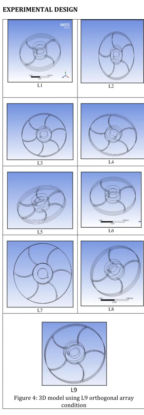
5. EXPERIMENTAL DESIGN
L1 L2
L3 L4
L5 L6
L7 L8
[image:3.595.330.563.92.761.2]
L9
© 2019, IRJET | Impact Factor value: 7.211 | ISO 9001:2008 Certified Journal
| Page 3085
5.1 Design of Experiments
Design of experiments (DOE) is a structured method that is used to identify relationships between several input variables and output responses. Using DOE, the resources needed to run the experiment can be optimized. A few methods used as DOE are Taguchi Method, Response Surface Method and Factorial Designs. We will be focusing on the Response Surface Methodology during the ensuing study.
5.2 Taguchi Method
It is a statistical method used to improve the quality of manufactured product. Taguchi method involves laying out the experimental condition using orthogonal array. It is a specially constructed table which ensures that experiment design is both straight forward and consistent. By adopting this method number of analytical exploration needed to get the required design is significantly reduced.
Table 1: Process parameter and levels
The 3D modeling of the impeller is created using CATIA software. The major parts of the impeller are fan and volute casing. Figure 3 shows the assembly of fan and volute casing. Figures 4 (L1-L9) shows the geometry configuration of blade profile and 3D model of the impeller by Taguchi method condition
5.2.1 Orthogonal Array 1
Table2: Orthogonal array L9 using Minitab
6. ANSYS
6.1 ANSYS INTRODUCTION
This analysis was performed to test the accuracy of the membrane element results, because in the case of complex membrane structures there is no reliable analytical estimate. The idea is to establish the accuracy of the truss model for at membranes, so that it can be used to produce independent estimates, later on.
6.2 Design modular
Computational Aided design (CAE) approach is the effective method of solving non-linear differential equations that governs static, thermal condition and heat transfer. In this study, CAE static was used to solve the stress inside the centrifugal impeller. Moving Reference Frame (MRF) method is adaptable for the condition where stress rotates. A separate cell zone has to be mentioned for MRF method, the second cell zone condition in our study was considered as MRF zone. The assumptions made for this study are –
1. Static structural 2. Steady state analysis
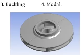
[image:4.595.351.506.542.647.2]3. Buckling 4. Modal.
Figure 5: Existing Impeller import to ANSYS
6.3 Boundary Conditions
Moment=3.896Nm
Level 1 Level 2 Level 3Material Cast iron Stainless steel Aluminium
Inlet
angle 30 45 60
No. of
blade 4 5 6
Sample
code Material Angle No. of blade
L1 Cast iron 30 4
L2 Cast iron 45 5
L3 Cast iron 60 6
L4 SS 30 5
L5 SS 45 6
L6 SS 60 4
L7 Aluminium 30 6
L8 Aluminium 45 4
© 2019, IRJET | Impact Factor value: 7.211 | ISO 9001:2008 Certified Journal
| Page 3086
Figure 6: Moment
Pressure = 0.15 Mpa
Figure 7: Applied Pressure
Fixed Support
Figure 8: fixed support
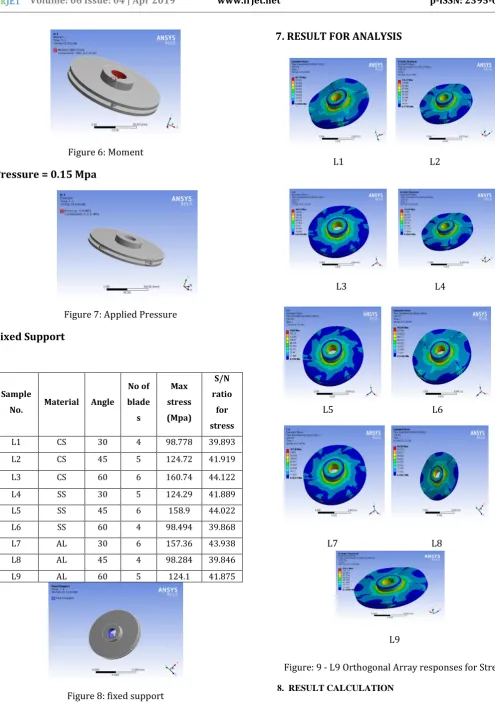
7. RESULT FOR ANALYSIS
L1 L2
L3 L4
L5 L6
L5 L6
L7 L8
[image:5.595.42.538.71.774.2]L9
Figure: 9 - L9 Orthogonal Array responses for Stress
8. RESULT CALCULATION
Sample
No. Material Angle
No of blade
s
Max stress (Mpa)
S/N ratio
for stress
L1 CS 30 4 98.778 39.893
L2 CS 45 5 124.72 41.919
L3 CS 60 6 160.74 44.122
L4 SS 30 5 124.29 41.889
L5 SS 45 6 158.9 44.022
L6 SS 60 4 98.494 39.868
L7 AL 30 6 157.36 43.938
L8 AL 45 4 98.284 39.846
© 2019, IRJET | Impact Factor value: 7.211 | ISO 9001:2008 Certified Journal
| Page 3087
Table 3: Output stress values and corresponding S/N ratios values for the experiments
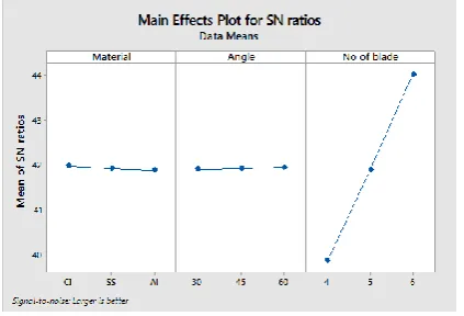
[image:6.595.30.271.109.310.2]The static analysis results of mean effects plot for means and for S/N ratio is shown in Fig. 10. In these results, the number of blades influences the most on static pressure while the blade angle influences the least. Since the aim is get the maximum stress value, Larger is better has chosen. Table 4 represents the maximum affecting parameters from analysis.
Figure 10: S/N ratio graph for stress
Level Material Angle No of blade
1 41.98 41.91 39.87
2 41.93 41.93 41.89
3 41.89 41.96 44.03
Delta 0.09 0.05 4.16
Rank 2 3 1
Table 4: Response Table for Signal to Noise Ratios (Larger is better)
Taguchi method cannot make judgment and determination on effect of individual parameters on entire process. The Results were analyzed using ANOVA for identifying the significant factors affecting the performance measures. The Analysis of Variance (ANOVA) is to investigate the design parameters and to indicate which parameters are significantly affecting the output parameters. In the analysis the sum of squares and variance are calculated. An F-test value at 95 % confidence level is used to decide the significant factors affecting the process. Larger F- value indicates that the varying the process parameters makes a big change on the performance. Table 5 shows the optimum combination of the fan from static analysis.
Table 5: Analysis of variance (ANOVA) results for the stress
Process parameter Level
Material CI
Outlet Angle 60
No of Blade 6
Table 6 : Orthogonal array L3 showed optimum value
As the centrifugal pump is used in very wide verity of applications so, it is quite necessary to measure the various pump performance parameters for the efficient operation of centrifugal pump, but Experimental studies to determine different performance parameters in different type of impeller material are complex, time consuming and costly. So by using ANSYS and DOE prediction model it is easy to predict the performance of different impeller material and speed up the production.
9. CONCLUSIONS
In this study, a centrifugal pump impeller optimized with the application of orthogonal experiment method. Major parameters like the Material, blade angle and number of blades of the fan were considered and analyzed. The ANSYS and Experimental approach helps to improve the results and the following conclusions were made.
• The result of max stress of impeller, which is obtained by analysis, is tabulated in L9 orthogonal array. Three process parameters
Sourc e
D F
Seq SS
Contri bution %
Adj SS
Adj MS
F-Val
ue P-Valu
e
Materi al
2 3.45 16.06 3.45 1.72 2.83 0.261
Angle 2 1.41 10.03 1.41 0.71 1.16 0.463
No of blade
2 28.23 70.89 28.2 64.1
1 45.4
7
0.120
Error 2 1.22 3.02 1.22 0.61
[image:6.595.53.265.457.601.2]© 2019, IRJET | Impact Factor value: 7.211 | ISO 9001:2008 Certified Journal
| Page 3088
were selected for geometrical design optimization of impeller.
• Analysis of results shows that number of blades and materials has the highest influence on the impeller stress. For changing the material from level 2 to level 3, the stress of pump decreases.
• For the optimal combination The analysis A 1, B3, C3 namely material –CI, Angle -60°, blade =6, carried out here using Taguchi Orthogonal array for optimization shows significant reduction in time consumption to find optimum design.
10. REFERENCES
[1] Cugal M and Bach’e G “Performance prediction form shutoff to runout flows for a complete st’,age of a boiler feed pump using computational fluid dynamics”, FEDSM97-3334, ASME Fluids Engineering Division Summer Meeting, 1997 [2] Edition, John Wiley & Sons.J.Gulich
,”Kreiselpumpen.Handbuch fur Entwicklung, Anlagenplanung und Betrieb”. 2nd edition, Springer, 2004.
[3] R.K.Rajput. Textbook of fluid mechanics and hydraulic machines Revised Edition, S.chand 2010
[4] Goto A, “Prediction of diffuser pump performance using 3D viscous stage calculation” FEDSM3340, ASME Fluids Engineering Division Summer Meeting, 1997.
[5] H.Albrecht and others,Laser Doppler and Phase Doppler Measurement Techniques”. Springer Verlag, Berlin, 2002
[6] H.Albrecht and others,”Danvak. Varme-ogklimateknik.Grundbog”.2ndedition.