Abstract— This paper describes the development and evaluation of a novel effort control system for cycling, which contributes to promote the users’ mobility and physical health. This system provides automatic control of the motor assistance level of an electric bicycle in order to ensure that the cyclist’s effort remains inside the desired target zone, regardless of changes in other variables which normally affect the effort, such as the slope of the road. The system presented in this paper controls the pedaling resistance perceived by the cyclist through the use of a sensor device placed inside of the bicycle crankset, which provides the required torque signal. The data processing, effort control algorithm and user interface are implemented in a smartphone application, whereas a microcontroller on the bicycle is responsible for the data acquisition, wireless data exchange with the smartphone, and real-time control of the motor assistance level. Experimental results validate the effectiveness of the implemented effort control system.
Index Terms— Effort control, electric bicycles, mobile sensing, torque, wireless sensor networks.
I. INTRODUCTION
Recent advances in the miniaturization and integration of sensors into popular consumer products, such as smartphones, enable the design and development of several new applications, creating a concept called mobile sensing, which consists of sensor data collection focused on people [1] through their mobile devices. Smartphones are steadily becoming the core communication and processing devices in the people’s lives, making the study and development of mobile sensing systems an attractive emerging area of research and development [2], [3].
The system proposed in this paper allows the provision of automatic effort control, based on the use of an electric bicycle and a smartphone, in order to assure that effort (expressed by the pedaling resistance, in this case) remains at the desired level regardless of changes in other variables, such as the slope of the terrain or the velocity of the bicycle. Therefore, this system contributes to promote the users’
Manuscript received March 19, 2015. This work has been supported by FCT (Fundação para a Ciência e Tecnologia) in the scope of the projects PEst-OE/EEA/UI04436/2015 and PEst-UID/CEC/00319/2013.
José A. Afonso is with Department of Industrial Electronics and MEMS-UMinho, University of Minho, Campus of Azurém, Guimarães, 4800-058, Portugal (phone: 351-253510190; fax: 351-253510189; e-mail: [email protected]).
Filipe J. Rodrigues is with Centro Algoritmi, University of Minho, Portugal (e-mail: [email protected]).
Delfim Pedrosa is with Centro Algoritmi, University of Minho, Portugal (e-mail: [email protected]).
João L. Afonso is with Department of Industrial Electronics and Centro Algoritmi, University of Minho, Portugal (e-mail: [email protected]).
mobility and physical health by combining the advantage of control of the exercise intensity, which is typical of stationary bicycles, with the benefit of outdoor physical activity provided by conventional bicycles.
The proposed system allows a heterogeneous group of people with different physical conditioning (e.g., family members and friends) to ride together along the same track, each one at the most adequate exercise intensity level, given factors as age, gender, health condition and fitness level, contributing to the engagement and enjoyment of the physical activity by all members of the group.
This system is also envisioned to be used at home, for example, in the days when the weather is not suitable for outdoor cycling. In this scenario, the electric bicycle is placed on a support and the desired level of resistance is provided by the electric motor. Besides eliminating the costs associated to the acquisition of an indoor bicycle, this operation mode allows the user to benefit of the monitoring and control functionalities provided by the proposed system.
This system has also the benefit of increasing the convenience of bicycles as a transportation medium in areas with ascents and declines, which typically have poor adherence to this type of transportation, since the user does not have to be bothered to manually adjust the motor assistance. Nevertheless, the user has the option to disable the automatic control and switch to manual operation at any time.
The main contribution of this paper is the description of the design, implementation and evaluation of an automatic effort control method, applied to cycling, based on the measurement of the pedaling resistance perceived by the cyclist.
This paper is organized as follows. Section II presents previous research work related to this paper. In Section III, an overview of the design and implementation of this effort control system is provided, with emphasis on the electric bicycle components. Section IV describes the sensor data processing and the effort control algorithm implemented on the smartphone application, whereas Section V presents results from the experimental tests and the corresponding discussion. Finally, Section VI presents the conclusions and perspectives of future work.
II. RELATED WORK
Previous related research works describe systems that take advantage of the use of mobile devices with bicycles in order to monitor sensor data from the user’s body [4], [5], the bicycle or the environment, with the aim to enhance the users’ experience.
Automatic Control of Cycling Effort Using
Electric Bicycles and Mobile Devices
The BikeNet project [6] uses sensors adapted to a conventional bicycle in order to monitor several parameters. The developed system consists of a wireless sensor network [7], [8] based on the IEEE 802.15.4 standard [9]. The mote platform that was used is based on TinyOS and provides multiple sensors, such as a 2-axis accelerometer, a thermistor and a microphone. This system uses an IEEE 802.15.4/Bluetooth gateway to provide the interface between the sensor network and a smartphone. Data monitoring focuses on parameters such as speed, geographical location, noise, CO2 levels, user’s stress level and detection of cars in close proximity using magnetometers.
Marin-Perianu et al. [10] present a solution and respective performance analysis for measurement of knee and ankle joint angles based on wireless motion sensor nodes that gather sensor data using inertial measurement units (IMUs) and provide immediate feedback to the cyclists about their pedalling movement.
The Biketastic platform [11] aims to create a system where cyclists can share their routes and experiences. Information collected using the smartphone sensors includes the roughness of the road and the level of audible noise. The smartphone application also allows the users to capture geo-tagged images and video clips while riding, and insert tags and descriptions.
Walker et al. [12] describe a system for collecting signals from a cyclist and a conventional bicycle, with emphasis on the developed network sensor nodes. The system is composed by multiple wireless sensor nodes based on ZigBee [13]. The developed equipment is used to collect data such as temperature and heart rate of the cyclist, the ambient temperature and the angular velocity of the bicycle wheel. This system uses a laptop (instead of a mobile device) installed on the handlebars, which receives, via Bluetooth, the data collected by the ZigBee coordinator from all sensor nodes.
Outram et al. [14] developed a wheel, in the context of the Copenhagen Wheel project, which can be adapted in a conventional bicycle in order to turn it into an electric bicycle. The central part of the wheel (hub) integrates an electric motor, a battery and internal gears, as well as environmental sensors for monitoring of noise, temperature, humidity, CO and NOx levels. This system is enhanced with mobile sensing capabilities through the use of an iPhone smartphone, which communicates with the hub using Bluetooth. The smartphone provides geographical location
and allows the user to manually lock/unlock the bike, change the gear and adjust the level of assistance of the electric motor.
Giani et al. [15] present a cyclist’s heart rate control system through a continuously varying transmission (CTV), where the main goal is to maintain the heart rate value specified by the cyclist [16]. The control system is implemented in a city bicycle that is equipped with a NuVinci roller-based CVT controlled by an electronic control unit (ECU). The ECU also measures the pedal torque, pedal speed and rear speed. The system is composed by a heart rate monitor, a smartphone and an ECU, which communicate with each other via Bluetooth. The ECU is responsible to run the low level CTV control, while the smartphone runs the heart rate control algorithm.
Nagata et al. [17] describe a control system to keep the continuous level of exercise intensity around the aerobic threshold. The control uses a new pedaling rate control system that works with an efficient pedaling rate of a popular bicycle for aerobic exercise while cycling. An oxygen mask was also used to read the oxygen uptake per second. With this control system the average oxygen uptake per second was significantly improved when compared with other type of assisted mode. This system can be applicable for any bicycle where the range of specific pedaling rate of the electric motor assistance is in accordance with the preferred pedaling rate.
Unlike these previous works, this paper proposes a novel effort control method which allows the automatic control of the pedaling resistance based on the measurement of the torque.
III. SYSTEM OVERVIEW
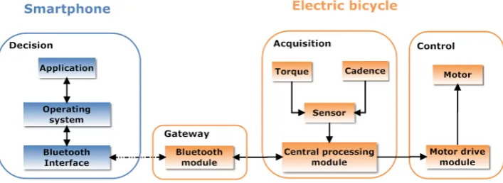
The main components of the proposed system are a smartphone and an electric bicycle, as shown in Fig. 1. The smartphone contains a decision block, whereas the bicycle integrates an acquisition block composed by a central processing module and sensors; a control block containing the motor drive module and the motor; and a gateway.
[image:2.595.121.475.629.758.2]The developed application on the smartphone interfaces with the user and implements the effort control algorithm, which is responsible for the decision regarding the motor assistance level to be applied, at each moment, during the cycling activity, based on pre-defined user profiles. This application uses Bluetooth to communicate with the bicycle.
The central processing module of the acquisition block is responsible for periodic reading and pre-processing of the torque signal, which is necessary for implementation of the effort control method based on the pedaling resistance. This signal is obtained from a torque and cadence sensor, and is sent to the smartphone application using the gateway (Bluetooth module). The cadence signal is not used in the context of this effort control method.
A. Information Flow
After the smartphone application performs the authentication with central processing module of the bicycle, it gives the user the choice of the assistance mode. The user is allowed to select between two modes of assistance: Manual mode, which provides two buttons on the smartphone display for the user to increase or decrease the motor assistance manually; and Automatic mode, which provides automatic effort control based on the selected control mode. If the Automatic mode is selected, the user then chooses the effort control mode.
Although this paper discusses only one effort control mode, based on the pedaling resistance (where only the measured torque is considered in the developed control algorithm for deciding the level of assistance to apply to the electric motor), the system was designed to allow the selection of other effort control modes, if available. For example, an effort control mode based on the power output could also be available. In this case, the control algorithm would need to consider both the cadence and torque in order to decide the motor assistance level.
All these user choices can be pre-configured in the application, avoiding the need for user interaction each time a cycling activity begins.
After this startup phase, if the automatic mode was chosen, the system enters in a loop which is executed systematically until the cycling activity ends. During this process, a microcontroller on the central processing module is responsible for measuring the torque signal, the cadence signal and the battery level of the electric bicycle. After acquiring this information, the microcontroller builds and sends a data frame to the smartphone through the gateway.
The application on the smartphone processes the data received and executes the effort control algorithm. Finally, this application builds the control frame and sends it back to the central processing module, which interprets the decision and communicates it to the motor drive module in order to adjust the assistance level.
B. Electric Bicycle Components
The electric bicycle used in the implementation and evaluation of the proposed effort control system is a prototype developed at University of Minho that was already available at the beginning of this work. It was built upon a conventional bicycle and provides a BLDC (Brushless DC) motor, a lithium polymer battery with nominal voltage of 36 V and nominal capacity of 10 Ah, a motor drive module, and a small module at the handlebars with manual control buttons and a LCD display. This electric bicycle was originally prepared to operate with three levels of assistance, but it was modified to operate with 10 levels for this work.
[image:3.595.306.548.122.312.2]Fig. 2 shows the location of the physical components on the bicycle. In addition to the components already present on the original electric bicycle, this system introduces only a torque and cadence sensor, a central processing module and a Bluetooth gateway.
Fig. 2. Electric bicycle used in this work with the installed components.
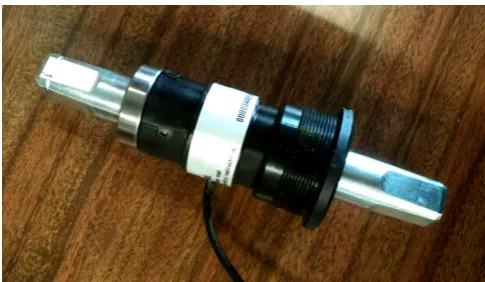
The sensor chosen to provide the values of torque and cadence is shown in Fig. 3. This sensor presents several advantages over other solutions. It is strategically placed inside of the crankset, giving the advantage of being invisible and ensuring protection against external environment factors, such as oil, water, dust and vibrations from the terrain, thus eliminating major maintenance requirements. In addition, the fact that it is designed to be placed inside standard cranksets provides compatibility with most types of bicycles and avoids the need of calibration each time the bicycle is disassembled for transport.
Fig. 3. Torque and cadence sensor used in this work.
The cadence signal consists of pulses that are generated as the pedal is rotated (8 pulses for a full 360° rotation), whereas the torque signal is analog and presents a linear behavior, with sensor sensitivity of 10 mV/Nm and range from -200 Nm to +200 Nm.
[image:3.595.304.547.476.617.2]be aggregated into a data frame.
This microcontroller uses its universal asynchronous receiver/transmitter (UART) interface to communicate with the Bluetooth gateway, and its serial peripheral interface (SPI) to communicate with the motor drive module. The central processing module and the motor drive module use the same type of microcontroller.
The Bluetooth module provides a UART interface that is used to communicate with the central processing module and a Bluetooth radio interface which communicates with the smartphone. This Bluetooth module can operate in two ways: data mode (default) or command mode. In the data mode it functions as a tunnel, i.e., when data is received over the Bluetooth interface, the headers of the Bluetooth protocol are removed and only the user data is sent to the UART interface. Similarly, when user data is received form the UART interface, the Bluetooth module builds the Bluetooth packet and sends it to the destination. The command mode is triggered whenever the UART or Bluetooth interface receives a pre-defined sequence of characters.
IV. SMARTPHONE APPLICATION
The smartphone is a fundamental component of the proposed system. The main tasks performed by the smartphone application are: the processing of the data generated by the torque and cadence sensor; and the execution of the effort control algorithm, which makes use of the processed data. The application was developed and tested using an Android smartphone.
A. Sensor Data Processing
One problem encountered during the development of the effort control system based on the pedaling cadence is that the torque signal provided by the sensor device presents very large variations as the cyclist presses and releases the pedal, as shown in Fig. 5.
Therefore, in order to enable the effort control algorithm to work properly, it was necessary to implement a mechanism to smooth abrupt changes in the torque signal, in order to provide a more predictable input to the control algorithm and, consequently, to avoid undesired changes on the motor assistance level.
The conceived solution reduces the variation of the effort parameter (torque) using the exponentially weighted moving average (EWMA) technique. This technique has the particularity of assigning greater weight to more recent values (with the importance of past values decreasing exponentially over time). It also integrates all past data in a single value, decreasing the amount of memory and processing required. This technique uses the following equations:
0
,
=
=
X
k
S
k k (1)0
,
)
1
(
−
1>
+
=
−
k
S
X
S
kα
kα
k (2)The value of effort calculated using the EWMA technique (Sk) uses a factor (0 ≤ α ≤ 1) which determines the weight to
assign to the current sample (Xk), in contrast with the
previously calculated value (Sk-1). Smaller values of α
increase the level of smoothing but make the result less responsive to recent changes in the data, and vice-versa. The domain k is the set of natural numbers, and for k = 0 the result takes the value of the first sample (X0).
B. Effort Control Algorithm
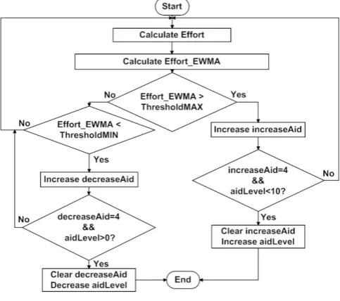
The flowchart of Fig. 4 illustrates how the effort control algorithm of the smartphone application was implemented. After receiving the sensor data, the smartphone calculates the effort (torque, in this case) that the cyclist is applying at that instant. After that, it uses the EWMA equations to calculate a new effort value without abrupt variations. If the resulting value (Effort_EWMA) exceeded the maximum threshold defined on the profile (thresholdMAX), the variable increaseAid in incremented (the variables increaseAid and decreaseAid are used to avoid premature increase/decrease on the motor assistance level). After that, a joint verification is performed: if the motor assistance level (aidLevel) is lower than the maximum level (10) and increaseAid is equal to 4 (this is a pre-defined value that can be decreased/increased if desired to provide faster/slower transitions between assistance levels). If this result is false, the processing returns to the start of the algorithm; otherwise, the variable increaseAid is cleared and the variable that contains the current value of the motor assistance level (aidLevel) is incremented.
[image:4.595.306.548.513.727.2]For the case where the EWMA effort did not exceed the maximum threshold, it is checked whether it decreased below the minimum threshold (thresholdMIN); if the result is false, the processing returns to the start of the algorithm; otherwise, the variable decreaseAid is incremented and another joint verification is performed: if aidLevel is higher than the minimum motor assistance level (0) and decreaseAid is equal to 4. If this result is false, the algorithm returns to the start; if both conditions are verified, the variable decreaseAid is cleared and aidLevel is decremented.
Fig. 4. Effort control flowchart.
condition essentially serves to guarantee that the motor assistance level is not hastily changed whenever there is only a momentary oscillation in the effort of the cyclist.
V. RESULTS AND DISCUSSION
This section presents experimental tests conceived to compare the measured effort (pedaling resistance) without and with the effort control mechanism enabled. These tests were performed with the rear wheel placed on a support that allows the adjustment of the resistance applied to the bicycle. The EWMA parameter was set to α = 0.1 and the sampling time was configured to 200 ms.
[image:5.595.308.548.48.254.2]During these tests, the cadence was kept constant. Fig. 5 concerns the monitoring of the pedaling resistance felt by the cyclist (which corresponds to the measured torque) over time, without any control. In this figure, the instantaneous torque calculated directly from the collected sensor data (Instant. torque) is represented in blue, and the smoothed torque, obtained by applying the EWMA technique (EWMA torque), in green. When the effort control algorithm is active, this value is used by the algorithm to compare with the defined threshold values, which are represented in black. The red curve presents the average effort calculated using a moving average centered on the current EWMA value (Avg. EWMA torque). These values are more representative of the current effort felt by the cyclist, yet the effort control algorithm used the values presented in green, because the red curve relies on samples available a posteriori, i.e., the moving average contains past and future values, which prevents the calculation in real-time.
Fig. 5. Pedaling resistance without effort control.
For this test, up to 30 s, the resistance applied to the rear wheel support was set at a minimum value. From 30 to 50 s the resistance provided by the support was increased to its maximum value, which was maintained up to 70 s. After 70 s the resistance was gradually decreased. Through Fig. 5, it can be seen that the upper horizontal line, corresponding to the maximum threshold value, is exceeded during long periods by the EWMA torque values, which indicates that there is no resistance control for this case.
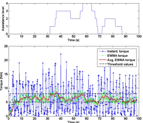
[image:5.595.48.288.434.589.2]Another test under the same conditions, but with the effort control algorithm enabled, was conduct. Fig. 6 presents both the torque over time and the corresponding motor assistance level that was set by the algorithm.
Fig. 6. Pedaling resistance with effort control.
After 30 s, the resistance applied by the rear wheel support was increased, which resulted in the EWMA torque exceeding the limits allowed by the effort control algorithm, resulting in the need for increased motor assistance to compensate this excess. The assistance level increased gradually along with the applied resistance until it reached level 4 around 60 s. After that the motor assistance level decreased as the resistance applied to the support also decreased.
These results show that the proposed effort control system is able to provide to the cyclist a level of pedaling resistance (torque) approximately constant (taking into account the range of variation allowed by the thresholds configured on the user profile), regardless of the resistance applied on the support, due to the provision of automatic control of the motor assistance.
VI. CONCLUSIONS
This paper proposed a system applied to cycling that enables the automatic control of the pedaling resistance based on the use of a smartphone and an electric bicycle. The presented experimental results validate the proposed system, which has applications on fitness, transportation and healthcare.
In the future, two other effort control methods based on the power output and the heart rate will also be implemented on the system. Besides the torque signal, the power output mode requires also the cadence signal, which is already provided by the sensor device that is currently being used. With respect to the heart rate mode, all the required hardware is also already available on the current system, except the Bluetooth heart rate sensor, which was already acquired. The next steps will be the adaptation of the effort control algorithm in order to handle these effort control methods and the execution of experimental tests in order to validate the new developments.
implemented on the smartphone application, enabling programmable routines with effort control based not only on the pedaling resistance but also on the power output and heart rate.
Future work will also include the integration of the embedded codes of the microcontrollers located on the central processing module and the motor drive module into a single microcontroller, which may reduce even more the overall size and cost of the system.
In parallel with this work, two other mobile sensing systems applied to cycling were developed. The first one provides a database, available both on a smartphone and online through a web browser, with georeferenced information regarding multiple relevant cycling variables, such as velocity, altitude, slope and roughness of the terrain, route, torque, cadence, power output and heart rate. The second one allows the monitoring of the posture (e.g., trunk and knee angle) of cyclists, anywhere and in real-time, using wireless motion capture sensors [18] that communicate with the smartphone using Bluetooth Low Energy (BLE) [19]. In the future it is planned to integrate the functionalities provided by all these systems into a single application.
REFERENCES
[1] A. T. Campbell, N. D. Lane, E. Miluzzo, R. A. Peterson and S. B. Eisenman, “The rise of people-centric sensing,” IEEE Internet Computing, vol. 12, no. 4, pp. 12-21, Jul. 2008.
[2] W. Z. Khan, Y. Xiang, M. Y. Aalsalem and Q. Arshad, “Mobile phone sensing: A survey,” IEEE Communications Surveys & Tutorials, vol. 15, no. 1, pp. 402-427, 2013.
[3] N. D. Lane et al., “A survey of mobile phone sensing,” IEEE Communications Magazine, vol. 48, no. 9, pp. 140-150, 2010. [4] M. Chen, S. Gonzalez, A.Vasilakos, H. Cao and V. C. M. Leung,
“Body area networks: A survey,” Mobile Networks and Applications, vol. 16, no. 2, pp. 171-193, 2011.
[5] M. Patel and J. Wang, “Applications, challenges, and prospective in emerging body area networking technologies,” IEEE Wireless Communications, vol. 17, no. 1, pp. 80-88, 2010.
[6] S. B. Eisenman et al., “BikeNet: A mobile sensing system for cyclist experience mapping,” ACM Transactions on Sensor Networks, vol. 6, no. 1, pp. 1-39, 2009.
[7] C. Buratti, A. Conti, D. Dardari and R. Verdone, “An overview on wireless sensor networks technology and evolution,” Sensors, vol. 9, no. 9, pp. 6869-6896, 2009.
[8] J. Yick, B. Mukherjee and D. Ghosal, “Wireless sensor network survey,” Computer Networks, vol. 52, no. 12, pp. 2292-2330, 2008. [9] IEEE Std 802.15.4-2006, “IEEE standard for local and metropolitan
area networks - Part 15.4: Wireless medium access control (MAC) and physical layer (PHY) specifications for low-rate wireless personal area networks (WPANs),” Sep. 2006.
[10] R. Marin-Perianu et al., “A performance analysis of a wireless body-area network monitoring system for professional cycling,” Personal and Ubiquitous Computing, vol. 17, no. 1, pp. 197-209, 2013. [11] S. Reddy et al., “Biketastic: sensing and mapping for better biking,”
in Proc. of the SIGCHI Conference on Human Factors in Computing Systems, Florence, Italy, 2010, pp. 1817-1820.
[12] W. Walker, A. L. P. Aroul and D. Bhatia, “Mobile health monitoring systems,” in Proc. 31st Annual International Conference of the IEEE EMBS, Minneapolis, Minnesota, Sep. 2009, pp. 5199-5202. [13] E. D. Pinedo-Frausto and J. A. Garcia-Macias, “An experimental
analysis of Zigbee networks,” in Proc. 33rd IEEE Conference on Local Computer Networks, Montreal, Canada, Oct. 2008.
[14] C. Outram, C. Ratti and A. Biderman, “The Copenhagen Wheel: An innovative electric bicycle system that harnesses the power of real-time information and crowd sourcing”, in Proc. EVER'2010, Monaco, Mar. 2010.
[15] P. Giani, M. Corno, M. Tanelli and S. M. Savaresi, “Cyclist heart rate control via a continuously varying transmission,” in Proc. 19th World Congress of The International Federation of Automatic Control, Cape Town, South Africa, Aug. 2014, pp. 912-917.
[16] M. Corno, P. Giani, M. Tanelli, and S. M. Savaresi, “Human-in-the-loop bicycle control via active heart rate regulation,” IEEE Transactions on Control Systems Technology, vol. PP, no. 99, Oct. 2014.
[17] T. Nagata, S. Okada and M. Makikawa, “Electric motor assisted bicycle as an aerobic exercise machine,” in Proc. 34th Annual International Conference of the IEEE EMBS, San Diego, California, Aug.-Sep. 2012, pp. 1933-1935.
[18] J. A. Afonso, J. H. Correia, H. R. Silva, L. A. Rocha, “Body Kinetics Monitoring System,” International Patent WO/2008/018810A2, Feb. 2008.