Abstract—The fifth generation (5G) wireless communication offers various new advanced features which makes it effective and in huge demand in the future. The 5G wireless communication system provides promising technology such as massive MIMO and is widely investigated. One noteworthy issue that should be tended to in connection to massive MIMO technology is mutual coupling, and the development of successful decoupling techniques to balance the performance degradation by this effect. In this paper, we evaluate the performance of massive MIMO system and its coexistence with inserted decoupling scheme for small receiving monopole array. Mutual coupling between the monopole array is characterized by the receiving mutual impedance method (RMIM), to formulate the decoupling network operating matrix and design. A typical channel model of standard massive MIMO is presented, the system performance is evaluated when coupling effects existed and after decoupling process. System performance results support our conclusions that the output voltages of decoupling network can effectively be removed off the coupling effect. However, the coupling matrix created can have effect on the channel coefficients, and thereby degrading the bit error performance of receiving array in massive MIMO system.
Index Terms—Coupling matrix, cross correlation coefficient, inserted decoupling scheme, mutual coupling, receiving mutual impedance
I. INTRODUCTION
S the demand for high data rate is increasing exponentially, wireless designers have proposed and started research into fifth generation wireless system. The proposed 5G system provides promising technologies such as massive MIMO, energy-efficient communication, cognitive radio networks and many more. In addition to inheriting the benefits of conventional MIMO systems, a massive MIMO system can also significantly enhance both spectral efficiency and energy efficiency. One of the challenges of MIMO antenna design is the task of enhancing the isolation between ports closely located within restricted space in mobile handset. This is because of the way the array elements have to be contained in a reduced
Manuscript submitted February 14, 2016; received February 15, 2016; accepted February 16, 2016; The authors are with the Center for RFIC and System Technology, School of Communication and Information Engineering, University of Electronic Science and Technology of China, Chengdu 611731, P. R. China; e-mail: [email protected]
volume, which brings about substantial pattern/spatial correlation and strong mutual coupling effect between the elements. It is a common conclusion that mutual coupling influences the performance of antenna arrays, as increase in correlation restricts the channel capacity. Moreover, if mutual coupling is strong, a large portion of the power fed into one port will be coupled to the other port rather than radiating to free space; consequently diminishing the signal-to-noise ratio, radiation sufficiency and channel capacity.
Therefore, building up a successful decoupling technique to balance the performance degradation in MIMO antennas by mutual coupling effects has attracted the attention of the academic society recently. Different decoupling strategies have been proposed [1], and can be separated into four classes: 1) Eigen-mode Decomposition Scheme: Its guideline is to diagonalize the scattering matrix of a compact array using
90
and /or180
[2]-[6]. 2) The Inserted Component Scheme: It works on the concept of inserting a section of transmission-line between the coupled antenna ports [7]-[11]. 3) Artificial Structure Decoupling Scheme: This method uses sub-wavelength EM structures such as electromagnetic band gap (EBG) structure [12], defected ground structures (DGS) [13], and magnetic metamaterials [14], [15]. 4) Coupled Resonator Decoupling Scheme: This method was proposed for the first time in 2014, and has the concept of decoupling pair of coupled elements using coupled resonators [1] and [16]-[19]. To give the full picture of the performance of decoupling schemes, several important figures of merit are utilized by researches including: isolation, radiation efficiency, envelope correlation coefficient (ECC), channel capacity, and throughput.However, the effects of coupling matrix on the channel coefficients and the resulting consequences on the bit error rate (BER) are rarely accounted for or studied in the signal processing or communication literature. Massive MIMO is well studied, however its coexistence with decoupling network schemes needs further investigations. Our objective in this paper is to present the influence of decoupling matrix of inserted decoupling scheme on average BER in typical channel model of standard massive MIMO system. We demonstrate that the output of the inserted decoupling network can adequately be removed off the decoupling effect, however, the bit error performance is degraded as a result of correlation effects of coupling matrix on channel coefficients.
Evaluation of Small
Receiving Monopole Array
with Decoupling Networks
in Massive MIMO
System
Affum Emmanuel Ampoma, Guangjun Wen and Oteng Gyasi Kwame
The outline of the paper is as follows: Section II presents the receiving mutual impedance, formulation of coupling effect and the design of the inserted decoupling scheme. Massive MIMO System model and coupling matrix are described in Section III. Section IV presents simulation results and discussions. Finally, we give concluding remarks in Section V.
II. DESIGN OF THE INSERTED DECOUPLING SCHEME
A. Receiving Mutual Impedance Formulation for the Mutual Coupling Effect
Receiving mutual impedance method is used to characterize the mutual coupling effect between two receiving monopoles for the study. The two parallel monopoles operating at 2.4 GHz are placed on a metallic ground plane and connected to a
Zo
= Ω
50
load. The monopoles have length of 30 mm, radius of 2 mm and element separation of 25mm (0.2λ
at 2.4 GHz). For the measurement set up in Fig. 1, the transmitting antenna is a horn antenna working between 2-4 GHz, whereas a separation of 50 mm is given between transmitting antenna and receiving monopole array. Considering the concealed impacts of the metallic ground, Fig. 2 shows the measured S-parametersS
21(1),S
21(2) andS
11 utilizing the procedure in [20]. Ifγ
is complex and represents the square root of the transmitted power, the respective terminal voltages can be calculated as [21]
V
21(1)=
S
21(1)γ
Zo
,V
21(2)=
S
21(2)γ
Zo
andV
11=
S
11γ
Zo
(1) The voltage and current relationships can be expressed as (1) (2)21 11 12 t
V
=
V
+
Z I
(2) and12
Z
=
(1) 21(1) (2) 21(2) 0,
t t oV
V
I
I
Z
Z
=
=
and 11t o
V
I
Z
=
(3) After some manipulations, the mutual coupling between array elements is expressed as(1) 11 21 12 (2) 21 o
V V
Z
Z
V
−
=
(1) 11 21 (2) 21 oS
S
Z
S
−
=
(4) Consider a receiving antenna with array ofN
elements, the relationship between the uncoupled voltages(k 1,2,..., )
k
U
=
N
and the received coupled voltagesV
k can be written in a matrix notation as [22]2 12 1 1 2 21 2 1 2 1 1 1 IN L L N L L N N N N Z Z Z Z U V Z Z U V Z Z V
U Z Z
Z Z − − − − − = − −
(5)
where
Z
tki represents the mutual impedance between thekth
and theith
antenna elements andZ
Lis the terminal impedance connected to the antennas.B. Decoupling Network Operating Matrix and Design
The compensation network consists of a power-divider with unequal power-dividing ratio and two rat-race couplers. The network uses no active circuit elements to minimize extra circuit noise [23]. As shown in Fig. 3, the power divider has three transmission lines, each having characteristic impedance of
2
Z
o, whereZ
o is the system’s characteristic impedance, but unequal electrical lengths. The electrical lengthθ
can be calculated as [29]
θ
cos
11
β
−
=
(6) whereβ
is the dividing ratio of the power dividerexpressed as
1
12t
z
β
=
and12 12 t t L
Z
z
Z
=
(7)From (5) the matrix operation of the decoupling network is expressed as
12 12
1 2
1 1
2 21 2 21
2 1
1
1
L L
L L
Z
V
Z
V
Z
Z
U
V
U
Z
V
V
Z
V
Z
Z
−
−
=
=
−
−
(8) [image:2.595.320.540.593.733.2]where
V
1 andV
2 are the couple voltages and the inputs to the network from the monopole terminals and the output voltages areU
1 andU
2, also known as the compensation voltages. We fabricate the circuit by using the substrate FR4 with dielectric constant 4.8 at operating frequency of 2.4 GHz as shown in Fig. 3. The measured insertion loss between input and output ports of the decoupling network are shown in Fig. 4.Fig 1. Measurement of receiving mutual impedance of receiving monopole array in anechoic chamber.
III. SYSTEMMODEL
A wireless system with typical channel model of standard massive MIMO is presented among users and base stations (BSs) [27]. In this paper, a
R R Z
(
∈
)
cell wireless system is considered and every cell comprises of a BS with A antennas and B users. The average transmit power of each BS antenna is represented byP
t andP
rindicating the average transmit power of user antenna. The BS of l-th(0
< ≤
l R
)
cell is l-th BS. The propagation factor between the l-th BS and the k-th user of the j-th(0
< ≤
j R
)
cell isα
ljk, the propagation factor among the l-th and the j-th BS isα
lj.The channel vector between the l-th BS and the k-th user of the j-th cell is
h
ljk∈
V
M×1. Thus, in the l-th cell, the channel vector between the k-th user and the BS ish
ljk. The channels are considered to be frequency-flat andljk
h
remains constant during the coherence intervalT T
(
τ
)
.τ
is the length of pilots. The channels are assumed of reciprocity, the channel factors are identical for both forward and backward link. If the channel matrix between the l-th BS and the j-th BS isH
lj∈
V
M M× , thenT
jl lj
H
=
H
. The n-th row, m-th column ofH
ljisH
ljnm, representing the coefficient between the n-th antenna of thel-th BS and the m-th antenna of the j-th BS. Downlink communication is considered in this paper.
The transmitter, typically the base station (BS), is highly elevated and not obstructed, with transmit antennas widely separated. Although the spatial correlation might exist at the transmitter because of the absence of scatterers at the surrounding environment, we just consider impacts of mutual coupling and channel correlation at the receiver where multiple antennas are placed closely to each other due to the relatively limited space. Hence, the channel
H
is given by [27]1/2 0 m
H Z R H
=
(9) whereH
0 is theB A
×
channel matrix under independent, identically distributed channel fading. Each entry ofH
0 is a random variable with zero-mean and unity variance.Z
m andR
1/2 denote the mutual coupling and spatial correlation matrices at the receiver respectively.12 1
(
)(
)
m A T T
Z
=
Z
+
Z Z
+
Z I
−where ZA is the antenna impedance in isolation , I is identity matrix, ZTis the impedance of the receiver at each antenna element, chosen as the complex conjugate of ZA
and Z12is the mutual impedance.
The expression for channel capacity can be written as the following
1/2 1/2
2 0 0
( ) log det(
H H H)
N m m
C H
I
H R Z Z R H
A
ρ
=
+
(10)2 2
( [ ( ) ( ) ]) /
H/
tr E x t x t
N
ρ
=
σ
=
σ
. This is theaverage SNR per receive antenna. The received signal is
1/2 0
( )
( )
( )
m( )
Y t
=
HX t n t
+
=
Z R H
+
n t
(11)1 2
( ) [ ( ), ( ),..., ( )]
T Bn t
=
n t n t
n t
is the complex additive white Gaussian noise (AWGN) vector with zero-mean and varianceσ
2/ 2
in each complex dimension.[image:3.595.310.528.230.423.2]
Fig. 2. Measured receiving mutual impedance of two quarter-wavelength side by side monopole receiving array (the inset shows measured s-parameters).
A. Error Performance
The generalized average error probability performance of M-PSK over fading channels is expressed as [28]
2 ( 1) /M
2
0 0
2 ( 1) /M
2
0 0
1
exp
( )
2sin
1
exp
( )
2sin
M
M
a
k
d p
d
a
p
d d
π
γ
π
γ
γ
θ
γ γ
π
θ
γ
γ γ θ
π
θ
∞ −
− ∞
=
−
=
−
∫ ∫
∫
∫
(12)
where
a
2=
2sin
2π
/
M
, after simple mathematical manipulations (12) becomes
2 ( 1) /M
2 0
1
2sin
M
a
k
π
πM
γθ
d
θ
−
=
−
∫
(13)In Rayleigh fading channel, error performance is expressed as
1 2 ( 1) /
2 0
1
( , , )
1
2sin
M M
r
a
k k a
γ
M
πγ
d
θ
π
θ
−
−
=
+
∫
2
2
2 1
2
/ 2
1
...
1
/ 2 (
1)
1
/ 2
...
tan
cot
2
1
/ 2
a
M
a
M
M
M
a
a
M
γ
γ
π
π
γ
π
γ
−
−
×
+
−
−
=
×
+
+
[image:4.595.311.544.51.249.2]where
γ
is the average signal to noise ratioFig.3. Photograph of the fabricated inserted decoupling network.
IV. SIMULATION RESULTS AND DISCUSSIONS
For illustration, coupling matrices under two different conditions are determined in an anechoic chamber using the set up in Fig.1, and incorporated into the system model for error performance analysis. In the first place, the scattering parameters on the coupled monopole array are measured to determine coupled voltages (
V
1 andV
2) and coupling matrix. This has been clarified in Section II. Secondly, the monopole antennas in the array are connected to the decoupling network through equivalent length coaxial links and scattering parameters of the output ports of the decoupling network are measured to determine the coupling matrix for the compensated voltages (U
1 andU
2).There are three different types of voltages listed in Table I. The last row in Table I is a ratio of the voltage obtained with monopole B to the voltage obtained with monopole A. It can be seen that the ratio of the compensated voltage is very close to the uncoupled voltages, demonstrating that the compensated voltages have successfully been removed off the coupling effect. On the other hand, the variations of cross correlation coefficients
( )
ρ
12 recorded by the procedure in [30] under the two conditions demonstrated the lesser impacts of coupling on the compensated voltages. Coupling is included in the massive MIMO system in a Rayleigh fading environment with QPSK modulation where the recorded cross correlation coefficients were 0.74 and 0.68 for the coupled voltages and 0.35 and 0.24 for compensated voltages respectively.Fig.4. Measured insertion losses between input and output ports of the decoupling network.
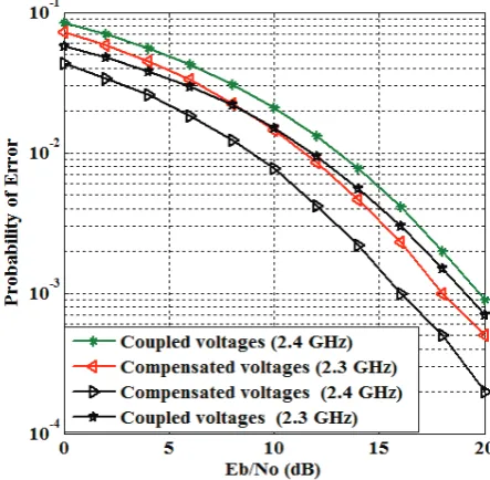
The 2*2 MIMO results shown in Fig. 5 indicates that for error probability of10−3, the performance of the compensated
voltages must incur losses of
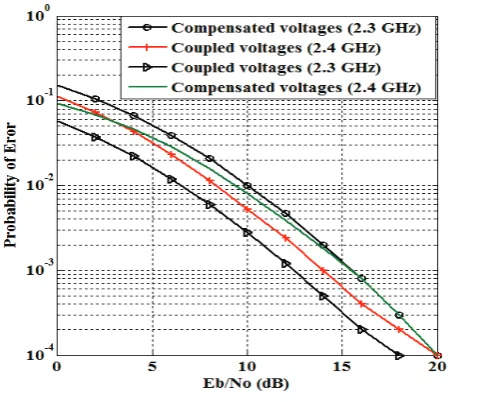
2
dB
and 3dB to create comparable results for the coupled voltages at 2.4 GHz. Similar results are recorded in Fig. 6 and Fig. 7 with enhanced SNR for 4*2 MIMO system. In the event that coupling affects the performance of antenna arrays, our outcomes demonstrate an opposite case. The lowest cross correlation coefficient recorded betweenU
1andU
2 did not interpret into exceptionally improved bit error performance. It is not therefore practical to conclude that mutual coupling is an undesired effect, particularly when coupling matrix is incorporated into the channel network for error performance evaluation. This is on the grounds that we provided results to support that coupling matrix can have correlation effect on the channel coefficient thereby degrading error performance of receiving array. [image:4.595.57.282.177.356.2][image:4.595.314.536.520.737.2]
Fig. 6. The effect of coupling matrix on BER performance of coupled and compensated voltages for 3 2× system.
Fig.7. The effect of coupling matrix on BER performance of coupled and compensated voltages for 4 2× system.
TABLE I
DIFFERENT MEASURED VOLTAGES
Uncoupled Voltages (reference)
Coupled
voltages Compensated voltages
Monopol
e
A
mag
(mV) 16.64 12.4 11.55
angle (
°
)-160.64 -166.67 34.967
Monopol
e
B
mag
(mV) 16.54 15.42 12.30
angle (
°
)-139.56 -141.46 55.16
B/A mag 0.9939 1.2199 1.065 angle
(
°
) 21.08 25.208 20.193V. CONCLUSION
In this paper, assessment of inserted decoupling scheme in massive MIMO system and the resulting consequences on the bit error performance of receiving array were investigated. Results indicated that the output of the decoupling network can adequately be removed off the coupling effect, however, the lowest cross correlation registered affected channel coefficients, and therefore degraded the error performance of the receiving array.
ACKNOWLEDGMENT
The authors are grateful to all the members of Center for RFIC and System Technology, School of Communication and Information Engineering, University of Electronic Science and Technology of China for relevant advice and discussion to this work.
REFERENCES
[1] L. Zhao, L. K. Yeung, and K.-L. Wu, “A coupled resonator decoupling network for two-element compact antenna arrays in mobile terminals, ”IEEE Trans. Antennas Propag., vol. 62, no. 5, May 2014, pp. 2767–2776
[2] J. C. Coetzee and Y. Yu, “Port decoupling for small arrays by means of an eigenmode feed network,” IEEE Trans. Antennas Propag., vol. 6, Jun. 2008, pp. 1587–1593
[3] S. Zuo, Y.-Z. Yin, Y. Zhang, W.-J.Wu, and J.-J. Xie, “Eigenmode decoupling for MIMO loop-antenna based on 180 coupler,” Progr. Electromagn.Res. Lett., vol. 26, 2011, pp. 11– 20
[4] S. K. Chaudhury, H. J. Chaloupka, and A. Ziroff, “Multiport antenna Systems for MIMO and Diversity,” presented at the EUCAP, April. 2010. Barcelona, Spain
[5] C. Volmer, J. Weber, R. Stephan, K. Blau, and M. A. Hein, “An eigen analysis of compact antenna arrays and its application to port decoupling,” IEEE Trans. Antennas Propag., vol. 56, no. 2, Feb. 2008, pp. 360–370.
[6] L. K. Yeung and Y. E. Wang, “Mode-based beamforming arrays for miniaturized platforms,” IEEE Trans. Microw. Theory Tech., vol. 57, no. 1, Jan. 2009, pp. 45–52.
[7] J. B. Andersen and H. H. Rasmussen, “Decoupling and descattering networks for antennas,” IEEE Trans. Antennas Propag., vol. 24, no. 6Nov. 1976, pp. 841–846.
[8] S. Chang, Y.-S. Wang, and S.-J. Chung, “A decoupling technique for increasing the port isolation between strongly coupled antennas,” IEEETrans. Antennas Propag., vol. 56, no. 12, Dec. 2008, pp. 3650–3658.
[9] C.-Y. Lui, Y.-S. Wang, and S.-J. Chung, “Two nearby dual-band antennas with high port isolation,” presented at the IEEE Int. Symp. Antennas Propag., San Diego, CA, USA, Jul. 2008. [10] A. Diallo, C. Luxey, P. L. Thuc, R. Staraj, and G. Kossiavas,
“Study and reduction of the mutual coupling between two mobile phone PIFAs operating in the DCS1800 and UMTS bands,” IEEE Trans. Antennas Propag., vol. 54, no. 11, Nov. 2006, pp. 3063–3073.
[11] C. Luxey, “Design of multi-antenna systems for UTMS mobile phones,” in Proc. Loughborough Antennas Propag. Conf., Nov. 2009, pp. 57–64.
[12] F. Yang and Y. R. Samii, “Microstrip antennas integrated with electromagnetic band-gap EBG structures: A low mutual coupling design for array applications,” IEEE Trans. Antennas Propag., vol. 51, no. 10, Oct. 2003, pp. 2936–2946.
[13] C. Y. Chiu, C. H. Cheng, R. D. Murch, and C. R. Rowell, “Reduction of mutual coupling between closely-packed antenna element,” IEEE Trans. Antennas Propag., vol. 55, no. 6, Jun. 2007, pp. 1732–1738.
[15] B. K. Lau and J. B. Andersen, “Simple and efficient decoupling of compact arrays with parasitic scatterers,” IEEE Trans. Antennas Propag., vol. 60, no. 2, Feb. 2012, pp. 464–472 [16] L. Zhao, L. K. Yeung, and K.-L. Wu, “A coupled resonator
decoupling network for two-element compact antenna arrays in mobile terminals,” IEEE Trans. Antennas Propag., vol. 62, no. 5, May 2014, pp. 2767–2776
[17] L. Zhao and K.-L. Wu, “A broadband coupled resonator decoupling network for a three-element compact array,” in Proc. IEEE MTT-S Int.Microw. Symp. Jun. 2013, pp. 1–3
[18] L. Zhao, L. K. Yeung, and K. L. Wu, "A novel second-order decoupling network for two-element compact antenna arrays,"Proc. Asia-Pacific Microwave Conf., 2012.
[19] K. Qian, L. Zhao, and Ke-Li Wu, “An LTCC Coupled Resonator Decoupling Network for Two Antennas” IEEE Transactions on Antennas and Propagation, vol. 63, No. 7, July 2015.
[20] H. T. Hui, “A new definition of mutual impedance for application in dipole receiving antenna arrays,” IEEE Antennas Wireless Propagat. Lett, vol. 3, 2004, pp. 364–367
[21] D. M. Pozar, Microwave Engineering. Reading, MA: Addison-Wesley, 1990.
[22] H. T. Hui, "A Practical Approach to Compensate for the Mutual Coupling Effect in an Adaptive Dipole Array," IEEE Transactions on Antennas and Propagation, AP-52, 5, May 2004, pp. 1262-1269.
[23] K. K. Cheng and P. W. Li, “A novel power-divider design with unequal power-dividing ration and simple layout,” IEEE Trans. Microw. TheoryTech., vol. 57, no. 6, Jun. 2009, pp. 1589–1594 [24] S. M. Alamouti, “A simple transmit diversity for wireless
communication” IEEE J. Select. Areas Common. vol. 16, Oct.1998, pp. 1451-1458
[25] T. Svantesson and A. Ranheim, "Mutual coupling effects on the capacity of multi element antenna systems," in Proc. IEEE Int. Conf: Acoustics, Speech, and Signal Processing, vol. 4, Salt Lake City, UT, May 2001, pp. 2485-2488
[26] I.J. Gupta and A.K. Ksienski. "Effect of Mutual Coupling on the Performance of Adaptive Arrays". IEEE Trans. on Antennas and Propagation, 31(5):785-791, September 1983.
[27] Di Lu, D. K. C. So, and A. K. Brown "Receive antenna selection scheme for V-BLAST with mutual coupling in correlated channels" IEEE International Symposium on Personal, Indoor and Mobile Radio Communications (PIMRC) 2008. pp. 1-5 [28] Marvin K. Simon and Mohamed-Slim Alouini "Digital
Communication over Fading Channels: A Unified Approach to Performance Analysis" John Willey & Sons, Inc., 2000.
[29] Y. Yu and H.T. Hui "Design of a Mutual Coupling Compensation Network for a Small Receiving Monopole Array"
IEEE Trans. On Micro. Theory and Techniques, vol. 59, no. 9, September 2011.
[30] K. Jeongpyo and C. Jaehoon, "Dual band MIMO antenna using ENG zeroth order resonator for 4G system," in Antenna Technology, 2009. iWAT 2009. IEEE International Workshop