٭Corresponding Author, Email: [email protected]
An Experimental Study on Blinking Detection via EEG
Signals forHuman-Robot Interaction Purposes Based on
a Spherical 2-DOF Parallel Robot
A. Arian1, A. Kalhor2 and M. Tale-Masouleh2*
1-M.Sc. Student, Human & Robot Interaction Laboratory, Faculty of New Sciences & Technologies, University of Tehran, Tehran, Iran
2-Assistant professor, Human & Robot Interaction Laboratory, Faculty of New Sciences & Technologies, University of Tehran, Tehran, Iran
Received 13 November 2015, Accepted 30 January, 2016
ABSTRACT
Blinking and eye movement are one of the most important abilities that most people have, even people with spinal cord problem. By using this ability these people could handle some of their activities such as moving their wheelchair without the help of others. One of the most important fields in Human-Robot Interaction is the development of artificial limbs working with brain signals. The purpose of this project consists in detecting blinking and left and right eye movements via electroencephalogram signals which is also useful in determining sleepiness. Moving Window, Fast Fourier Transform and Wavelet Transform are the methods which are used in this project. Obtained results reveal that the most reliable method to recognize blinking and eye movements is Fast Fourier Transform since it is almost insensitive and invariant to the defined variables. After recognition of blinking and eye movement, these actions are transferred to a robot which is called the spherical 2-DOFparallel robot, built first at the Laval University.
KEYWORDS
1. INTRODUCTION
Human-Robot Interaction (HRI) is a field of study dedicated to understanding, designing and evaluating robotic systems to interact with humans. HRI has stimulated a considerable attention in several laboratories and technology companies. In fact, the HRI research aims at defining models of human’s expectation regarding robot interaction to guide robot design and algorithmic development that would allow more natural and effective interaction between humans and robots [1]. HRI could also be also used in rehabilitation for helping disable people to experience a better life.
Electroencephalogram (EEG) is a record of the brain electrical activity. It could be recorded by placing electrodes on the scalp. By processing these signals, many useful information from brain activities could be extracted. Recently, several tools and implements have been built for recording EEG signals and this can be exemplified by a large number of commercialized EEG signal recorders. Emotive headset [2] is one of them which is used in this study. There are some noises in EEG signals which are produced by body movement. For instance, blinking and eye movement produce some signals which are called electrooculogram (EOG). EOG is the resting potential, generated by an electric dipole, is formed by a positive cornea and a negative cornea [3]. EOG is considered as a noise in EEG signals.
Sleepiness is an important problem in driving or for people working with dangerous devices and it further could be identified by blinking recognition. When they feel sleepiness, their eyelid is closed for a time longer than when it is closed and opened in usual blinking or the speed of closing their eyelid is longer than the speed of usual blinking. By using these features, the blinking is recognized and by producing a loud sound or other ways they can be warned.
Several studies have been conducted with the aim of recognition of blinking artifacts from EEG signals. In [4] and [5], different methods to extract blinking from EEG signals have been compared. In [6] and [7], a neural network classifier specialized in eye blink identification from EEG signals has been developed. Power spectrum analysis to extract EEG eye blinking artifacts is performed in [8]. In [9], slow eye movement and subjective estimation of sleepiness via EEG power changes during sleep deprivation are considered.
Blinking is a spontaneous action. It is produced due to stretching of tendons and ligaments of the orbicularis oculi and levator muscles [10]. During this action, some
signals which are changed in the electrical potential between the cornea and the ocular are produced which is called electrooculogram [11].
Belkacem in [12] proposes a simple algorithm for offline recognition of four directions of eye movement from EEG signals. A hierarchical classification algorithm is developed using a thresholding method. A strategy without a prior model is employed to distinguish the four cardinal directions and a single trial is used to make a decision. One of the most important variables of this action is the blinking period. Sleepiness can be identified when the blinking period is longer than usual. Recognition of sleepiness is very important especially in driving.
Blinking and eye movements have many artifacts in EEG signals, especially in signals extracted from the front part of the head. Artifacts are noises which exist in EEG signals. Recognition of blinking and eye movement are possible by processing and analyzing these signals.
The aim of this study is to recognize blinking and eye movement by the aforementioned methods and transferring them to a 2-DOF spherical parallel robot to simulate them on the robot.
As the main contribution of this paper, three methods to identify blinking and eye movement in EEG signals are introduced. The first method consists in a reliable straight forward method referred to as Moving Window. In addition, Fast Fourier Transform (FFT) and Wavelet Transform methods will be discussed. Then these three methods will be compared so that the most promising approach is fully reached.
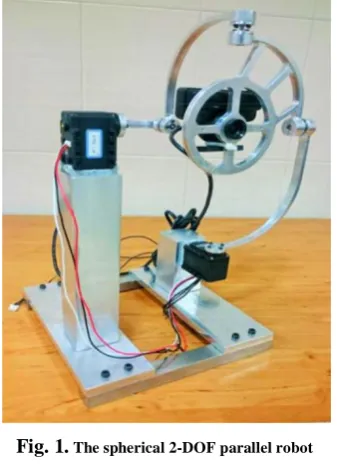
As it can be seen from Fig. 1, the under-study robot [13] is a 2-DOF spherical parallel robot, which makes this robot an appropriate choice for simulating human eye movements [14]. When two blinks occur within 3 seconds the robot will rotate 30 degrees upward, and if three blinks occur in the same interval it will result in 30 degrees downward. Moreover, when the eye moves to the left (right), the robot will move 30 degrees to the left (right). The overall insight of this project is shown in Fig. 2.In this paper, only the methods for recognition of blinking are explained. The methods for the recognition of moving eye to the left and right are the same. However, the difference between these signals and how it will be recognizedwill be explained later.
left and right eye movement will be recognized. Finally, in Section 6, an overall conclusion is proposed and some future research directions are outlined.
Fig. 1. The spherical 2-DOF parallel robot
Fig. 2. An overall insight about the whole project in which the Emotiv headset is installed on the head and transfers the data to the
2-DOF parallel robot
2. DATAACQUISITION
In this paper, for blinking recognition, as the first step, EEG signals are gathered from an Emotiv headset (Fig. 3) which gives raw data of brain activity. Emotiv headset has 16 bio-potential sensors with gold- plated connectors offer optimal positioning for accurate spatial resolution. This headset has dry sensors. The connection between these sensors and the head is by saline solution. Before putting these sensors on their place, they should be properly wetted with saline solution.
For gathering EEG signals, 10 subjects were selected with normal vision. The subjects were seated in front of a monitor located approximately 50 cm away at eye level. The subjects are asked to follow the green ball in each direction or blink when its color changed to red. Also, the tests have been done with different ball speeds in order to
evaluate the precision of the proposed algorithm with respect to speed of eye movement. After gathering data, these signals were processed in order to recognize eye movement and blinking.
Fig. 3. Emotiv headset [13]
From the first practical tests, it reveals that the effect of blinking on EEG signals in front part of the head is more impressive. Therefore, by using data which are gathered from front channels of this headset, named F7 and F8 in international 10-20 system [15], and upon processing these signals, recognition of blinking is performed, which is the subject of what follows.
3. METHODS FORBLINKINGRECOGNITION
After gathering data, these signals will be processed with different methods and blinking is recognized from EEG signals. It is obvious from Fig. 4 that effect of blinking and eye movement on EEG signals coming from the front part of scalp is considerably high with respect to other signals. Therefore, even after smoothing these signals the blinking signal is analogous.
Fig. 4. The effect of blinking on EEG signals
A. Moving Window
other noises on the signal. For this purpose, these signals are smoothed out with a rectangular method which contains a window with a specified length. In Fig. 5, it is shown that when the signal is smoothed, the part of signal in which blinking is happened has a greater amplitude than the other part of the signal.
Fig. 5. The first shows a Signal which blinking has been occurred three times and the second graph shows that signal after it has been
smoothed with a rectangular with length of 30
In order to determine blinking, in this part, a moving window with a specified length and threshold is used. The signal is scanned by the window which is shown in Fig. 4.During this process, the window moves forward through the signal. The window goes one unit ahead in each step and the mean value of these selected parts of the signal (by the window) is calculated.
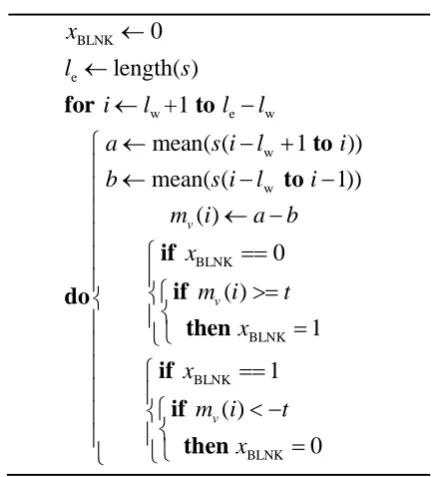
ALGORITHM 1.MOVING WINDOW
BLNK e
w e w
w w BLNK BLNK BLNK BLNK
0
length( )
+1
mean( (
1 ))
mean( (
1))
( )
0
( )
1
1
( )
0
v v vx
l
s
i
l
l
l
a
s i l
i
b
s i l
i
m i
a b
x
m i
t
x
x
m i
t
x
¬
¬
¬
-¬
- +
ì
ï ¬
-
-ï
ï
¬
-ï
==
ì
ï
ï
ï
í
ì
>=
í
í
ï
ï
î
î
=
ï
ï
ì
==
ï
ï
<
-ì
í
ï
í
ï
ï
î
=
î
î
for
to
to
to
if
if
do
then
if
if
then
In order to identify blinking in EEG signals, the mean values are compared to the threshold. If the mean value becomes larger than the threshold, then the blinking is
happened. Thus, by choosing appropriate values for length and threshold blinking could be recognized properly.
Algorithm 1 presents the general pseudo-code for the implemented Moving Window in which “
l
e” stands for the number of samples in the signal and “s” is the data which is sent by Emotiv headset. “ ” is defined in order to show when blinking is happened, when blinking is recognized “ ” changes to 1 and when it is not recognized it becomes 0 (Fig. 6-lower graph). In turn, “t” is the threshold that by repeating the tests could be found and “l
w” is the length of the window that is defined later. In Fig. 6, the result of using the above algorithm, when2
t
=
andl
w=
30
is shown.Fig. 6. The first graph shows the mean value of the signal and the second one shows the blinking when it close to 1
As mentioned earlier, “ ” is the mean value of the window. It is obvious from the algorithm that each time the window goes ahead the mean value, , is calculated and is compared with the threshold,
t
.B. Fast Fourier Transformation
The second method used in this project is the so-called Fast Fourier Transformation. In mathematics, the Discrete Fourier Transform (DFT) is a kind of transformation that deals with a finite discrete-time signal and a finite or discrete number of frequencies. DFT is equivalent to the continuous Fourier transform for signals known only at instants separated by a sample time (T), i.e., a finite sequence of data. Let f (t) be a continuous signal which is the source of the data and N samples be denoted byf [0],f
[1], …,f[k], …, f[N-1].
1 0
(
)
[ ]
N j kT kF j
w
f k e
wdt
-=
=
å
(1)FFT is an algorithm in order to compute DFT and its inverse. An FFT rapidly computes such transformations by factorizing the DFT matrix into a product of sparse (mostly zero) factors [16]. By using FFT, time is converted into frequency; therefore, the objective is finding blinking in EEG signals by converting time to frequency. As the first step, a window with “
l
e” as length is defined and in each step the window goes forward by one unit. After using FFT on the given part of signal and computing the corresponding absolute values, the mean value is computed. Then the window goes ahead and this process is repeated for all the windows.ALGORITHM 2.FASTFOURIERTRANSFORM
BLNK e
w e w
w w BLNK BLNK BLNK BLNK
0
length( )
+1
mean( (
1 ))
mean( (
1))
( )
0
( )
1
1
( )
0
v v vx
l
s
i
l
l
l
a
s i l
i
b
s i l
i
m i
a b
x
m i
t
x
x
m i
t
x
¬
¬
¬
-¬
- +
ì
ï ¬
-
-ï
ï
¬
-ï
==
ì
ï
ï
ï
í
ì
>=
í
í
ï
ï
î
î
=
ï
ï
ì
==
ï
ï
<
-ì
í
ï
í
ï
ï
î
=
î
î
for
to
to
to
if
if
do
then
if
if
then
As noted before, “s” is the data obtained from the headset, “
l
e” is the number of samples in the signal, and “sig” is the part of the signal which is selected by the window. For using FFT on the signal, a window with length of “l
w” is defined, and “x” which is FFT of “sig” is computed. Then, the absolute value of “x” which is named “x
a” is calculated. Similar to Moving Window method, the window goes ahead one unit and the mean value of the selected part of the signal is calculated which is named “f” in ALGORITHM 2 and it is compared with the threshold. If it is greater than the threshold, the blinking will occur. Fig. 7 presents the result after applying FFT on the signal shown in Fig.5 is demonstrated.Fig. 7. Result of using FFT method on EEG signals. Above graph shows the effect of using ALGORITHM 2 on the signal and the
below one shows the recognition of blinking when it gets 1
C. Wavelet Transform
The Wavelet transform is the mapping of a time signal to the time-scale joint representation which is similar to the short-time Fourier transform. The wavelet transform provides multiresolution analysis with dilated window. The high frequency analysis is performed using narrow windows and the low frequency analysis is done using wide windows [17].
Wavelet transform is easier when one uses MATLAB programming. Applying Wavelet transform on the signal in MATLAB requires just to use a simple command which is “wavedec”.
In wavedec(Signal,N,’wname’), “Signal” is the signal which is used, “wname” is the name of specific wavelet and the command decomposes the signal at levelN (N should be a positive number). In this studyN=1.
4. EXPERIMENTALRESULTS ANDDISCUSSIONS
Recognition of blinking is performed by implementing the foregoing three methods, namely, Moving Window, FFT, and Wavelet transform. However, there are other tests which have been carried out, including the effects of color changing and eye movement on EEG signals. In this part, different methods will be discussed and Correct Classification Rate (CCR) for each of them will be reported to show the accuracy of each method.
A. Moving Window
identified even when it has not happened. In addition, if the length of the window exceeds from the maximum value, blinking will not be identified. Blinking period is not constant and it may vary in different situations. For instance, in sleepiness, the blinking period becomes longer. This method can identify blinking with different periods by choosing appropriate values for the threshold and the length of the window.
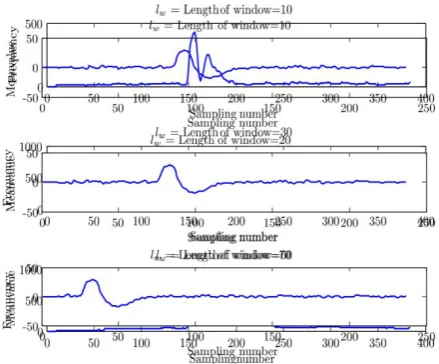
In Fig. 8, the Moving Window method with 3 different lengths of windows,
l
w= {10, 20, 70}, and with a constant threshold, 4, have been shown. It is obvious that when the length of window increases considerably, the blinking cannot be identified properly. In Table 1, the results of using different thresholds and different lengths in Moving Window Method to recognize blinking are shown. In this paper, the threshold is used her since the diffidence between the signal amplitude when blinking is happened and when it is not happened is too much.Fig. 8. Effect of using Moving Window with different length of window on a signal
TABLE 1. THE COLUMNS SHOW THE DIFFERENT LENGTHS OF THE WINDOW AND THE ROWS SHOW THE DIFFERENT THRESHOLDS WHICH ARE USED IN MOVING
WINDOW METHOD. “YES” SHOWS WHEN BLINKING IS RECOGNIZED AND “NO” REPRESENTS THE SITUATION
FOR WHICH BLINKING IS NOT RECOGNIED.
Threshold
0.5 1 5 10 15 25 30
L
e
n
g
th
10 No No Yes Yes Yes Yes No
20 No No Yes Yes Yes No No
50 Yes Yes Yes No No No No
70 Yes Yes No No No No No
100 No Yes No No No No No
As shown in Table 1, this method is sensitive to little changes of the threshold. By repeating the tests,it reveals that blinking can be well recognized when the threshold is 2 and the length of window becomes 30. In these
conditions, CCR for the Moving Window method becomes 100%.
B. Fast Fourier Transform
In FFT, after changing the signal from time to frequency, by selecting a suitable length for the window and the threshold, blinking could be readily recognized. But similar to the other methods, the length of window changes in the range of 10 to 100 and the threshold lies in the range of 100 to 250. However, repeating the test shows that the best length for the window is 20 and an appropriate threshold for determine blinking is 90. In Table 2, the results of using different length and the threshold for recognizing blinking are reported. From this table it can be inferred that the FFT method is a reliable method since it is insensitive to the defined variables. Fig. 9 illustrates how the graph of frequency changes accordingly when the length of the window changes and it becomes more complicated to recognize blinking.
TABLE 2. THE COLUMNS SHOW THE DIFFERENT LENGTHS OF THE WINDOW AND THE ROWS SHOW THE
DIFFERENT THRESHOLDS WHICH ARE USED IN FAST FOURIER TRANSFORM METHOD. “YES” SHOWS WHEN BLINKING IS RECOGNIZED AND “NO” REPRESENTS THE SITUATION FOR WHICH BLINKING IS NOT RECOGNIZED.
Threshold
50 70 90 110 150 200 250
L
e
n
g
th
10 Yes Yes No No No No No
20 Yes Yes Yes Yes Yes No No
50 No No Yes Yes Yes Yes N0
70 No No No Yes Yes Yes Yes
100 No No No Yes Yes Yes Yes
By using the FFT method with threshold of 90 and a window with the length of 20, CCR of this method becomes 100%.
C. Wavelet Transform
Wavelet transforms are a mathematical means for performing signal analysis when signal frequency varies over time. For certain classes of signals and images, wavelet analysis provides more precise information about signal data than other signal analysis techniques.
Fig. 9. Defined results using Wavelet Transform
5. RECOGNIZINGEYEMOVEMENT
Similar to the procedure performed to detect blinking, the left and right movement of the eyes can be recognized. The method is explained as follows.
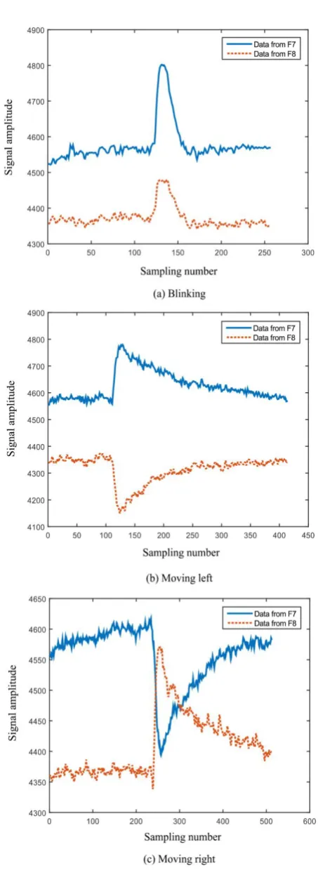
The signals of three actions of blinking, moving eyes to left and moving to right obtained from channelF7 and F8 are shown in Fig. 10(a), it can be seen, blinking has a similar effect on both channels. On the other hand, left and right movement of the eye has a reverse effect on the channels. For instance, left movement of the eyes results in a sharp increase in signal obtained from channel F7 and sharp decrease in signal obtained from channel F8 (see Fig. 10(b)). Fig. 11(c) shows the opposite effect for the right movement of the eyes.
ALGORITHM 3.MOVING WINDOW (S_1, S_2)
_ 1
mean( _1)
_ 2
mean( _ 2)
_ 1
_1
_1
_ 2
s_2
_ 2
max(
_ 1)
min(
_ 2)
>100 < 100
display('LEFT')
>100
display('BLINK
MEANvalue
s
MEANvalue
s
Signal
s
MEANvalue
Signal
MEANvalue
MAX
Signal
MIN
Signal
MAX
MIN
MAX
¬
¬
¬
-¬
-¬
¬
-if
and
then
elseif
then
')
display('right')
ì
ï
ïï
í
ï
ï
ïî
else
Fig. 10. Three different signals for blinking (a), moving left (b) and moving right (c)monitoring the signals obtained from F7 and F8 channels. After using the aforementioned methods on a given signal, for recognizing eye movement or blinking, these two signals which are gathered from two channels of the headset are compared with each other. In this way, one can easily find the action with CCR=100.
Algorithm 3 represents the pseudo-code for detecting these three actions. In this algorithm, s_1 is the signal which is gathered from F7 channel ands_2 is the one that comes from F8 channel of the Emotiv headset.
6. CONCLUSION
In this paper, spontaneous eye blinking detection was investigated based on three methods, namely, moving window, Fast Fourier transform and Wavelet transform. The challenge consisted of finding a suitable length for the window and, then, computing the mean values of the selected data in order to identify the blinking. Thus determining a suitable length for the window and also an appropriate threshold is really important. If the threshold is selected appropriately the blinking is recognized properly. By changing the threshold and the length of the window blinking was recognized which was resistant to the length of the window and the threshold. In order to obtain a suitable value for the length of the window and the threshold, several tests based on a trial and error approach were performed. Then by sending the data to the robot the blinking was simulated. As ongoing studies, more tests are being performed on recognition of blinking during eye movements. In addition, some experiments will be designed in order to detect the direction of eye movements to the up or down from EEG signals. Accomplishing the latter procedure, the obtained results will be used as the controller’s input in the movement of the Spherical 2-DOF parallel robot.
REFRENCES
[1] Dautenhahn, Kerstin, “Socially intelligent robots: dimensions of human-robot interaction,” Philosophical Transactions of the Royal Society B: Biological Sciences Vol. 362, No. 1480, pp. 679-704, 2007.
[2] Emotiv,
“EmotivEPOCUserManual”.2014.Availableinemot iv.com
[3] Carpenter, Roger HS. Movements of the eyes, 2nd rev. Pion Limited, 1988.
[4] Croft, R. J. and R. J. Barry, “Removal of ocular artifact from the EEG: A review,” Neurophysiology Clinique/Clinical Neurophysiology, Vol. 30, Issue 1, pp. 5-19, 2000.
[5] Romero, Sergio, Miguel A. Maanas and Manel J. Barbanoj, “A comparative study of automatic techniques for ocular artifact reduction in spontaneous EEG signals based on clinical target variables: a simulation case,” Computers in Biology and Medicine, Vol. 38, Issue 3, pp. 348-360, 2008.
[6] Sovierzoski, Miguel A., Fernanda IM Argoud and Fernando M. de Azevedo, “Identifying Eye Blinks in EEG Signal Analysis,” in International Conference on Information Technology and Applications in Biomedicine, ITAB 2008, IEEE, 2008.
[7] Bogacz, Rafa, Urszula Markowska-Kaczmar and Andrzej Kozik, “Blink- ing artefact recognition in EEG signal using artificial neural network,” in 4th Conference on Neural Networks and Their Applications, Zakopane, Poland, 1999.
[8] Manoilov, Plamen, “EEG eye-blinking artefacts power spectrum analysis,” in International Conference on Computer Systems and Technologies, Bulgaria, 2006.
[9] Marzano, Cristina, Fabiana Fratello, Fabio Moroni, Maria Concetta Pellicciari, Giuseppe Curcio, Michele Ferrara, Fabio Ferlazzo and Luigi De Gennaro, “Slow eye movements and subjective estimates of sleepiness predict EEG power changes during sleep deprivation,” Sleep-New York Then Westchester, Vol. 30, Issue 5, 2007.
[10] Iwasaki Masaki, Christoph Kellinghaus, Andreas V. Alexopoulos, Richard C. Burgess, Arun N. Kumar, Yanning H. Han, Hans O. Lders and R. John Leigh, “Effects of eyelid closure, blinks, and eye movements on the electroencephalogram,” Clinical Neurophysiology, Vol. 116, Issue 4, pp. 878-885, 2005.
[11] Brown, Malcolm, Michael Marmor, Eberhard Zrenner, Mitchell Brigell and Michael Bach, “ISCEV standard for clinical electro-oculography (EOG) 2006,” Documenta Ophthalmologica, Vol. 113, Issue 3, pp. 205-212, 2006.
[12] Belkacem, Abdelkader Nasreddine et al., “Classification of four eye directions from EEG signals for eye-movement-based communication systems,” Journal of Medical and Biological Engineering, Vol. 34, Issue 6, pp. 581-588, 2014. [13] Bozorgi, J., Esmaeil R., Yahyapour, I, Karimi, A.,
Tale-Masouleh M. and Yazdani M., “Design, development, dynamic analysis and control of a 2-DOF spherical parallel mechanism,” in International Conference on Robotics and Mechatronics (ICRoM), Second RSI/ISM. IEEE, 2014.
spherical parallel robot based on visual servoing controllers,” in Robotics and Mechatronics (ICRoM), Second RSI/ISM International Conference on. IEEE, 2014.
[15] Trans Cranial Technologies ldt, “10/20 System Positioning Manual” 2012.
[16] Van Loan, Charles. Computational frameworks for the fast Fourier transform, Vol. 10, Siam, 1992. [17] YunLong Sheng. The Transforms and Applications