Available Online at www.ijpret.com
36
INTERNATIONAL JOURNAL OF PURE AND
APPLIED RESEARCH IN ENGINEERING AND
TECHNOLOGY
A PATH FOR HORIZING YOUR INNOVATIVE WORK
HERRINGBONE GEAR ANALYSIS AND CALCULATION OF FORCES ACTING
ON IT IN HOT ROLLING PROCESS
MAYUUR S. SHELKE, PROF. S.D. KSHIRSAGAR
P.G. student at Department of Mechanical Engineering, Yeshwantrao Chavan College of Engineering, Nagpur, Maharashtra, India
Accepted Date: 27/02/2014 ; Published Date: 01/05/2014
\
Abstract:The steel rolling and forging is the part of metal working processes in which rolling
machines are used for constructing long and continuous sections of metal. In this paper we are discussing steel rolling use for hot metal working process. In this paper the concentration is given on analysis and the calculation of rolling load and the forces acting on the gears of steel rolling machine. After that power and torque required is calculated for the rolling load and the gear forces simultaneously which is further used for designing and analysis the gear used in gearbox of hot rolling machine.
Keywords: Hot rolling; Gear forces; Herringbone
Corresponding Author: MR. MAYUUR S. SHELKE Access Online On:
www.ijpret.com
How to Cite This Article:
Available Online at www.ijpret.com
37 INTRODUCTION
The Steel Rolling Machine is used for making angles, rods, and billets. This machine uses hot rolling process for making the required product. The Steel Rolling Machine is run by the giant 1000HP motor. Motor runs at 737 rpm. The motor is connected to the flywheel with the help of belt drive. The flywheel is further connected to reduction gearbox. The reduction gearbox reduces the speed up to 112 rpm. The reduction gearbox is connected to the transmission gearbox from which the input power is given to the system. The length of the angles is 30 to 36 meters long and 800 to 900 angles are made per shift. In this machine a frequent failure is occurred in the DOUBLE HELICAL (HERINGBONE) GEAR of transmission gear box. In this paper we have suggested the methodology for calculation of forces acting on the gear by using theory of hot rolling. In this paper the analysis is done using solid works. For obtaining calculations we have calculated the motor power available at the input. For actual power requirement we have consider the HOT ROLLING THEORY and calculated the required power and torque for rolling process.
2. GEAR FORCE CALCULATIONS
2.1 Gear Profile Calculation:
• Material of Gear – EN9 (BS 970)
• Helix angle ψ – 26.6 degree
• Pressure angle Ø – 20 degree
• No. of Teeth – 22 teeth 2(D.P.)
• Thickness of teeth – 27 mm
2.2 Power Available at Input:
Motor power (P) = 745.69E3 watt
Efficiency of Gearbox = 85% (for Double Helical Gear)
Power at Input = 633.83E3 watt
Speed (N) = 112 rpm
Available Online at www.ijpret.com
38
(T) = P*60/2Πn
= 633.83e3*60/2π112 Torque = 54.04 KNm
2.4 Force Calculations:
Pitch Circle Dia = 290mm
Pitch Circle Redius = 290/2
= 145mm
=0.145m
Motor force (Fm) = Torque/Distance
= 54041.34/0.145
Fm = 372698.93 N
2.5 Forces acting on Gear:
Compressive force (Fc) = Fm *sin Ø
Ø=Pressure angle
=372698.93*sin(20 ̊)
Ø=20 ̊
Fc = 127470.54 N
Tangential force (Ft) = Fm*cos Ø
= 372698.93*cos (20 ̊)
Ft = 350222.43N
Force acting Normal to the Teeth (Fn)
= Fm*cos ψ ψ= Helix angle
Available Online at www.ijpret.com
39
Fn = 333541.07N
Note: We are not considering Axial Thrust because of opposite angle of Helix in case of Double
Helical Gear.
3. ROLLING LOAD CALCULATIONS
3.1 Properties of Material to be used for Hot Rolling:
Material – A36 Mild Steel
UTS – 400 Mpa
Yield Strength – 250 Mpa
Elongation – 20%
Carbon – 0.26
Density – 7800 kg/m^3
Poisons ratio – 0.26
Shear Modulus – 79.3 Gpa.
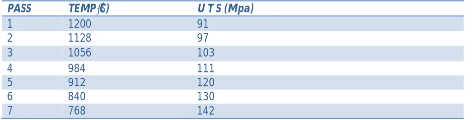
TABLE 1: Effect of Temp on UTS
PASS TEMP(̊C) U T S (Mpa)
1 1200 91
2 1128 97
3 1056 103
4 984 111
5 912 120
6 840 130
Available Online at www.ijpret.com
40
Graph 1: Effect of Temp on Strength
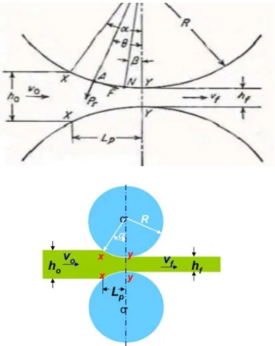
3.2 Analysis of Rolling Load (P) using Hot Rolling Theory:
Where: P = rolling load
σo = mean stress between entrance and exit
Q = complex function of reduction in thickness
b = width of material
R = radius of the roller
Δh= difference between input and output thickness
Now,
Mean Thickness: h
Where:
ho = input thickness 1200 1128 1056 984 912 840 800 850 900 950 1000 1050 1100 1150 1200 1250
80 90 100 110 120 130 140 150
T
E
M
P
UTS IN MPA
Available Online at www.ijpret.com
41
hf = output thickness
h = mean thickness
Complex funcn of reduction in thickness: Q
Where:
Lp = Projected length of arc of contact
Lp = √ ℎ
µ = coefficient of friction = 0.3
R = radius of roller = 165 mm
Mean stress:
σO= (σ entrance + σ exit) / 2
Maximum possible reduction in thickness:
(Δh) max = µ2R
Available Online at www.ijpret.com
42
Fig: 2 Input and Output parameters for Rolling 2
TABLE 2: Rolling Load (P)
PASS Ho
mm
Hf mm
Δh
mm
h Mm σO mpa σ in
mpa
σ out
mpa
Q P (KN)
1 100 85 15 92.5 94 91 97 0.16 507.03
2 85 70 15 77.5 100 97 103 0.19 547.79
3 70 55 15 62.5 107 103 111 0.23 598.39
4 55 40
15 47.5 115.5 111 120 0.31 673.50
5 40 25 15 32.5 125 120 130 0.45 785.21
Available Online at www.ijpret.com
43
The ratio of moment of arm to the projected length = λ
λ = a / LP λ = 0.5 (for hot rolling)
a = 0.5*49.74
a = 24.87 mm
Where: a - Effective moment arm, Lp - Projected length of arc of contact
3.3 Torque required for Hot Rolling:
MT = 2Pa
Torque = 53.02 kn-m
3.4 Power required for Hot Rolling:
Work done = Power =W
W = 4πaPN, Power = 621.96Kw
4. ANALYSIS
The values obtain from the above calculation are taken into consideration for the analysis of the existing gear of the transmission gearbox. The analysis is done using solid works simulation express. For this purpose the factor of safety is consider as 3 which is best suitable for the design of herringbone gear. From the results we can say that at the certain areas the factor of safety is below safe limit. This area is indicate by the red colour. The von mises plot shows the maximum value 384.3 Mpa which is below the yield limit of 415 Mpa but since the FOS plot is not in range the gear need to make certain geometry changes in particular areas. Taking the material of higher strength and geometry change in certain area can solve the problem.
Available Online at www.ijpret.com
44
Fig.: 4 FOS plot.
5. CONCLUSION
From above calculations and analysis we can say that the torque obtain for rotating the transmission gearbox of rolling machine and the torque required for the rolling of metal are approximately same. The calculation obtain for the power required to operate the transmission gear box and the power required for the rolling of metal is found out to be approximately same. Using these calculations the analysis is done on the gear and it is found that in certain sections the factor of safety is below safe limit. There for changes in geometry or change in the material is suggested to solve the problem.
REFERENCES
1. Failure diagnosis of high speed gear (Fang Wang- Sch. of Autom. Sci. & Electr. Eng., Beihang Univ., Beijing, China, Shaoping Wang)IEEE-Aug.2011, Print ISBN:978-1-4244-8451-5, Page(s):878 - 883
2. Time-frequent feature analysis of gearbox vibration with shaft angle error (Xin Weidong Sch. of Energy, Power & Mech. Eng., North China Electr. Power Univ., Beijing, China, Liu Yibing ; Li Zhuang. IEEE-July 2012, Print ISBN: 978-1-4673-2581-3, Pages 5353 – 5356
3. Modal analysis of the helical gear of the increasing gear box for wind generator (Zhou Yucheng Sch. of Mech. & Electron. Eng., Tianjin Polytech. Univ., Tianjin, China, Wu Baolin.) IEEE-May 2010, Print ISBN:978-1-4244-7653-4, Page(s):198 - 201
Available Online at www.ijpret.com
45
5. Fatigue failure of a helical gear in a gearbox. (Osman Asi,Department of Mechanical Engineering, Usak Engineering Faculty, Afyon Kocatepe University, 64300 Usak, Turkey.) Elsevier-Volume 13, Issue 7, October 2006, Pages 1116–1125
6. Gear Impacts And Idle Gear Noise: Experimental Study And Non Linear Dynamic Model. - Elsevier (Jean-Luc DION, Sylvie LE MOYNE, Gael CHEVALLIER.
7. Classification of gear faults using cumulants and the radial basis function network. - Science-direct (Lai Wuxing, Peter W. Tse, Zhang Guicai, Shi Tielin)
8. Failure Analysis of Gears-Shafts. (Rexnord Industries, LLC, Gear Group.)
9. Shigley's Mechanical Engineering Design 9 Edition (Authored By: J. Keith Nisbett, Richard G. Budynas.) Tata McGraw - Hill Education (2011).
10.Gear Design Handbook by Gitin M. Maitra.
11.Edwards, L. and Endean, M. Manufacturing with materials 1990, Butterworth Heinemann, ISBN 0-7506-2754-9.
12.Dieter, G.E., Mechanical metallurgy, 1988, SI metric edition, McGraw-Hill, ISBN 0-07-100406-8