Doctoral School in Materials Science and Engineering
Materials Development for the Fabrication of
Metal Supported-Solid Oxide Fuel Cells by
Co-sintering
Pradnyesh Satardekar
Advisor: Prof. Vincenzo M. Sglavo
September 2014
X
X
V
II
cycl
Materials Development for the Fabrication
of Metal Supported-Solid Oxide Fuel Cells
by Co-sintering
Pradnyesh Satardekar
E-mail: [email protected]
Approved by: Ph.D. Commission:
Prof. Vincenzo Maria Sglavo, Prof. Flavio Deflorian
Advisor Department of Industrial
Department of Industrial Engineering
Engineering University of Trento, Italy. University of Trento, Italy.
Prof. Peter Leisner J ̈nk ̈ping University- School of Engineering, Gjuterigatan 5, Sweden.
Dr. Stefano Pandini Department of Mechanical and Industrial Engineering University of Brescia, Italy.
University of Trento,
Department of Materials Science and Engineering
University of Trento – Department of Materials Science and Industrial Engineering
Doctoral Thesis
Pradnyesh Satardekar - 2014
Abstract
Solid Oxide Fuel Cell (SOFC) is an upcoming technology seen with great expectations for the production of electrical energy with good efficiency and minimal environmental impact. Successful commercialization of SOFCs has however been hindered despite the optimistic promises made by some developers. This slackened commercialization of SOFCs technology is mainly due to the high cost associated with SOFC production and its limited long term stability. The long term stability of conventional Anode Supported-Solid Oxide Fuel Cell (AS-SOFC) with Ni based anode is tested by its limited tolerance towards redox cycling and rapid thermal cycling.
The introduction of new generation SOFC, the so called Metal Supported- Solid Oxide Fuel Cell (MS-SOFC) has shown to overcome the drawbacks associated with the conventional AS-SOFC. Thus, MS-SOFC is looked upon as the potential candidate for the rapid commercialization of SOFC technology. In MS-SOFC design, the cell is supported on a porous metal substrate instead of expensive and non-reliable anode as in AS-SOFC. In this design the thickness of the functional layers (anode, cathode and electrolyte) is kept thin as possible (in the order of 10-50m) just necessary for electrochemical activities while the support being provided by the metal substrate.
Although MS-SOFC can be fabricated by different routes, co-sintering of metal/anode/electrolyte multilayers in non-oxidizing atmosphere at high temperatures (1300 to 1400oC) is the most promising as far cost efficiency and industrial scale up is concerned. The cathode is usually applied after high temperature processes and sintered in situ during operation in this route. This fabrication approach however has some drawbacks associated with it. This work is basically on the development of materials and optimization of the multilayer design for the production of MS-SOFC by cost-effective co-sintering approach. YSZ (Y2O3 stabilized ZrO2), Ni-YSZ cermet, and
ferritic stainless steel are considered for the electrolyte, anode and the support respectively. The anode and electrolyte were modified with the help of suitable dopants and the multilayer design was also altered in order to facilitate the co-sintering, preventing or reducing the generally encountered issues in this fabrication route.
current work, the effect of Al doping on Ni-YSZ anode sintering in Metal Supported-Solid Oxide Fuel Cell (MS-SOFC) was studied. It was found that, the addition of Al into the anode accounts for a finer microstructure if compared to undoped Ni-YSZ anode material. The electrical conductivity of the Al-doped anode was also found to increase considerabely and such result may be attributed to the fine microstructure caused by the segragation of Al2O3 formed during the
course of sintering on the grain boundaries of both Ni and YSZ, thus inhibiting the sintering. 5wt% Al-doped NiO used for Ni-YSZ anode material gave the finest microstucture and the highest electrical conductivity at room temperature although it showed the lowest bulk density. Overall, Al-doped Ni-YSZ anode material was found to be a suitable material for the anode in MS-SOFC produced by co-sintering. The modification of the reduction kinetic of NiO and the interaction between the anode and steel during the fabrication of Metal Supported Solid Oxide Fuel Cells (MS-SOFC) is also studied in the present work. With the aim to limit NiO reduction under inert atmosphere at high temperature, doping elements such as Al and Ce were considered for NiO powders modification and anode production. In order to simulate the reactions at the metal/anode interface, NiO/YSZ/steel composites were prepared with pure and Al-doped NiO. A sudden volume expansion above 10000C followed by substantial shrinkage above 12000C was observed for the composites when sintered in Ar at 14000C. Such volume expansion can be related to the oxidation of steel due to the RedOx reaction between NiO and steel. Moreover, it was found that the volume expansion, i.e. the steel oxidation, can be minimized to a good extent when Al-doped NiO is used. Hence it is proposed that Al-doped NiO is a promising candidate material to be used for anodes in high temperature sintering of MS-SOFC.
for investigation, YSZ/(Al-NiO)-YSZ/LDC-steel/steel multilayer design was found to be a good compromise so as to give a half-cell, with good bonding between the layers, which is camber free, and with moderate interdiffusion of elements between the substrate and the anode. It was however found in all the designs that complete densification of YSZ electrolyte could not be obtained.
In order to address the issue of limited densification of YSZ electrolyte during co-sintering, Fe was considered for doping YSZ. A comparative study was done on Fe doped YSZ samples for sintering in air and argon atmosphere, with the aim to analyze the effect of Fe as sintering aid under MS-SOFC fabrication by co-sintering conditions. Samples showed enhanced densification with increasing Fe concentration in both the sintering atmospheres thus concluding that Fe can be used as a sintering aid for YSZ even in argon. The samples sintered in argon atmosphere were however characterized by larger lattice parameter, density and grain size. The increase in lattice parameter can be attributed to the oxygen vacancies generated under low p(O2) in argon atmosphere. The microstructural
1. Introduction ... 1
2. Theoretical background ... 6
2.1. Fuel Cells v/s SOFCs ... 6
2.2. SOFCs basic principles ... 10
2.3. Basic SOFC designs ... 15
2.3.1. Tubular design... 15
2.3.2. Planar design... 16
2.4. Advent and advantages of MS-SOFC ... 19
2.5. Materials for MS-SOFC ... 22
2.5.1. Choice of substrate ... 22
2.5.2. Electrolyte Materials ... 29
2.5.3. Cathode Materials ... 36
2.5.4. Anode Material ... 38
2.6. Fabrication of MS-SOFC ... 41
2.6.1. Fabrication by non-co-sintering routes ... 41
2.6.2. Fabrication by co-sintering routes ... 45
2.7. Powder consolidation by tape casting for SOFCs ... 49
2.8. De-binding and sintering ... 54
2.8.1. Driving force for sintering ... 54
2.8.2. Matter transport ... 55
2.8.3. Mechanism of sintering ... 55
2.9. Constrained sintering ... 57
2.9.1. Constrained sintering of thin film on a rigid substrate ... 58
2.9.2. Constrained sintering of multilayers ... 60
3. Experimental procedure and results ... 62
3.1. General experimental methods and techniques ... 62
3.2.1. Introduction and aim of the analysis ... 66
3.2.2. Materials and methods ... 66
3.2.3. Results and Discussion... 69
3.2.4. Conclusion ... 79
3.3. Investigation of anode/steel interface and dopant effect ... 80
3.3.1. Introduction and aim of the analysis ... 80
3.3.2. Materials and methods ... 81
3.3.3. Results and discussion ... 83
3.3.4. Conclusion ... 91
3.4. Optimization of sintering conditions and multilayer design ... 92
3.4.1. Introduction and aim of the analysis ... 92
3.4.2. Materials and methods ... 93
3.4.3. Results and discussion ... 97
3.4.4. Conclusion ... 108
3.5. Effect of Fe dopant on YSZ electrolyte ... 110
3.5.1. Introduction and aim of the analysis ... 110
3.5.2. Materials and methods ... 111
3.5.3. Results and discussion ... 113
3.5.4. Conclusion ... 123
3.6. General Conclusion ... 125
Bibliography ... 128
Curriculum Vitae... 145
1. Introduction
Combustion of fossil fuels has been the primary route for generation of electricity since past 100 years. This route is however associated with limitations such as intrinsically low conversion efficiency, and emission of carbon dioxide and other air pollutants affecting the environment. The increasing demand for energy, exhaustion of fossil fuel reserves, and the growing concern about the environment has implemented the need to generate electricity more efficiently, and with minimal impact on environment. The use of fuel cell to generate electricity is a very promising approach to overcome the above mentioned issues. Fuel cell is an energy conversion device to electrochemically convert directly the chemical energy of the fuel such as hydrogen, methanol, ethanol, natural gas and hydrocarbons to electricity, and hence, fuel cells offer higher conversion efficiency than conventional energy conversion technologies such as internal combustion engine (ICE).
Among the various types of fuel cells, solid oxide fuel cells (SOFCs) are considered to be most promising, as they let internal reforming, promote fast kinetics with non-precious catalyst materials, and allow the use of various fuels, all due to its high operating temperature. The compactness, modularity, and durability SOFCs find in particular applications in stationary, distributed power generation, a niche market in which conventional heat engines find it hard to compete. These unique advantages of SOFCs have retained the interest of researchers and developers worldwide for their commercialization since last few decades.
2
Each design has its own advantages and disadvantages, but planar design has however gained more attention as higher power densities can be obtained. YSZ (Y2O3 stabilized ZrO2) has been the preferred
electrolyte material for SOFC due to its pure ionic conducting behavior and its excellent stability under SOFC operating conditions. Ni/YSZ cermet has been the most widely used anode material, and LSM (Sr doped LaMnO3) and LSCF (Lanthanum strontium cobaltite
ferrite) are the standard cathode materials used in SOFCs.
Commercialization of SOFC technology is however been slackened due to the two major obstacles, i.e. product cost and system reliability. High cost of materials and cell processing is still hindering the commercial deployment of SOFCs. Furthermore, the long-term stability of the conventional anode supported SOFC (AS-SOFC) with Ni base anode is challenged by its limited redox stability. One of the strategies to crack these issues is the introduction of metal support in cell’s architecture.
relatively cheap but also because of its high temperature oxidation resistance and thermal expansion coefficient (TEC) which closely matches that of interconnects.
4
steel and of Ni coarsening. The reason is that the oxygen partial pressure in the furnace can be controlled by the release of O2 due to
NiO reduction and, therefore, it does not need a direct interface between the two phases. Nevertheless, the high temperature effect on steel and anode can be reduced by decreasing the electrolyte sintering temperature by using low-temperature processes such as Pulsed Laser Deposition (PLD) and Vacuum Plasma Spray (VPS). Another approach is the infiltration of Ni catalyst into the porous metal/porous YSZ/dense YSZ multilayer structure after high temperature processing. In any case such low temperature processes are multistep and expensive and therefore not suitable for production on an industrial scale. Therefore, the co-sintering of multilayer still remains an attractive choice.
In this work, cost-effective co-sintering route has been considered for the fabrication of planner MS-SOFC.YSZ, Ni-YSZ cermet, and ferritic stainless steel are considered for the electrolyte, anode and the support respectively. The main aim of this work is to develop materials and to optimize the processing route in order to reduce or prevent the abovementioned problems during co-sintering for MS-SOFC.
about the optimization of sintering condition, and multilayer design produced by tape casting for the fabrication of MS-SOFC. The last topic is on sintering of Fedoped YSZ electrolyte under non-oxidizing atmosphere for the MS-SOFC. The final section of this thesis is the general conclusion where the entire work is concluded in general.
Some work related to the deposition of protective coating on the porous stainless steel substrate was also done during this PhD period. This work is however not reported in this thesis as it is subjected to a patent at Italian Patent and Trademark Office (IPTO) since August, 2013.
This PhD work was co-funded by SOFCpower SpA in the frame of RAMSES project.
6
2. Theoretical background
2.1. Fuel Cells v/s SOFCs
Fuel cells are electrochemical devices which converts the chemical energy in the fuel directly into electrical energy with high efficiency and in environmental friendly manner. Power generation by fuel cells unlike the conventional modes of generating electricity does not involve intermediate steps of producing heat and mechanical work. Thus, fuel cells are not limited by the thermodynamic limitations of heat engines such as Carnot efficiency and therefore have inherently higher efficiency. Higher efficiency also means lower CO2
emission per unit production of electricity when hydrocarbons are used as fuel. In a fuel cell the reaction between fuel and oxidant takes place electrochemically as a result of which there is no combustion of fuel; hence electricity is generated with minimal pollutants. In addition, fuel cells have good size flexibility i.e. they can be scaled up to systems ranging from few watts to megawatts theoretically without any loss in efficiency. Another advantage is that, quiet and vibration-free operation of fuel cells also eliminates the noise usually associated with conventional power generation systems [1] [2] [3].
Although fuel cells are promising, they are associated with major practical issues which involve materials and manufacturing cost. In addition, there these two fundamental technical issues; the slow reaction rate leading to low currents and power, and that hydrogen which is the most preferred fuel is not readily available [4]
fuel cells (AFC), phosphoric acid fuel cell (PAFC), molten carbonate fuel cells (MCFC), and solid oxide fuel cells (SOFC).Overview of different types of fuel cells and their features are given in Table 1.
Features PEFC AFC PAFC MCFC SOFC
Electrolyte Polymeric membrane Potassium hydroxide Phosphoric acid Carbonate
salt mixture Ceramic
Catalyst Platinum Platinum Platinum Electrode material
Electrode material Operating
T(oC) 50-100 70-250 150-200 600-700 400-1000
Charge
Carrier H+ OH- H+ CO32- O
2-External Reformer for
HC fuels
Yes Yes Yes No, for some fuels No, for some fuels and cell design External shift conversion of CO to H2
Yes, plus removal of CO traces required Yes, plus removal CO and CO2 required
Yes No No
Table 1. Overview of different types of fuel cells [2][5].
Each of the above mentioned fuel cells have different advantages and preferential application field depending on the operating temperature and the fuel used.
As indicated by the name itself, in SOFC the electrolyte is a solid, oxygen ion conducting metal oxide, usually Y2O3 stabilized
ZrO2. The gas tight electrolyte is sandwiched between porous anode
8
cathode is a perovskite such as Sr doped LaMnO3.The operating
temperature of SOFC is between 400-1000oC.Due to the solid electrolyte, SOFCs possess advantages over other type of fuel cells consisting of non-solid electrolyte such as, they can be fabricated in various shapes like planner, tubular and monolithic. The solid electrolyte in SOFC also allows to precisely engineer the triple phase boundaries and there is no problem of electrolyte flooding into the electrodes. Moreover, since the unit cell is constructed of solid ceramics there are no corrosion issues.
The most important advantages of SOFC over other fuel cells are associated with their higher operating temperatures typically in the range of 600-1000oC. Higher temperature means that there is no need of valuable metal catalyst. Also, SOFC can be used with variety of fuel ranging from hydrogen to CO to hydrocarbon (both in liquid and gaseous state). The higher operating temperatures efficiently activate the process of reforming and electrochemical oxidation of hydrocarbon fuel in the presence of catalyst. The reforming of hydrocarbon fuels which is highly endothermic can be achieved internally on-cell from the high quality heat generated by exothermic electrochemical oxidation of fuel, giving H2 and CO. CO
with H2O shifts to H2 and CO2. Thus, CO acts as a fuel in SOFC
turbine can be added to these above mentioned hybrid systems in order to be even more efficient. Applications and integration of SOFC with other systems for power generation has been extensively reviewed in [6] [7] [8].
Unfortunately the major drawbacks of SOFCs are also associated with their higher operating temperatures. Due the high operating temperature the material selection for the core of SOFC system is limited only to those which can withstand such temperatures. Therefore organic materials and low temperature metal alloys cannot be used. The material selection remains limited to ceramics, metal/ceramic composites and high temperature alloys. Another problem is that the thermal expansion coefficients (TEC) of the components in particular anode, electrolyte, cathode, sealing and interconnect have to be carefully matched. The mismatch in TEC of these components often destroys the cell during temperature variations for production, operation, and thermal cycles from room temperature to operating temperature. Finally the fragile nature of ceramics in SOFC makes them intolerable to stresses when used in stacks under real operating conditions. These stresses arise from thermal shocks, mechanical solicitations or RedOx cycles. Moreover, the compressive sealing which requires high applied pressure cannot be used.
10
2.2. SOFCs basic principles
In a Solid Oxide Fuel Cell, the electrical power is generated by the electrochemical reaction between fuel and oxygen. The driving force is the global cell reaction free energy change; ∆G. SOFCs consists of 3 fundamental layers, a central gas tight dense electrolyte layer and the porous anode and cathode layers on either side of the electrolyte. The basic requirement of electrolyte material is that it should be good oxygen ion conductor and insulating towards electrons. The working principle of SOFC is depicted in Fig.1. Fuel such as H2 is fed in the anode side and oxidant i.e. air or O2 is
supplied in the cathode side. Oxygen ions are formed at the cathode by reduction of oxygen. These oxygen ions, driven by the difference in oxygen chemical potential between fuel and air compartment, are transported through the electrolyte by vacancies migration mechanism to the anode side. On the anode side the fuel is oxidized by oxygen ions by mechanism which can involve series of adsorption and dissociation steps over the catalyst surface, generating electrons. Since the electrolyte is insulating towards electrons, the electrons are forced to flow through external circuit between anode and cathode to balance the internal ionic current.
The operating temperature of SOFC which is usually between 400oC -1000oC is determined by the oxygen ion conductivity of the electrolyte material and also the thickness of this electrolyte layer.
When hydrogen is used as fuel, the half-cell reactions occurring at the electrodes are:
Anode: H2 + O2- H2O + 2e
-Cathode: ½ O2 + 2e- O
H2 + ½ O2 H2O
Fig.1. Operating principle in solid oxide fuel cell with H2 as fuel and O2 as oxidant.
For a fuel cell, the performance is evaluated as the voltage output at a given current flow. The current and the DC power output are usually normalized as current density and power density per unit surface of the electrolyte, respectively.
At equilibrium the cell voltage is given by the Nernst equation:
(
⁄
)
12
Where is the standard Gibbs free energy change for the hydrogen oxidation, is the standard enthalpy change and ∆So
is the standard entropy change.
The Nernst potential, E, gives the ideal open circuit cell potential. This potential sets the upper limit or the maximum performance achievable by fuel cell. For the overall cell reaction the potential increases with an increase in partial pressure (concentration) of reactants and decrease in partial pressure of products.
Under operating condition when the current is flowing through the cell, the actual cell potential is lower than its ideal potential due to several types of irreversible loses, namely, activation, ohmic, and concentration polarization. A typical voltage-current density plot is shown in Fig.2.
Activation polarization (ηact) stem from the activation energy
of the electrochemical reactions at the electrodes i.e. the charge transfer processes, and depends on the nature of electrode-electrolyte interfaces. The charge transfer reactions are thought to occur within a limited distance from the electrolyte/electrode interfaces (in the order of 10 µm) at zones known as triple phase boundaries (TPB). TPB are the regions where the three phases involved in the reaction i.e. electrolyte, electrode catalyst and the gas meet, and are the active points for the charge transfer reaction to occur. TPB length can be increased by making the electrode microstructure finer and thus the activation losses can be reduced.
The ohmic polarization (ηohm) is the voltage loss due to
ohmic resistances. The parameters contributing to the overall ohmic loss are ionic conductivity of electrolyte, ionic and electronic conductivity of the two electrodes, thickness of the electrolyte and the electrodes, and the ohmic resistances associated with the interfaces. The main contribution to the ohmic polarization is through the electrolyte. A high ionic conductivity and small electrolyte thicknesses are the desired characteristics of the solid electrolyte to minimize the ohmic contribution. On the other hand, ohmic contribution from the electrodes depends on the relative composition of the two phases (in composite electrodes), amount of porosity and microstructure, in particular the geometry of the particle to particle contact. Finally the contact resistance associated to electrode-current collectors interfaces must also be considered in SOFC stack.
The concentration polarization (ηconc) contribution to the
14
polarization are electrode porosity, pore size and pore morphology (which affects the tortuosity factor) and electrode thickness (thinner the electrode, the lower is the concentration polarization). At low current density the concentration polarization is negligible, however under practical conditions (high current density and low fuel and air concentration), they contribute significantly for the loss in cell potential.
2.3. Basic SOFC designs
The electrolyte and the two electrodes in a SOFC can be configured in different geometrical configurations giving several designs. Planar and tubular are the two basic SOFC designs which have been extensively studied and developed since the last few decades. These units of SOFCs are connected electrically to obtain the desired power output. Reference [10] summarizes world-wide efforts in the field of SOFC, presenting an overview of the main SOFC design and the main developers’ active in this field.
2.3.1. Tubular design
Tubular SOFCs can be of tubes with large diameter (>15mm), or of tubes with much smaller diameter (< 5mm), the so called microtubular cells. In order to increase the power density and to allow the easier deposition of the electrodes these tubes may be flat and joined together (Fig.3.). Siemens Westinghouse Power Corporation or SWPC have been the major developers of tubular SOFC since late 1970s. The design illustrated by SWPC is given in Fig.3.The porous tube composed of lanthanum doped manganite with one end closed is fabricated by extrusion and sintering. Dense YSZ electrolyte, porous Ni-YSZ anode and doped lanthanum chromite interconnects are then deposited in the form of thin layers by atmospheric plasma spraying.
16
generating electricity. The biggest plus point associated with the tubular SOFC design is that it does not require high temperature seals to prevent the mixing of the fuel and the oxidant. This in fact is the reason why stable performance is achieved for SOFC with tubular concept over a large period of time (several years). However, as a result of long path for electrical power through each cell, and the large void within the cell structure, low power densities are obtained for tubular SOFCs which is its biggest setback.
Fig.3. Tubular solid oxide fuel cell design and alternate geometries investigated by Siemens [3]
2.3.2. Planar design
SOFC can be, electrolyte-supported, electrode-supported or metal-supported. Furthermore, the flat cells can be circular in shape where the fuel is supplied through the central hole, or it can be in the square or rectangular shape fed from the sides. The variants of planar SOFC are illustrated in Fig.4. The manufacturing methods of SOFC with
Fig.4. Planar solid oxide fuel cells with rectangular and circular shapes showing the modes of fuel and oxidant supply [3][10].
18
2.4. Advent and advantages of
MS-SOFC
SOFC technology has been thoroughly investigated by companies and researchers world-wide for many decades. Two generations of planer SOFCs with significant improvement in performance have been explored; first the electrolyte-supported SOFC (ES-SOFC) and then the electrode-supported SOFC. However, successful commercialization of traditional SOFC technology is prohibited for many reasons; high cost associated with raw material, unreliable cell sealing, limited tolerance of cell to the stresses due to rapid thermal transients, mechanical shocks, or oxidation of anode and, manufacturing issues related to high-yield production of large, complex ceramic parts . The further refinement of the SOFC design has led to the advent of 3rd generation SOFC, the so called ‘Metal-supported SOFC (MS-SOFC). MS-SOFC design is the recently introduced concept with the potential to overcome the above mentioned problems, thus making itself a promising candidate for commercialization [11]. The comparison of different generations of planner SOFCs is illustrated in the Fig.5.
20
In the case of ES-SOFC the mechanical support for the thin electrode layers (~50µm) is provided by comparatively thicker electrolyte layer (>150µm), typically Y2O3 stabilized ZrO2 (YSZ) .In a
SOFC, the main contribution to the ohmic polarization is through electrolyte. For ES-SOFC the ohmic contribution is large due to the high electrolyte resistivity. The electrolyte resistivity can be reduced by increasing the operating temperature as the conductivity of typical SOFC electrolyte display Arrhenius-dependence on temperature. Therefore, these cells are operated at high temperature of ~1000oC to achieve sufficiently low electrolyte resistivity (~20 Ω cm).Another way of reducing the ohmic contribution due to the electrolyte at lower temperature is by simply making it thinner. For instance, at 800oC the resistivity of YSZ is about 50 Ω cm giving the area specific resistance (electrolyte contribution) of about 0.75 Ω cm2
when 150 µm thick YSZ electrolyte is used. This is a very high value with the result that the power density is rather low at temperatures below about 950oC. However, when the thickness of electrolyte is reduced to, say 10 µm, the area specific resistance of electrolyte is only 0.05 Ω cm2
challenges (it is difficult to obtain fully sintered YSZ electrolyte without oversintering the Sr doped LaMnO3 i.e. LSM cathode) associated with
cathode-supported SOFC.
In the electrolyte-supported, and the electrode-supported SOFC the mechanical support is the expensive and brittle, ceramic or cermet material. In contrast, in the case of metal supported design the electrode and the electrolyte layers are supported on the comparatively inexpensive and robust, porous metal substrate. The ceramic layers only as thick (under processing constraints) as necessary for the electrochemical activities are applied directly to the metal substrate. The metallic support can be either on the cathode side or anode side, but mostly latter is preferred due to manufacturability and stability issues. Although most developers of MS-SOFC use planner support, tubular supports are also gaining popularity.
MS-SOFC design thus promises advantages over the conventional ceramic/cermet supported cells such as low materials cost, ruggedness and abuse tolerance, good manufacturability and operational advanteges.MS-SOFC design allows the use of conventional metal joining techniques, such as welding or brazing for sealing during assemblage of cells. Good thermal conductivity and ductility of metallic substrate, which may both improve thermal shock resistance, and lower the internal temperature gradient, allows the quicker startup. This, along with mechanical ruggedness of MS-SOFC is advantageous in APU application where the cell or stack is likely to experience shock, vibration, or mechanical loading. Another advantage is the redox cycling tolerance which allows the cells to cool down without the need of blanketing, interruption in fuel supply, and catalyst oxidation at high current density.
22
2.5. Materials for MS-SOFC
2.5.1. Choice of substrate
The alloy/metal substrate used in MS-SOFC should satisfy the requirements which are similar to that of alloy interconnects used in SOFC. The basic difference between substrate and the interconnect material is that later should be gas tight and, former should be porous (~ 30-35 vol% porosity) to allow the mass transport. Besides, interconnects are exposed to dual atmosphere i.e. cathode and anode atmosphere whereas, the metal substrate is exposed to one the two atmospheres depending on the side which it is attached. The requirements for alloy/metal to use as substrate are as follows. The alloy should have high electrical conductivity, high mechanical strength and low oxidation rate. The low resistivity of the protective oxide scales formed by the alloy during operation is also desired. Furthermore, thermal expansion coefficients (TEC) of the alloy should fairly match with that of other cell components from room temperature up to operating temperature. Finally, the substrate should also have chemical compatibility with components of cell in contact during operation, and cost factor should also be considered.
electrolyte materials, they are cheap, have good oxidation resistance, and their forming and production technology is well established. One drawback of FSS is that they possess low mechanical strength. Ni and Ni-Fe supports are studied as potential support candidates, as their well-developed manufacturing technology relieves considerably the cell fabrication limitations. Drawbacks of these materials are
Fig.6. Schematic phase diagram for Cr-Ni-Fe system [13] that, in addition to their poor redox resistance, low oxidation resistance, and relatively low mechanical strength, they are susceptible to coking under lower steam to CH4 ratio and are
expensive. The issues associated with Ni-Cr containing alloys are that they have TEC lager than most of the electrolyte and they are expensive.
24
FSS candidates, two additional parameters should be considered, namely particle size and the oxidation rate constant of the alloy.
Alloys TECa( 10
-6K-1)
Oxidation resistance
Mechanical strength
Manufact
urability Cost
Cr based 11.0-12.5 Good High Difficult Very
expensive
Ferritic SS 11.5-14.0 Good Low Fairly
readily Cheap
Austenitic
SS 18.0-20.0 Good Fairly high Readily Cheap Fe based
supper alloy 15.0-20.0 Good High Readily
Fairly cheap
Ni based
super alloys 14.0-19.0 Good High Readily Expensive
Ni 16.0-17.0 Low Low Readily Expensive
NI-Fe 13.0-14.0 Low Low Readily Fairly
expensive
Table 2. Comparison of key properties of selected alloys [3] .
a average between 25 and 900oC
Note that TEC of electrolytes (YSZ, CGO, LSGM= 10-12 x 10-6K-1)
(a) Effect of Alloy particle size
have to be deposited on the metal substrate, alloy is desired to have smooth surface with small pores. In this case small alloy particles are preferred.
The performance and stability of ferritic alloys are also determined by their particle size. The particle size of ferritic alloy should be large enough to form the continuous protective Cr2O3 scale
on the surface, while still retaining sufficient Cr in the bulk.
Fig.7. gives the estimate of the particle size for alloy containing 22 wt% Cr for ideal support microstructure consisting of spherical spheres. The critical thickness of Cr2O3 scale is considered
to be around 1µ which is assumed to fully cover the sphere surface. It is assumed that the thickness of neck between metal particles should be at least between 4-5µ to avoid complete corrosion of these conducting paths. Density of the Cr2O3 scale is used to calculate the
Cr concentration to form the scale and thus the Cr remaining in the bulk.
Fig.7. Evolution of Cr concentration (in wt%) in the bulk and in the oxide scale (thickness:1 and 1.5 µ) as a function of particle size for
26
It can be seen from Fig.7. that it is not possible for the alloy particles with size less than 10µ to form continuous Cr2O3 scale with 1µ
thickness. Particle size of at least around 50µ is required to form continuous Cr2O3 scales of 1µ thickness and at the same time
maintain the minimum Cr concentration of 17wt % in the bulk. This threshold allows to maintain the ferritic structure of the alloy and to prevent phase change, evolution of TEC, and to improve the ability of alloy to heal the cracks formed in the oxide scale.
Similar calculations can be done to obtain the Cr2O3 scale
with 1.5 µm thickness. It should be noted that large thickness is not preferred because it can add extra resistance to the cell and also there is the risk of spallation of the scale.
(b) Effect of oxidation rate constant
Excessive oxidation of the alloy substrate leads to spallation of the protective oxide scale after reaching a particular thickness. The spallation may lead to electrical disconnection inhibiting the current collection from the electrode and thus cannot be tolerated. Besides, metallic contacts between the metal grains should be maintained to ensure the continuous electrical and thermal trails. Moreover, excessive scale formation can also inhibit the gas transport through the support.
The observed oxidation rate is roughly the same for stainless steel contacting air or fuel [14]. The oxidation of substrate and thus the thickness of the scale is determined by the parabolic growth rate constant Kp (g2cm-4s-1). Kp should be less than 10-15 g2cm -4
of alloy and may deviate due to Cr evaporation in air from the scale. Cr evaporation is enhanced in presence of steam.
Kp values for variety of coated and uncoated FSS measured
in oxidizing atmosphere as a function of temperature is shown in Fig.8. All alloys contain more than 17wt% Cr with minor additives liike Ti, Ce, Y, Nb, Ta and Mo to improve oxide scale adherence and to reduce the oxidation rate [15] [16]. These alloys have low values of Kp
between 700-850oC (1x10-14 - 5x10-14 g2cm-4s-1). It can be seen that oxidation rate is reduced significantly for the alloys coated with protective layers and is also reported in [16] [17] [18].
Thus, for 103 h operation with 1µ as critical oxide scale thickness for an alloy with Kp around 1x10-15 g2cm-4s-1 requires coated
28
Fig.8. Oxidation rate constant (Kp) as a function of temperature for different ferritic stainless steel. Closed symbols refer to steels coated
with material listed in the legend [19].
Excessive oxidation of the porous substrate can lead to rapid and significant decrease in open porosity of the substrate as shown by [20].This can cause severe problem for gas permeation. Fig.9. shows the open porosities for porous 430L FSS substrate as a function of time when oxidized at 800oC in air. The test was performed on the substrates with different initial open porosities. The samples with high initial porosities expose larger area for oxidation reaction. Fig.9. also shows the cross section of the substrate with initial open porosity of 21.4% after 900 h oxidation, pores covered by oxide scale can be seen.
Fig.9. (a) Porosity changes of 430L stainless steel with initial open porosities of 21.4%, 10.4% and 4.3% when oxidized at 800oC in air, (b) Cross section of 430L stainless steel with initial open porosity of 21.4% after 900 h of oxidation at 800oC in air, where the black,dark grey and light grey phases are the pores, chromia scale and steel
respectively [20].
2.5.2. Electrolyte Materials
For a material to be considered for electrolyte, it needs to satisfy certain requirements. Material should have high ionic conductivity and low electronic conductivity. It should be stable under both oxidizing (air) and reducing (fuel) environment at elevated temperature. It should be easily producible in the form of thin gas tight film. Also, the thermal expansion coefficient must match at the electrolyte/electrode interface.
30
Fig. 10 shows the ionic conductivity of typical electrolyte materials as a function of temperature. Although Y2O3 stabilized
ZrO2(YSZ) has the lowest ionic conductivity it is the most widely used
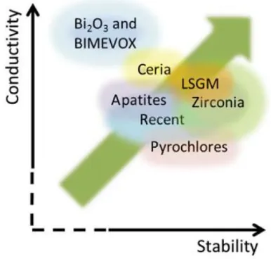
electrolyte material due to its excellent stability in both fuel and air environment. The ohmic loss due to low conductivity of YSZ electrolyte can be minimized by reducing its thickness and thus can be used in the temperature range of 700-800oC instead of 1000oC (see section 2.4).Fig.11. provide a qualitative quick reference guide for some of the families of electrolytes, co-relating their conductivity and stability in the temperature range of 600-800oC.Some of these electrolyte materials are discussed individually in context of their application for MS-SOFC.
Fig.11.Selected performance indicators for temperature in the range 600-800oC. The green arrow indicates the desirable performance
trend [22].
(a) LSGM (Strontium- and magnesium
doped-lanthanum gallate)
The chief advantage of this material is that it exhibits decent oxygen ion conductivity at temperature as low as 400oC due to its nearly pure ionic conducting behavior. However, it is not suitable for long term application because of its reactive nature. LSGM has been shown to react with Cr2O3 and Cr containing vapors [23] and therefore
not preferred for use with stainless steel supports. LSGM has been applied as an electrolyte on Ni metal supports and on Ni-Fe supports using atmospheric plasma spray (APS) [24] and pulsed laser deposition respectively(PLD [25]. However, LSGM has also been found to react with Ni in the anode or Ni-Fe metal support. Nevertheless, the reaction between the electrolyte and the metal substrate was prevented by introduction of additional thin SDC (Samarium doped ceria) layer between them. Although Cells with these designs showed notable power densities ranging from 100mWcm-2 to 1.6 Wcm-2 at 400oC and 600oC respectively, the power densities dropped by roughly 50% upon a thermal cycle. No long term operation has been reported. Recently, Lanthanum doped ceria (LDC) thin layer was used between LSGM electrolyte and Ni based anode to prevent the reaction of Ni with LSGM [26].
(b) CGO (Gadolinium-doped ceria)
32
Fig.12. shows that open circuit voltage (OCV) can drop below 0.8-0.9 V at 600oC and higher due to mixed conduction in electrolyte, setting this as maximum operating temperature [27] [28]. Nevertheless, the electronic conduction of CGO layer can be blocked by introducing an additional thin electrolyte layer of Sc-stabilized zirconia (ScZr) between anode and CGO as shown by Hui et al [29] [30].This Metal supported cell with additional electrolyte layer showed improved performance. Although the lower operating temperature of 500-600oC is advantageous in terms of stability and performance of the metal support, and the requirement of less expensive balance of plant material, it does not allow the internal reforming of the hydrocarbon fuels [27] [31]. Thus there is a need of pre-reformer which adds up to the cost and the complexity of the system.
An advantage of ceria based electrolytes is that it allows the use of prefabricated metal supports which shrinks very less or does not shrink at all. This is because these electrolytes can be sintered to full density under constraint geometry. Moreover, electrophoretically deposited CGO electrolyte can be sintered to full density at temperature as low as 1000oC [27].Low temperature sintering of CGO electrolyte can also be achieved by appropriate dopants [32] [33] [34]. These low sintering temperatures allows the sintering of CGO electrolyte on stainless steel substrates in air without excessive oxidation of the substrate. Furthermore, dense ceria based electrolytes can be obtained on metal substrates at even lower temperatures by techniques such as RF magnetron sputtering [35], pulsed laser deposition [29] [30], spray pyrolysis [36] and various plasma spray techniques [37] [38] [28]without the need of further heat treatment.
Fig.12.Theoretical open circuit voltage Eth and measured open circuit voltage VOCV over 450-600
o
C for a metal supported cell with Ni-SD anode, SDC electrolyte, and SSC-SDC cathode operated with
humidified hydrogen and air [28].
(c) YSZ (Y
2O
3stabilized ZrO
2)
34
or flame-spray, or co-sintering to full density after colloidal/wet deposition of YSZ on green substrate. These routes to obtain dense electrolyte on metal substrate have their own merits and demerits and are discussed ahead [11].
Plasma spray deposition of YSZ allows the deposition of nearly dense YSZ layer on the prefabricated metal substrate. Complete densification can then be achieved by thermal treatment at relatively lower temperature. This allows the metal substrate to retain high porosity during fabrication. However, electrolyte thickness of 30-70µ is necessary to ensure the gas tightness of the electrolyte layer. Also, the ionic apparent conductivity of plasma deposited YSZ is lower than sintered YSZ [41]. These factors require the cell to operate at least 800oC, which can in turn lead to excessive oxidation of substrate as discussed earlier (see section 2.5.1.b).German aerospace center (DLR) and collaborator have pioneered the plasma deposition of YSZ electrolyte for MS-SOFC [42] [43] [44] [41].Some of the recent works on plasma spray deposition of YSZ for MS-SOFC are [45] [46] [47]. A review on plasma spray deposition technique for various components of SOFC is given by [48] .
substrates. YSZ shrinks between 10-25% depending on the green density. It is necessary that the shrinkage of substrate matches with that of the electrolyte or else the electrolyte will be held in tension during co-sintering, forming cracks. It can be very challenging to obtain sufficient shrinkage for substrate while still retaining sufficient porosity. This can be however achieved by care full combination of particle size, granulometery, initial packing density, amount of pore former and amount of binders [49].MS-SOFC fabricated by co-sintering approach have been reported to show good performance [50] [51], stability [52] [51], excellent thermal cycling resistance [53] [54] and good redox cycling resistance [53]. Fig.13 shows power density above 1.2 W/cm2 at 700oC for a co-sintered MS-SOFC [50].
Fig.13. Performance of MS-SOFC with YSZ electrolyte obtained by co-sintering. Measurements were carried out with humidified hydrogen and oxygen. Ni anode catalyst and LSM cathode catalyst
36
2.5.3. Cathode Materials
Electrochemical reduction of oxygen takes place at cathode/electrolyte interface and therefore the cathode should satisfy the following requirements. It should have high electronic and ionic conductivity and should possess high electrocatalytic activity for cathode oxygen reduction. It should be chemically stable under fabricating and operating conditions. TEC of cathode should match with other cell component and it should be compatible with electrolyte and interconnect materials it is in contact with. Finally, it should have a stable, porous microstructure.
The typical cathodes decompose when sintered in inert or vacuum atmosphere which is necessary to prevent oxidation of metal substrate [55]. Cathodes are therefore restricted for sintering in air below 900oC after all high temperature, non-oxidsing processing steps. Such temperatures are not high enough as the cathode materials like LSM (Sr doped LaMnO3) and LSCF (Lanthanum
strontium cobaltite ferrite) requires to be sintered between 1000-1200oC to achieve high performance. Although SDC-Sm0.5Sr0.5CoO3
(SSC) composite cathodes show good performance when sintered at relatively low temperature of 800oC [56] [29] [36] [30] [37] [38] [28] , they are not suitable due to their high TEC (18.4ppm-1).Moreover, both LSCF and SSC are susceptible to Cr poisoning [23]. LNF (La(Ni)FeO3) cathode is recommended for MS-SOFC application as it
is tolerant to presence of Cr [57] [58] [59] and shows good performance at sintering temperature as low as 800oC [60].Lately, some other studies were also carried on cathode material which could be directly sintered in situ during operation for MSOFC. (Bi2O3)0.7(Er2O7)0.3-Ag composite cathode was sintered in situ at
and air [61]. Kim et.al did a comparative study of unsintered BSCF (Ba-Sr-Co ferrite), LSCF and LSM cathode materials [62]. The study was carried out on ASC having the unsintered cathode materials at 800oC among which BSCF showed the best performance Fig.14.The MS-SOFC with unsintered BSCF showed maximum power density of 820 mW cm-2 at 800oC with H2-3%H2O and air.
Nonetheless, the above mentioned processing limitations can be overcome by catalyst infiltration approach for cathode fabrication. In this route the molten salt of metal that comprise the catalyst is infiltrated in ‘porous support/porous YSZ/dense YSZ’ geometry after its processing at high temperature in reducing atmosphere. The salts can then be decomposed between 400-600oC to give the desired oxide catalyst composition [63].
It should be noted that deposition of cathode materials like LSM or LSCF for MS-SOFC have also been done by plasma spray [42] [41].
Fig.14. Performance of ASC with unsintered BSCF, LSM and LSCF cathodes at 800oC with H2-3%H2O and air at anode and cathode
38
2.5.4. Anode Material
The function of the anode material is to provide sites for the oxidation of fuel and to enable the charge neutralization by electronic conduction. The anode must be an excellent catalyst for the oxidation of fuel. It should be: electronically conducting, sufficiently porous, stable in oxidizing and reducing atmosphere, and have TEC closely matching with that of electrolyte and substrate. Furthermore it should be chemically stable with components it is in contact with, such as substrate and the electrolyte. Finally it should be applicable with various fuel and impurities like sulphur.
Ni/YSZ cermet has been the most preferred anode material for the previous generations of SOFCs. Same anode material has been considered for the MS-SOFC by most of the developers. Ni/YSZ cermet, however imparts some fabrication issues. Any MS-SOFC fabrication approach involving temperature above 900oC should be carried out in inert atmosphere (typically Ar-3%H2) or high vacuum to
prevent excessive substrate oxidation. Such condition leads to reduction of NiO (initially used) during fabrication itself and causes coarsening of Ni phase in the anode. For instance, Fig.15. shows the microstructure of a cell fabricated at 1400oC in H2 and cell fabricated
at high temperature in air and then reduced at 800oC in H2
[64].Coarsened Ni grains with non-homogenous microstructure can
be seen for cell sintered at 1400oC in H2. Ni coarsening decreases the
Austenisation of ferritic stainless steel is problematic because it can cause the mismatch in TEC of substrate with that of other cell components. The interdiffusion and coarsening due to high temperature fabrication processes can be avoided by using low temperature processes such as plasma spray for the deposition of anode and electrolyte. However, interdiffusion still occurs during the long term operation of the cell as shown in Fig.16. [43].
Fig.15. Electrolyte and anode microstructure of (a) Cell sintered at 1400oC in H2 and (b) Cell sintered at high temperature in air and then
reduced at 800oC in H2.Comparativelylarge (coarsened) Ni grains with non-homogenous microstructure can be seen for cell sintered at
1400oC in H2.[64].
40
Nevertheless, the issues of high temperature coarsening and interdiffusion have been addressed by infiltration approach for anode. Use of diffusion barrier layer (DBL) between anode and steel substrate has also shown to prevent interdiffusion. These topics will be addressed in detail in section 2.6.2.
2.6. Fabrication of MS-SOFC
The presence of metallic substrate in the design makes the fabrication of MS-SOFC quite challenging. Unlike the conventional ceramic or cermet supported SOFC, care should be taken that high temperature fabrication steps for MS-SOFC is carried out in inert atmosphere or vacuum to prevent substrate oxidation. Also, the sintering temperature may not be too high (necessary to obtain gas tight electrolyte) which otherwise can lead to limited porosity or the melting of the substrate. Moreover, the less or no shrinkage exhibited by the substrate during fabrication demands to employ expensive and advanced fabrication approaches. Different approaches and techniques have been employed by developers to overcome the fabrication issues and will be discussed ahead.
In general, the MS-SOFC fabrication can be distinguished into fabrication by non-cosintering and fabrication by co-sintering route. Fig.17. shows the schematic representation of techniques used for MS-SOFC fabrication by the two approaches.
2.6.1. Fabrication by non-co-sintering routes
42
dense or nearly dense state; it does not require the high temperature sintering step and shrinkage for densification. The film deposition technique for depositing functional layers include physical / vapor / plasma deposition methods. This fabrication route is often called as “low temperature route” as the layers are produced at lower temperature. Fig.19. shows the SEM image of the MS-SOFC fabricated by plasma spray deposition of active layers on the porous stainless steel 430 substrate [47]. This approach is actively developed by different groups for e.g. National Research Council
Fig.17. Schematic representation of techniques used for MS-SOFC fabrication by the two approaches. It should be noted that 1) For
co-sintering route, the sequence of deposition can be
techniques on the preformed substrate as it can be constraint sintered (see section 2.5.2.b)
Canada (NRC) using PLD [37] [30] and HVOF [68], and Aerospace Research Center and Space Agency (DLR) in Germany using APS and VPS [41] [42]. These fabrication processes allows fabrication of MS-SOFC in a single step by consecutively coating all the functional layers on the substrate. Another advantage is that these processes limits the coarsening of Ni in the anode and interdiffusion of Ni and Fe,Cr between anode and the substrate during fabrication. Ni coarsening and interdiffusion is a critical issue when single step co-sintering approach is considered for MS-SOFC fabrication.
Fig.18.SEM images of two different substrates: (a) perforated sheet and (b) porous one.
44
causes the substrate to have enhanced surface area and can lead to Cr depletion from bulk which is not favorable (see section 2.5.1.a)
Fig.19. SEM image of MS-SOFC fabricated by plasma spray deposition of LSM/8YSZ cathode, 8YSZ electrolyte and NiO/8YSZ
anode on the prefabricated porous ferritic stainless steel 430 substrate [47].
2.6.2. Fabrication by co-sintering routes
MS-SOFC fabrication by co-sintering route employs wet ceramic deposition techniques (tape-casting, screen-printing, wet powder spraying and spray/spin/dip- coating) for the deposition alloy substrate and the active functional layers (anode and electrolyte). The assembly is subjected to one or more co-sintering steps at high temperature in reducing atmosphere to densify the electrolyte and consolidate the AFL and substrate. The cathode layer is then deposited usually by screen printing and sintered in situ at lower temperature to avoid its decomposition (see section 2.5.3.). Since the electrolyte layer is deposited by the wet ceramic technique, high sintering temperatures are required for the densification of electrolyte. This route is therefore often called as “high temperature process”. The main advantage of this processing route is that it is economical, flexible and easy to upscale for mass production on industrial scale. However, there some serious issues related to this fabrication route.
46
anode and substrate [43] [65] [66]. The developers have employed approaches such as infiltration and the use of diffusion barrier layer to overcome these issues.
(a) Infiltration approach for co-sintering
Lawrence Berkeley National Laboratory (LBNL) in USA was the first one to come up with infiltration route [11] [53] [50]. In this approach, first the porous YSZ anode (without the catalyst) is co-sintered with metal support, electrolyte and possibly other layers at high temperature in reducing atmosphere. Catalyst (Ni) is then infiltrated by precursor method at lower temperature. The catalyst is therefore never exposed to high temperature in reducing atmosphere thus preventing coarsening and interdiffusion upon fabrication. In this approach, the anode catalyst coats the metal support as well and so, inclusion of rare earth in the precursor can improve the oxidation resistance of the support. The catalyst forms a thin layer on the porous YSZ and porous metal support backbone, and does not play any role in the mechanical integrity. Thus, catalyst with significant TEC mismatch or volume change upon redox cycling can be employed. Similarly, infiltration route can be, and is also employed for the cathode material to overcome its limitations during high temperature co-sintering (see section 2.5.3.). The infiltration route is also investigated by Riso National Laboratory in Denmark with Karlsruhe Institut fur Technologie (KIT) in Germany [51] [70]. A setback of this approach is the need for multiple-annealing cycles to achieve sufficient connectivity between catalyst particles, thereby making the process tedious. Fig.20. shows the microstructure of the cell fabricated at LBNL by co-sintering before the catalyst infiltration
Fig.20. (a) Microstructure of the cell fabricated at LBNL by cosintering before the catalyst infiltration [11], and the microstructure of anode
after Ni infiltration (b)once and (c)5 times [50].
(b) Diffusion Barrier Layer (DBL)
One way to prevent Ni and Fe,Cr interdiffusion is by insertion of DBL between substrate and the anode (Fig.21.) [3]. DBL should prevent interdiffusion of elements while allowing the electron and gas transport. It should have a TEC matching with that of other components, and should be stable and compatible with operating and processing conditions. The challenges are to make the layer porous enough to ensure gas transport and at the same time to cover all points between electrode particles and the substrate particles to inhibit interdiffusion.
Some of the efficient DBLs are the compositions including: La0.6Sr0.2Ca0.2CrO3 and La1-xSrxMnO3 [43] [44] [41]; CeO2 and
Ce0.8Gd0.2CrO3 [69]; and undisclosed compositions [65]. Fig.22.
shows a MS-SOFC with CeO2 DBL between CroFer22APU substrate
48
to be an efficient DBL [69]. It should be noted that compositions similar to LSM are expected to be unstable in fuel atmosphere [55]. Although Cr2O3 also was used as DBL, it was not very effective due
to reduction of Cr2O3 layer during cell fabrication at high temperature
in reducing atmosphere [69].
DBL addresses to the issue of elemental interdiffusion, however, it does not prevent Cr evaporation from the bulk of the substrate, and due to its porous structure cannot solve the problem of electrode poisoning by Cr.
Fig.21. Schematic representation of a porous diffusion barrier layer coated in the surface of the alloy [3].
Fig.22. MS-SOFC with CeO2 DBL between CroFer22APU substrate and Ni/YSZ anode after 165 h of operation at 800oC at (a) low
magnification and (b) high magnification [69].
2.7. Powder consolidation by tape
casting for SOFCs
50
Fig.23. Schematic overview of a typical tape casting system equipped with a Doctor Blade.
due to high impact force during milling, and also because it is more effective when it covers the well dispersed particles rather than the agglomerates. Other additives such as antifoaming agent, rheology modifiers and surfactants may be added to the slips in order to get the desired properties.
The thickness of the dry tape results from the combination of different parameters. In general, the tape thickness increases with increase in blade gap, slurry level in the reservoir and solid loading in suspension, while increasing the casting speed and the viscosity of the slurry decreases the tape thickness. Usually the thickness of the dry tape often lies in the range of one third to two third of the blade gap.
Typical defects which can affect the quality of the dried tape are large voids caused by air bubble entrapment or rapid evaporation, and presence of agglomerates or impurities. The drying stresses in the tapes can induce cracks nucleating from the defects, and are detrimental for the mechanical resistance of the final sintered product. In addition, there can be a problem of segregation of the particles with different sizes and densities, and segregation of binders at the top in the case of thick tapes. This can lead to differential density in the green tape which in turn leads to bending and cracking during sintering. Although these problems cannot be completely avoided, it can be reduced to great extent. The reader in suggested to refer [72] [73] for deeper knowledge.
52
binder burnout and pre-sintering step can be avoided. Additionally, the time for the half cell production can be reduced significantly.
54
2.8. De-binding and sintering
Once the green sample is produced, the next step is the heat treatment in order to consolidate and to obtain desired microstructure. During firing the green sample shrinks, reducing the porosity and increasing the mechanical properties. The first step is usually the loss of organic binders which is then followed by sintering during heat treatment. The binder loss is carried out by slowly heating a green sample, and it takes place usually between 400-700oC.During sintering, the joining of the particle and the reduction of porosity of the body occurs by atomic diffusion in the solid state. In the following section just a brief overview of sintering process is given, however there are numbers of books which covers the complex aspects of powder sintering [74] [75] [76] [77].
2.8.1. Driving force for sintering
For the sintering to take place the free energy of the system must be reduced. The sources which lower the free energy of the system provide the driving force for sintering. The possible driving forces for sintering are:
1. Curvature of the particle surface 2. Externally applied pressure 3. Chemical reaction
In the absence of chemical reactions and externally applied pressure, the decrease in surface free energy Es of a system is given by [75]:
Where a is the radius, is the molar volume and is the specific
surface energy of the particles comprising the system.
The decrease in surface energy is therefore inversely proportional to particle radius.
2.8.2. Matter transport
Driving force stimulates the sintering, but the actual sintering process requires matter transport to take place. In crystalline solids the matter transport takes place via diffusion process involving atoms, ions or molecules [75]. The presence of defects in the crystal lattice allows the mass transport to take place. The defects can be classified in 3 types; 1) point defects such as vacancies, interstitial atoms, and substitutional atoms, 2) line defects (dislocations) and 3) planar defects such as free surfaces, grain boundaries, stacking faults, and crystallographic shear planes. Point defects govern the rate of matter transport through the lattice, and the concentration of such defects can be controlled by variables such as temperature, oxygen partial pressure (for oxides) and dopant concentration.
2.8.3. Mechanism of sintering
56
always be the sink for matter transport. Hence the mechanism is defined depending on the source of the matter and the path it follows to the sink. Table 3. describes the six different sintering mechanisms out of which only few contributes for densification as indicated in the table [77].
Fig.25. Path of matter transport during sintering [77].
Mechanism Source of Matter
Sink of matter
Densifying 1. Surface diffusion Surface Neck No 2. Lattice diffusion Surface Neck No 3. Vapor transport Surface Neck No 4.Grain boundary diffusion Grain boundary Neck Yes 5. Lattice diffusion Grain boundary Neck Yes 6 Plastic flow Dislocations Neck Yes
2.9. Constrained sintering
58
Fig.26. Schematic illustrations of structures which undergo differential densification: (a) composite material where porous matrix densifies around rigid inclusion or agglomerate, (b) thin film densifying on rigid substrate, (c) sintering of multilayers with different densification rates
and (d) structure with density gradient [78].
2.9.1. Constrained sintering of thin film on a
rigid substrate
Fig.27. Geometry of a thin film attached on a rigid substrate. No shrinkage occurs in the plane of the film (xy palne); all the shrinkage
occurs in the direction perpendicular to the plane of the film (the z direction).
The volumetric densification rate of the constrained film on a rigid substrate can be given as [77]
( ) [ ( )]
where ρ is the relative density of the film, and the dot denotes t
![Table 1. Overview of different types of fuel cells [2] [5].](https://thumb-us.123doks.com/thumbv2/123dok_us/541948.2053606/16.420.71.355.108.381/table-overview-different-types-fuel-cells.webp)
![Table 2. Comparison of key properties of selected alloys [3] . a average between 25 and 900oC -6-1](https://thumb-us.123doks.com/thumbv2/123dok_us/541948.2053606/33.420.71.349.75.316/table-comparison-key-properties-selected-alloys-average-oc.webp)
![Fig.25. Path of matter transport during sintering [77].](https://thumb-us.123doks.com/thumbv2/123dok_us/541948.2053606/65.420.112.304.140.344/fig-path-matter-transport-sintering.webp)
