e-ISSN: 2278-067X, p-ISSN: 2278-800X, www.ijerd.com
Volume 12, Issue 10 (October 2016), PP.15-20
Design and Implementation of a Microcontroller-Based Water
Level Control System with Seven Segment Display for Domestic
and Laboratory Application
Kufre Esenowo Jack
1, Emmanuel O. Nwangwu
2, Israel Agwu Etu
3And
Ernest Ugwunna Osuagwu
4Department Of Electrical/Electronic Engineering Technology,Akanuibiam Federal Polytechnic Unwana, Afikpo, Ebonyi State, Nigeria
Abstract:
The domestic and laboratory applicability of a microcontroller-based water level control system isthe focus of this paper. The inability to determine the upper and lower water levels in an overhead tank as well as its inability to initiate an action, warrants a control action to stop or start the pump when the water level is low or high, this is what informed the decision of this research. The use of Electronic, Electrical Machines and other associated component in designing this system, forms the basis of the methods adopted to accomplish this task. In this design when the fluid level reaches 100 percent the system stops pumping and at 20 percent, the level sensor senses that the tank is empty and the microcontroller automatically initiates the pumping following the instructions contained in the source code. In-between these two set points; any level the water reaches, the seven-segment IC will display the output. When the water table for any particular area is so low that the pump cannot suck the water, an underground sensor detects it and after three minutes, operates an alarm for the user. The design was simulated using software (proteus 8) and implemented using hardware components. The cycle continues and aids domestic residents in pumping water without switching any pump manually. This design also can also serve as a demonstration module for laboratory experimentation.
Keywords:
Water Level, Control System, Laboratory Application, Seven Segment Display, Implementation andDesign
IV. Introduction
Most often, to design a system will not pose any problem but the development is always a difficult task. To develop here means to implement the design. Before now generating set will be put ON and the pumping machine switchedfor the water to fill the tank in our domestic settings without precaution for possible wastage. Sometimes the public power supply switch gear will be left ON and the occupants of the premises will leave for work, thus when the public power supply comes the pump will be forced to over work itself, as well as wasting the water. This waste can damage the environment if nobody is available to apply control (Reza et al, 2010).
In the laboratory and industries, this module can be applied to demonstrate the control characteristic of the microcontroller(Jagadal and Halse, 2013).It can find good application in laboratory experiments as well as the oil and gas industry. The difference will only be in the type of sensor used to sense the level of the fluid being managed. The laboratory application of this module is perfect in the demonstration of flow and level measurements (Jack and Etu, 2015). In this type of exercise, proportionality is maintained in the rate of inflow of fluid with respect to the rate of outflow of the fluid from the container (Uddin, et al, 2013).
The concept of this design can also find its application in the public water supply corporations where the flow of water needs to be controlled to avoid disaster. On the whole, the idea behind this design is to realize a system that can automatically pump water from a borehole up to an overhead tank, showing a display of the water level and at the same time controlling the level so that the tank does not go dry or get overfilled.
V. Task Statement
The purpose of this research is to design and implement a microcontroller-based water level control system with seven segment display for domestic and laboratory application. To achieve this purpose, the following bjectives will be considered:
1. To design a microcontroller-based water control system for laboratory demonstration;
2. To design and incorporate an interactive medium between the user and the pumping system (display); 3. To design a suitable system that is capable of reducing human labour from the convectional manual
operation of pump;
5. To design an intelligent system that is capable of sensing when the underground water level cannot be reached;
6. To design a system that can automatically control water level thus saving energy, since the demand for electricity is very high.
VI.
Related Work: Conceptual Principles
Several researchers have worked on water or liquid level control systems with different results and modus operandi. In one of the research works, Ebere and Francisca (2013) designed a microcontroller based water level control system for the purpose of starting and stopping a pump, as well as display the level of the water in the tank. The system has the same objective as this design but differs in the type of sensor and display units.While they used comparators as sensors and LCD as display units, this design used metallic sensors and seven-segment ICs as display units. Furthermore, this design used PIC microcontroller embedded with C language while the other design used ATMEGA microcontrolller embedded with assembly language.
In a related development, Jatmikoet al, (2012) developed a prototype module for detecting the level of water, with wireless system. The module used an ultra sound sensor (ping sensor) to transmit and receive signal between the position of the sensor and the water (Abdullah et al, 2014; Viswanathet al, 2015). The microcontroller used was ATMEGA and the output device was LED and LCD. The technicality behind this module is different from that of this design in the type of sensor and the output device. However, they produce the same result of detecting water level. It is generally obvious that microcontroller has got a significant role to play in level control(Patil and Abrar, 2014). It is on this note that Chakraborty et al (2014) also worked on a water level control system using PIC microcontroller. This design is similar to this work in that it was meant for a residential building. The design used USART interface to communicate the water level status to a computer.
The wireless and ATMEGA microcontroller gained popularity in level control system as the metal strip sensor which operates in the principles of electrical conductor of water was used for level control using radio frequency via Global System for Mobile (GSM) communication. The GSM was used in transmitting and receiving signal with an interface to the computer system for displaying only HIGH or LOW level for the control action to be taken (Mukthaet al, 2013; Nnadiet al, 2015; Makanjuolaet al, 2015). This design is similar to this research design work in that it was meant for a residential building but will incorporate an intelligent device that will give alarm when the water level underground cannot be reached. Under this condition, the system is shut down after three seconds.
Very recently, Teo and Tiew (2015) embarked on a similar venture where the Water Level Automated Management System was introduced. The information to top-up water from a reservoir tank when the water level in the main tank falls below half of the tank; was sent through SMS to the user. When it falls below the critical level, the buzzer will be activated to warn the user of the critical state of the system. Peak microcontroller PIC16F84A was adopted for this design. The water level sensor here was water conductivity sensor. The ON/OFF sensors were used to sense the presence of water at a particular level (Umeh et al, 2015). Obikoya (2014) deviated a little from the water control system into fuel. The researcher designed, constructed, and implemented a remote fuel-level monitoring system. The system was uniquely configured such that the remote Aplicom 12 GSM module interfaced the connected sensor. Here the status message from the module was sent back via a Global System for Mobile (GSM) Communications network (Johari et al, 2011; Abdullah1 and Ali, 2014). The fuel-level sensor was designed and uses arms and floater, where the displacement of the fluid from the floater was converted to a readable value. Their work has flaws in that in cases of network failure, there won’t be any other medium of communication thereby bringing the entire system to a halt.
Based on this conceptual principle, this Microcontroller-Based Water Level Control System was designed. The materials listed below were technically selected for this design and the experimental approaches form the method suitable for this design piece.
VI. Materials and Method
Materialsi.
Water Level Indicator: Seven Segment Display ICii.
Microcontroller:PIC16F877Aiii.
Water Level Sensor: Metal plate Sensoriv.
Water Pumpv.
Others
a. Resistorsd. Darlington transistor IC :ULN2823 e. Water reservoir tank
f. Buzzer alarm g. Transistors h. Relay
VII.
Methodology
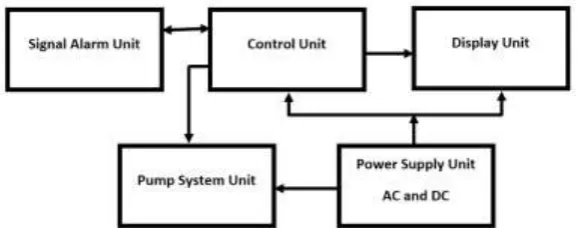
The above listed components and materials were practically put together to realize this design. This experimental block is an illustration of how the components were combined at each stage:
Figure 1: Block diagram of Microcontroller-Based Water Level Control System
Figure 2: Circuit diagram of Microcontroller-Based Water Level Control System
Design Procedure
This water level control system was designed bearing certain conditions in mind. Some of the conditions include using seven-segment IC for output display, using buzzer to give signal for the absence of underground water, using microcontroller to issue control, using Darlington transistor IC as a buffer, and so on. The first consideration was to think of the type of microcontroller to use vis-a-vis the programing language. The microcontroller of choice here was PIC16F877A and the programing language was C language. PORT C of the microcontroller was used as input while PORTs A, B, D and E was configured to serve as outputs. The microcontroller initialization of PORT direction in C language are as shown below:
#include <pic.h>
#define XTAL_FREQ 4000000 Void main (){
PORT A was devoted to seven-segment display 1 which displays the hundredth value. The microcontroller is meant to send logic 1 or logic 0 to the bases of the responsible transistors to trigger them into the necessary conduction state that will light the segment of the display to show a figure. The seven-segment IC used here is the common anode type.
PORT B was used to drive seven-segment 2 which displays the tenth value. The same principle applied to PORT A and seven-segment 1 also applies here. Moreover, one of the pins in PORT B (pin RB7) is used to drive a buzzer which signals the user of lack of underground water in the soil.
PORT D was used to drive seven-segment 3 which displays the unit value. The same principle applied to PORTs A and B and their seven-segment ICs also applies here. Moreover, one of the pins in PORT D (pin RD7) is used to drive a transistor which triggers the pump ON or OFF as the case may be.
PORT C receives input signal from the Darlington transistor IC. This signal is from the tank and it is logic 0 which is inverted to logic 1 and sent to the microcontroller. This logic 0 is derived as a result of the grounding of the water tank. This grounding makes any of the sensors that water touches, to assume logic zero. Moreover, pin RC6 serves as the input pin for sensing low water level in the soil.
V Implementation and Operation
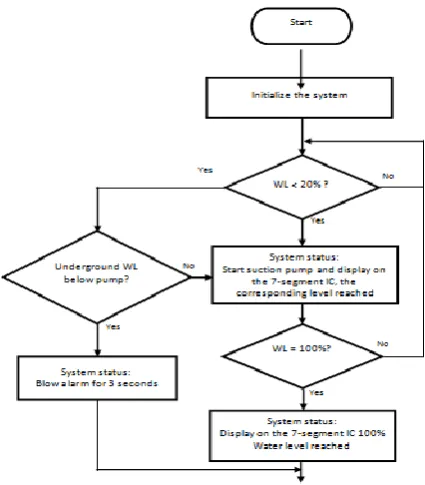
System Flow Chart
Figure 3: Microcontroller-Based Water Level Control System Flow Chat
Software Implementation
The software implementation is as shown below: #include <pic.h>
#define _XTAL_FREQ 4000000 Void main(){
PORTA=0b00000000; PORTB=0b00000000; PORTD=0b00000000; PORTE=0b000; TRISA=0b00000000; TRISB=0b00000000; TRISC=0b00000000; TRISD=0b00000000; TRISE=0b000; do{
if(RC4=1){RA0=0; RA1=1; RA2=1; RA3=1; RA4=1; RA5=1; RE0=1; RB0=1; RB1=1; RB2=0; RB3=1; RB4=1; RB5=0; RB6=1; RD0=1; RD1=1; RD2=1; RD3=1; RD4=1; RD5=1; RD6=0;}
if(RC3=1){RA0=0; RA1=1; RA2=1; RA3=1; RA4=1; RA5=1; RE0=1; RB0=1; RB1=1; RB2=0; RB3=1; RB4=1; RB5=0; RB6=1; RD0=1; RD1=0; RD2=1; RD3=1; RD4=0; RD5=1; RD6=1;}
if(RC2=1){RA0=0; RA1=1; RA2=1; RA3=1; RA4=1; RA5=1; RE0=1; RB0=1; RB1=0; RB2=1; RB3=1; RB4=0; RB5=1; RB6=1; RD0=1; RD1=1; RD2=1; RD3=1; RD4=1; RD5=1; RD6=0;}
if(RC1=1){RA0=0; RA1=1; RA2=1; RA3=1; RA4=1; RA5=1; RE0=1; RB0=1; RB1=1; RB2=1; RB3=0; RB4=0; RB5=0; RB6=0; RD0=1; RD1=0; RD2=1; RD3=1; RD4=0; RD5=1; RD6=1;}
if(RC0=1){RD7=0;RA0=0; RA1=1; RA2=1; RA3=0; RA4=0; RA5=0; RE0=0; RB0=1; RB1=1; RB2=1; RB3=1; RB4=1; RB5=1; RB6=0; RD0=1; RD1=1; RD2=1; RD3=1; RD4=1; RD5=1; RD6=0;}
if(RC6=0){__delay_ms(3000); RB7=1; RD7=0;} }while(1);
}
Hardware Implementation
The hardware implementation of this design centres on the microcontroller. There are six sensors inside the water tank.
The tank itself is connected to the ground line. The source code was written in such a way that when the water level is at the lowest sensor (sensor 0), the sensor assumes logic 0 (that is, ground from the tank). The ULN2823 Darlington transistor IC inverts the logic 0 to logic 1 and feeds the microcontroller with it. Apart from converting logic signals, this IC also acts as a buffer, to add strength to signals when the distance between the tank and the position of the display unit is very long. The code instructs the microcontroller to output digit zero on seven-segment 1, 2 and 3 thereby displaying zero level. When water level reaches sensor 1, the code instructs the microcontroller to output 0, 2 and 0 thereby displaying level 20%. This continues for level 50%, 75% and 100%. At 100% water level, the microcontroller triggers OFF the pump to avoid waste of power and water. Furthermore, there is a sensor that detects the presence and absence of underground water. As long as water touches this sensor, the system will continue to work normally. However, once the underground water level falls below this sensor, it will wait for three seconds and then trigger ON the buzzer and at the same time switch OFF the pump if it was operating. This is to prevent the pump from breaking down due to overworking.
The flow chart above also helps to explain this logical operation in a very simple form. While a novice may wish to understand the operational principle with that, engineering professionals may wish to go through the code.
VI. Results and Discussion
The hardware and software implementations have given a clue of what the result will look like. Basically, once the system is ON the microcontroller begins to scan to see which of the conditions in the code that is fulfilled. The fulfillment of any of the conditions is as a result of the condition the sensors find themselves. Whichever condition that is fulfilled, the microcontroller performs the corresponding operation. When the tank is empty, the output will be a display of 000 on the three seven-segment ICs. As the pump begins to pump water, the displays will be showing the system status as the level of water in the tank in the following order: 020, 025, 050, 075 and 100. At 100% the system switches OFF the pump. Again, if the underground water level falls lower than the pump, the system blows alarm and switches OFF the pump. Some other features are captured in the summary and conclusion.
VIII.
Summary and Conclusion
switching any pump manually. The design was actually a demonstrative module for laboratory experimentation as well as a relief for the domestic problem which were long overdue for solution.
References
[1]. Abang, J. O. (2013). Construction of Automatic Water Level Controller for Both Overhead and Underground Tanks. Journal of Chemical Information and Modeling, 53(1), 1689–1699.
[2]. Abdullah,U. & Ali, A. (2014). GSM Based Water level and Temperature Monitoring System. International Journal of Recent Development in Engineering and Technology, 3(2), 1–7.
[3]. Abdullah,A.M.; Ahmed, N.;Ahmed, N. U.;Matiur-Rahman, S.A.M; Ahmed, B. & Sundara, K. (2014). Use of Wireless Sensor and Microcontroller to Develop Water-level Monitoring System Use of Wireless Sensor and Microcontroller to Develop Water-level Monitoring System. Indian Journal of Science and Technology, 7(9), 1325–1330.
[4]. Chakraborty, T.; Alam, K.; Mal, S. & Biswas, U. (2014). Automatic Electronic Water Level Management System using PIC Microcontroller. International Journal of Emerging Technology and Advanced Engineering, 4(7), 30–33.
[5]. Ebere, E. V. & Francisca, O. O. (2013). Microcontroller based Automatic Water level Control System. International Journal of Innovative Research in Computer and Communication Engineering, 1(6), 1390–1396.
[6]. Fisher, D. K. & Sui, R. (2013). An inexpensive open-source ultrasonic sensing system for monitoring liquid levels. Agricultural Engineering International: CIGR Journal, 15(4), 328–334.
[7]. Jack, K. E. and Etu, I. (2015). Applied Electrical Electronics Measurement Principles & Instrumentation Systems with Laboraor y Experiments. Kingdom Age Publications, Enugu, Nigeria
[8]. Jagadal, S. B. & Halse, S. V. (2013). 8051 Microcontroller Based Multiple Water Tank Control System. Journal of Computer & Mathematical Sciences, 4(5), 382–401.
[9]. Jatmiko, S.; Mutiara, A B. & Indriati, M. (2012). Prototype of Water Level Detection System. Theoretical and Applied Information Technology, 37(1), 52–59.
[10]. Johari, A.; Helmy, M.; Wahab, A.; Suryani, N.; Latif, A.; Ayob, M. E.& Ayob, M. A. (2011). Tank Water Level Monitoring System using GSM Network. International Journal of Computer Science and Information Technologies, 2(3), 1114–1120.
[11]. Makanjuola, N.T; Shoewu, O.O; Akinyemi, D. & Ajasa, A. (2015). Design and Development of Microcontroller Based Liquid Level Detector with. The Pacific Journal of Science and Technology, 16(1), 173–181.
[12]. Muktha, S. K; Jyothi, K.; Manu, E. O.; Naveen, I. P. & Herle, H. (2013). Wireless Automatic Water Level Control using Radio Frequency Communication . International Journal of Advanced Rresearch in Electrical, Electronics and Instrumentation Engineering, 2(4), 1320–1324.
[13]. Nnadi, D.B.N;Oti, S.E & Ezika, P. C. (2015). Radio Frequency Based Water Level Monitor and Controller for Residential Applications. Nigerian Journal of Technology, 34(3), 573–581.
[14]. Obikoya, G. (2014). Design, construction, and implementation of a remote fuel-level monitoring system. EURASIP Journal on Wireless Communications and Networking, 2014(1), 76.
[15]. Parade, D.& Group, B. & Dublin, C. (2015). Low-Power Wireless Liquid Monitoring System Using Ultrasonic Sensors. International Journal on Smart Sensing and Intelligent System, 8(1), 26–44.
[16]. Patil,R. R.& Abrar, M. M. (2014). Logic gate based automatic water level controller. International Journal of Research in Engineering and Technology, 3(4), 477–482.
[17]. Reza, S. M. K.; Tariq,S. M.; Reza, S. M. M.; Douglas, C.; Grundfest, W. S. & Burgstone, J. (2010). Microcontroller Based Automated Water Level Sensing and Controlling: Design and Implementation Issue. World Congress on Engineering and Computer Science, Vols 1 and 2, I(2010), 220–224.
[18]. Teo, P. & Tiew, C. D. (2015). Automated Water Level Management System. International Journal of Computer & Electronics Research, 4(1), 11–16.
[19]. Uddin, M.S.M; Alam, R.M; Bansal, M; Akhter, P; Baidya, R & Kabeer, R. (2013). Design and Implementation of Microcontroller Based Process Line. International Conference on Mechanical Engineering and Renewable Energy, 2013(December), 24–27. [20]. Umeh,M.N; Mbeledogu, N. N; Okafor, S. O. & Agba, F. C. (2015). Intelligent microcontroller-based irrigation system with sensors.