120 | P a g e
THREE PHASE POWER FLOW MANAGEMENT
USING INTERLINE POWER FLOW CONTROLLER
IPFC UNDER THREE PHASE FAULTS
1
TIRUVEEDULA AVINASH
,
K.SURESH
21
pursuing M.Tech (EEE),
2
working as Assistant Professor (EEE),
Nalanda Institute Of Engineering and Technology (NIET), Kantepudi(V), Sattenpalli(M), Guntur (D),
Andhra Pradesh (India)
ABSTRACT
The interline power flow controller (IPFC) is a modern generation flexible AC transmission systems (FACTS)
controller utilized to enhanced power flows of multiple transmission lines. The main theme of this paper is
comprehensive study about a new real and reactive power synchronization compensator for a interline power
flow controller (IPFC). The essential control for the IPFC is such that the series controller of the transmission
line real/reactive power flow and also compensate the bus voltage by reactive power and the DC link
capacitor voltage. Because the Dc link Capacitance is able to convey real power to any other and in that way
make possible real power transfer among the lines of the transmission system. Because the converter is able to
offer reactive compensation, the (IPFC) is capable to take out an overall real and reactive power
compensation of the whole transmission system. This potential makes it possible to match both real and
reactive power flow among the lines, transfer power from three phase faults, compensate beside reactive
voltage drops and equivalent reactive line power and to enlarge the efficiency of the compensating system
against dynamic conflicts. A simulation model in MATLAB has been completed in order to extend predictable
algorithm based on the required model.
Keywords:
Power System Modeling, FACTS Controllers, UPFC, IPFC, Power Flow, Small
Signal Stability, Voltage Source Converter, Mat Lab Software
I. INTRODUCTION
Power framework solidness has been perceived as an imperative issue for its protected operation since 1920s
[1][2]. After effect of the first research facility tests on smaller than usual frameworks were accounted for in
1924 [3]; The first field tests on the dependability on a pragmatic force framework were directed in 1925.
Traditionally, the issue of steadiness has been one of keeping up the synchronous operation of generators
working in parallel, known as rotor point strength. The issue of rotor point strength is surely known and
121 | P a g e
With consistent increment in force request, and because of restricted extension of transmission frameworks,
advanced force framework systems are being worked under exceptionally focused on conditions. This has
been forced the danger of keeping up the required transport voltage, and accordingly the frameworks have
been confronting voltage precariousness issue [4][5].
Because of expansion in force request, cutting edge power framework systems are being worked under much
focused on conditions. This has come about into the trouble in meeting receptive force necessity, particularly
under possibilities, and henceforth keeping up the transport voltage inside adequate points of confinement.
Voltage flimsiness in the framework, by and large, happens as a dynamic rot in stumbling of a transmission
line, burden shedding and under burden tap changer activity.
1.1 Scope of Present Exploration
Goal of Interline Power Flow Controller (IPFC) is to give a complete force stream control plan for a multi-line
transmission framework, in which two or more lines utilize a SSSC for arrangement pay.
A multiline IPFC contains number of "n" SSSC's, one for every line of the transmission framework to be
controlled, with a typical dc transport as delineated schematically by a piece graph as appeared in Fig: 1.
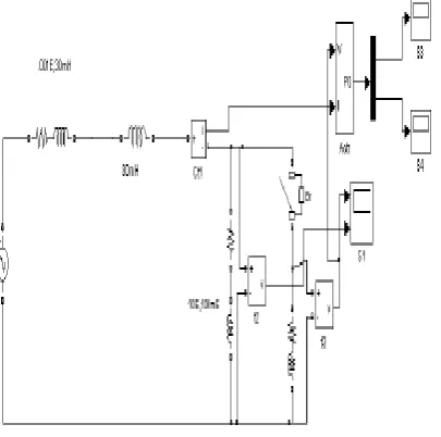
Consider an IPFC plan appeared in Fig: 2 comprising of two consecutive dc to air conditioning inverter each
remunerating a transmission line by arrangement voltage infusion.
Fig.1. General Schematic of IPFC Transmission Line
122 | P a g e
II. OERATING PRINCIPLES
IPFC in Series Compensation Mode
A. Real Power Coordination Controller
The connection between the arrangement infused voltage (VSE) and the transmission line current (ISE)
prompts trade of genuine force between the arrangement converter and the transmission line.
The genuine force (PSE) interest of the arrangement converter (PSE) causes the dc join capacitor voltage
(VDC) to either expand or lessening relying upon the bearing of the genuine force stream from the
arrangement converter.
This abatement/increment in dc join capacitor voltage (VDC) is detected by the shunt converter controller that
controls the dc join capacitor voltage (VDC) and acts to expand/diminish the shunt converter genuine force
stream to bring the dc join capacitor voltage (VDC) back to its planned quality. On the other hand, the genuine
force interest of the arrangement converter is perceived by the shunt converter controller just by the
diminishing/increment of the dc join capacitor voltage (VDC).
B. Reactive Power Coordination Controller
The in-stage segment (VSED) of the arrangement infused voltage which has the same stage as that of the IPFC
transport voltage has extensive impact on the transmission line responsive force (QLINE) and the shunt
converter receptive force (QSH).
Any build/diminish in the transmission line responsive force (QLINE) because of in-stage part (VSED) of the
arrangement infused voltage causes an equivalent expand/diminish in the shunt converter receptive force
(QSH).
To put it plainly, the shunt converter supplies build/diminish in transmission line responsive power.
Increase/diminish in the transmission line receptive power likewise has impressive impact on the IPFC
transport voltage.
C. Power Factor Corrector
In transmission line, the force variable is controlled by method for infusing a voltage crosswise over it. The
transmission line comprises of lumped R and L parameters. Without an infusing of voltage, the force variable
is slacking in RL circuit.
By infusing extra voltage crosswise over it, the edge in the middle of V and I is diminished and the force
element is moved forward. By properly selecting the benefit of infusing voltage, the force component can be
made to solidarity.
Line Model without Compensation Circuit
An UPFC can be spoken to in the relentless state by two voltage sources speaking to principal parts of yield
voltage waveforms of the two converters and impedances being spillage reactance of the two coupling
123 | P a g e
The beneath Fig: 3 portray a two voltage source model of remuneration.
Fig 3: single transmission system without compensation model
III. PROPOSED SIMULINK MODEL
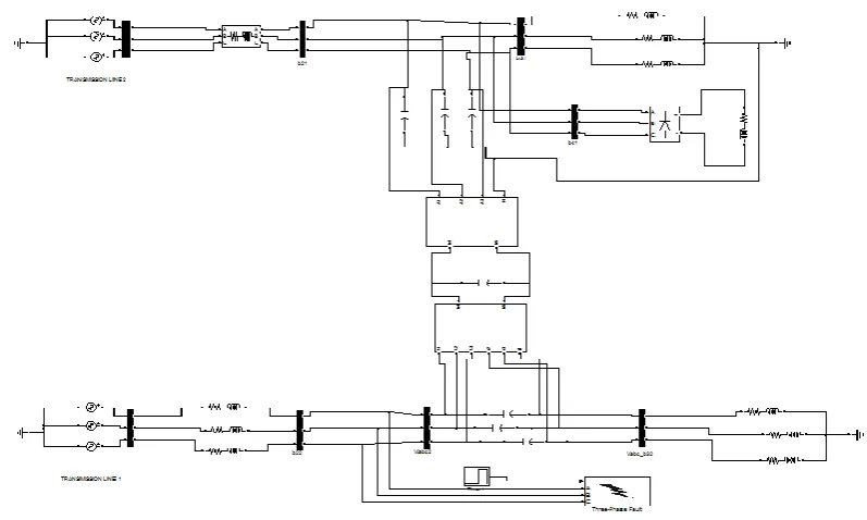
The proposed Simulink model is shown in fig 4.it consists of multiple transmission system provided by two
line three phase IPFC integration is presented.
Three individual single ac voltage sources are connected in star configuration and maintained three phase ac
voltage sources for two transmission lines. The sending side voltage is transferred to the load side.
At load side the receiving end voltage levels are always less than the sending end voltage due to different
reasons such as impedances losses, sags, swells and three phase faults, so the power flow management is
inaccurate.
In order improve the power flow transmission system for three phase under three phase problems are
presented in Simulink models.
The second line source voltage is transferred to load side by line impedances. In this analysis we are provided
the three phase problem in between the transmission lines due to this reason entire system power disturbed
which leads reduced active and reactive power levels at load side. Such conditions load requirements are not
satisfied to control these problems IPFC proposed.
The IPFC model represented series-series connected controllers to the two transmissions lines. First series
124 | P a g e
Fig 4: Proposed Three Phase Two Line IPFC Model Under Three Phase Fault Conditions
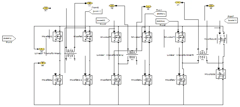
The three transformers which are connected in series to the transmission lines. The voltage source converters
containing four MOSFETS in each phase. By controlling three voltages source converts only we can control
the IPFC in order to control these series controller PWM techniques are provided.
Second series controller also designed with same as controller one such as three linear transformers connected
in series to the system and voltage source converters are contained four MOSFETS for to control voltage
function in the model it is also controlled by PWM controller. It shown in figure 6.
125 | P a g e
Fig 6: Series Controller for Second Transmission Line In Ipfc
These two series controllers are connected by common dc-link capacitance. Here non linear load also provided
at first transmission line. in the line three phase fault provided with the help of timer.
Due to non linear loads and three phase faults the entire system disturbed irregular power flow management
created. To satisfy our general applications purpose IPFC performed.
The IPFC controlled with PWM technique. For first series controller model operated with voltage source
measurements. The comparator provided for to compare required reference voltage to measured voltage at
phase 1 and it produced error signal from comparators.
The PI controllers are provided to compensate the error signals by proportional and integral gains by
improving steady state response and dynamic responses. PWM generators are provided to generate the
required firing pulses from the error less signal. These pulses are connected to first series controller.
The second controller operated with measured voltage at load side and reference voltage compared by
compactors and releases some errors from these blocks. The generated error signal is compensated by PI
controllers which increases stability of the system. The error less signal is compared by triangular signal by
relational operator, whenever the reference signal amplitude is greater than the carrier signal in those
conditions only it will generate firing pulses. These firing pulses are connected to the second controller
MOSFETS in the VSCs.
These two series controllers are connected by common dc-link capacitance. Here non linear load also provided
at first transmission line. in the line three phase fault provided with the help of timer. Due to non linear loads
and three phase faults the entire system disturbed irregular power flow management created. To satisfy our
general applications purpose IPFC performed.
The IPFC controlled with PWM technique. For first series controller model operated with voltage source
measurements. The comparator provided for to compare required reference voltage to measured voltage at
phase 1 and it produced error signal from comparators. The PI controllers are provided to compensate the error
126 | P a g e
generators are provided to generate the required firing pulses from the error less signal. These pulses are
connected to first series controller.
The second controller operated with measured voltage at load side and reference voltage compared by
compactors and releases some errors from these blocks. The generated error signal is compensated by PI
controllers which increases stability of the system. The error less signal is compared by triangular signal by
relational operator, whenever the reference signal amplitude is greater than the carrier signal in those
conditions only it will generate firing pulses. These firing pulses are connected to the second controller
MOSFETS in the VSCs.
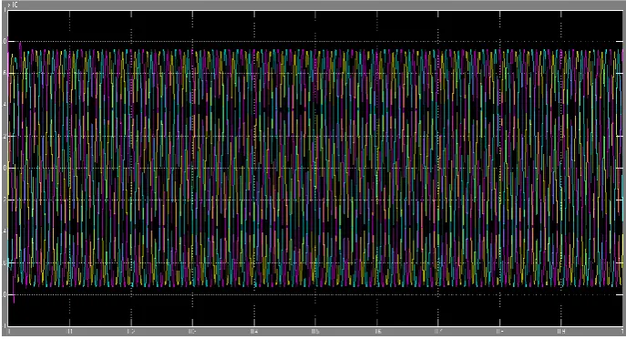
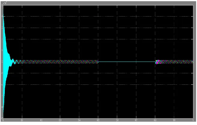
Fig 7: Output Voltage at Vabc_B22 For Second Transmission Line
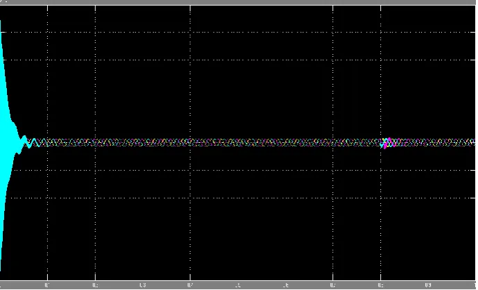
Fig 8: Output Voltage at Vabc_B31 For First Transmission Line
The generated firing pulses are integrated to the corresponding voltage source converters. In this analysis we
are provided non linear loads in the multiple transmission lines with three phase problem provided in second
transmission line with the help of timers at 0.5-0.8 at simulation time of 1.
Before compensation technique the problem was not resolved at load conditions. Whenever the compensation
127 | P a g e
two controllers are identified the problems at specified timings and operated to compensate the problems by
VSCs with capacitance. The dc link capacitance which is used store the energy levels at normal conditions and
release the energy levels at abnormal conditions.
Fig 9: Output Voltage at Vabc_B41 for First Transmission Line
The VSC converters can compensate the three phase problems effectively by PWM controllers. In this
analysis it can improves the active and reactive powers in the multiple transmission even at faulted conditions
also. By utilizing IPFC models in the transmissions lines we can maintain the required reference powers a load
side. The simulated results are shown in below figures.
128 | P a g e
Fig 11: Output Voltage at Vabc_32 for Second Transmission Line
The outputs results are shown in above figures. The fig 7 represents the voltage at Vabc_22 at second
transmission source side voltage under faulted condition by three phase fault. The fig 8 denotes the source side
voltage at first transmission system. Fig 9 explains the voltage at load side for the primary transmission
arrangement.
Fig 10 explains the output voltage in the second transmission line before compensation technique. Fig 11 gives
the information regarding the output voltage after compensation by IPFC at second transmission line.
IV.CONCLUSION
This paper presents to organize and controlling of IPFC intended for installation on a transmission line.
Simulation consequences show the efficiency of IPFC in scheming real and reactive power throughout the
line.
Also, with IPFC in transmission line, results in development of transient response of the system, which is an
supplementary benefit along with the power flow system control with a simple proper technique has been
carried out for Compensating the IEEE bus system.
It is experiential that the method has fast theoretical characteristics. In this paper I projected IPFC Series-
Series devices with double transmission lines. The successful inter line power compensator is utilized in the
specified lines for enhanced power flows, and is developed for mitigating the three phase faults under three
phase system.
The suggested analysis was depended upon series real power balance condition, when the converter losses are
abandoned. The simulations models delivers the IPFC competence and advantages for calculating concurrently
129 | P a g e
REFERENCES
1. Understanding FACTS: concepts and technology of flexible AC transmission system” N.G. Hingorani, L.
Gyugyi, ”, IEEE PRESS, 2000. Standard Publishers Distributors, Delhi.
2. D. Murali, Dr. M. Rajaram, Active and Reactive Power Flow Control using FACTS Devices International
Journal of Computer Applications (0975 – 8887) Volume 9– No.8, November 2010.
3 A. P. Usha Rani and B. S. Rama Reddy Modeling and Digital Simulation of Interline Power Flow
Controller System, International Journal of Computer and Electrical Engineering, Vol. 2, No. 3, June,
2010 1793-8163
4 Performance Evaluation of a Distance Relay as Applied to a Transmission System with UPFC. IEEE
Transactions on Power Systems. Vol.21 No.3, July 2006, Pg. No. 1137 –1147.
5. K. Manoz kumar reddy, “simulation of unified power flow controller,” proceedings of National
conference on recent trends in power systems and power electronics, (Feb 2012)148-151.
6. X. P. Zhang, “Modeling of the interline power flow controller and the generalized unified power flow
controller in Newton power flow,” Proc. Inst. Elect. Eng., Gen., Transm., Distrib., vol. 150, no. 3, pp.
268–274, May 2003.
AUTHOR DETAILS
T AVINASH Pursuing M.tech EEE IN Nalanda Institute OF engineering & Technology NIET Katepudi(v) ,Sattenapally(M) ,Gntur(D),
522438, Andra Pradesh.