3638
Design And Development Of Multi-Functional
Floor Scrubber And Cleaner.
Samarth G. Gaikwad, Shashank S. Kulkarni, Virendra P. Patil, Ashutosh S. Nagargoje
Abstract: In today’s modern era, mankind is emphasizing the use of machines in day-to-day activities which significantly reduce the time and effort required. Floor cleaning has always been most time-consuming and tedious work as it is done manually. To overcome this difficulty, automated floor cleaning machines can be utilised efficiently. The machines are not yet popular due to high price of machines, complexities in design and operating cost. Due to these reasons most of the small and medium scale industries in India are still using traditional mop and bucket system for floor cleaning. So, the main aim of this research work is to design and develop a multifunctional floor scrubber and cleaner which will substantially reduce the cleaning time and cost of the machine. At the same time, the floor cleaning machine should be capable of cleaning rough as well as smooth floors and inaccessible corners effectively. Through efficient project management, aspects like minimization of manufacturing and operational cost, aesthetic and ergonomic considerations were taken into account. Eventually this machine will lead to hefty decrease in time, money and effort.
Keywords: Floor Cleaning, Manpower Reduction, Cost of Machine, Design Complexity, Operating Cost, Manual Work, Multifunctional.
————————————————————
1. INTRODUCTION
Cleanliness plays a crucial role in adding value to ambience of any workplace such as malls, offices, industries, etc. But maintaining clean environment involves tedious work and high manpower. Also, various industries and manufacturing firms are extensively implementing 5S methodologies in their quotidian activities. The very first step in 5S implementation is maintaining a clean and tidy work environment. To accomplish this manpower required is more and it is time consuming. Hence there is a requirement of designing and developing a multi-functional floor scrubber and cleaner. Main motto of the project is to provide a much more cost-efficient machine than the ones already available in the market and at the same time will clean any type of floors efficiently. Before starting the development of machine, we studied machines available in the market. From the study we came to the conclusion that - Time, Agitation, Chemical and Temperature are four important principles which should be followed for effective cleaning. Utilising these principles will enable everyone to achieve best cleaning results.
1.1 Problem Definition
A leading manufacturer of various automotive spare parts was at inchoate stage for implementation of 5S. At this firm the cleaning of floors was done traditionally which required 8 to 10 workers who worked in two shifts of 4 hours each. This resulted in extensive fatigue of workers and also the efficiency of cleaning was not up to the mark. Various floor cleaning machines are available in market but are of high cost and have problems related to maintenance and availability of spare parts. Design and development of floor cleaning machine which will reduce the cleaning time, increase the quality of cleaning and reduce the fatigue of workers and at the same time will be cost efficient offering the same specifications as compared to readily available machines in the market.
1.2 Company Requirement
1. Design and develop semi-automatic floor cleaner which will cost up to Rs.40000.
2. The machine should clean the pathways in two passes.
3. The dirty water and clean water tanks should have a storage capacity of 50litres.
4. The machine should be aesthetically appealing and ergonomically sound.
5. The machine should be easy to maintain and the spare parts should be easily available.
6. The machine should not weigh more than 100kg when both the tanks are filled to their maximum capacity.
1.3 Objectives
1. To design and develop a cost-efficient floor cleaning machine which is 1/5th the cost of Machines available in the market.
2. To reduce the cleaning time by 1/4th the time required at present.
___________________
1.Mr. Samarth G. Gaikwad
B.E Student, Department of Mechanical Engineering, DKTE Society's Textile & Engineering Institute Ichalkaranji, Maharashtra, India.
Email Id: [email protected]
2.Mr. Shashank S. Kulkarni
B.E Student, Department of Mechanical Engineering, DKTE Society’s Textile & Engineering Institute Ichalkaranji, Maharashtra, India.
Email Id: [email protected]
3.Mr. Virendra P. Patil
B.E Student, Department of Mechanical Engineering, Padmabhshooan Vasantraodada Patil Institute of Technology, Budhgaon, Sangli, Maharashtra, India.
Email Id: [email protected] 4.Mr. Ashutosh S. Nagargoje
B.E Student, Department of Mechanical Engineering, Padmabhshooan Vasantraodada Patil Institute of Technology, Budhgaon, Sangli, Maharashtra, India.
3639 3. To drastically reduce the no. of workers by 1/4th
4. To reduce the possibility of accidents due to slippery floors
5. To increase the efficiency of cleaning than traditional mop and bucket method.
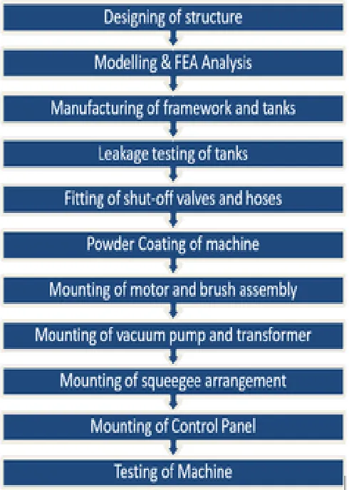
1.4 Methodology
Fig No 1: Flow chart of Work
2. DESIGN & CALCULATIONS
The main components of the machine to be designed include
1. Tanks for cleaning water and debris laden water 2. Supporting Structure of the machine
3. Vacuum and squeegee arrangement. 4. Brush and Motor Assembly.
5. Speed Reduction Pulleys.
Now considering the specifications required for ideal operation of machine various dimensions of parts are decided. The requirement for tanks being 70 litres, the dimensions are to be fixed accordingly. Final dimension of the tanks is deciding factor for designing the framework. To achieve the required rigidity various design calculations are taken into account Considering the aesthetics and ergonomics of the machine, position of the parts is approximated with the help of CAD modelling. The detailed description of design methodology is as below:
2.1 Torque requirement and selection of motor
For scrubbing the floor, the torque required to rotate the brush is the prime factor while selecting the motor. For that we considered the weight of brush, friction between brush and floor and weight of motor and pulleys. The torque required to rotate the whole assembly is calculated by using speed and torque relation. From this relation the speed at which required torque can be achieved is calculated.
1. Coefficient of friction in between sponge/ brush and floor = 0.8
2. Weight of the brush =5 kg and diameter of brush W=50 cm
3. Torque required= F x R = (0.8 x 5 x 9.81) x 0.25 T = 9.81 N-m
Formula P= Where,
P= Power N= Speed in RPM
T = Torque
550 W motor torque = 4.94 N-M at 1410 RPM. Then at 360 RPM Torque will be 9.81 N-M. Hence, here 550 W motor at 360 RPM can be used.
2.2 Design and selection of pulleys
For the required speed and torque requirements we designed the pulley arrangement. For selecting the pulleys, the diameter of the pulleys was calculated by using the standard formulae.
=
=
Hence D1= 105mm D2=26mm
2.3 Selection of vacuum pump
We have conducted the market survey and from the standard catalogues we got the data related to vacuum pump.
1mm of water = 9.81 𝑁/𝑚2
Vacuum pressure = 1733 mmH20 (From CTM Catalogue)
Therefore, Vacuum pressure = 17000.73 𝑁/𝑚2
Converting into 𝑘𝑔/𝑐𝑚2
Pressure = 0.1733 𝑘𝑔/𝑐𝑚2
2.4 Tank Dimensions:
The required capacity of tank is specified by the company which is minimum 70 litres for both the tanks.
3640 For dirty water tank,
Length = 52cm Width = 55cm Height = 25cm
Volume of tank = 52×55×25 = 71,500 cm3 V= 71.5 litres
For clean water tank,
Length = 70cm Width = 55cm Height = 20cm
Volume of tank = 70×55×20 = 77,000 cm3 V= 77 litres
2.5 Design of shaft:
1. Total load of the machine acting on the shaft = 140 kg
2. Material of the shaft: - Fe500
Now, to find out the length of the shaft,
Width of the machine= 500mm, So, width of the machine= length of the shaft
Now, finding out the reaction forces
Load acting on shaft = 140×9.81=1373.4N
Fig No 2: Load Distribution on Shaft
Now taking movement about A
RB×500- 686.7×465- 686.7×35=0 RB ×500=343350
RB=686.7N, RA=686.7N
Now to take the maximum movement for the calculation MB=0 N-mm
MC=686.7×35=24034.5N-mm.
MD = 686.7×465-686.7×430=24034.5 N-mm. MA= 0 N-mm.
Taking the Maximum Bending Moment for the calculation that is 24035.5 N-mm.
According to the formula
Now,
W= 140×9.81= 1373.4 N
D=18.22mm Where,
M = Maximum bending movement. I= polar movement of inertia. D= diameter of the shaft. W= force acting on the shaft. A= cross sectional area.
So, by solving the equation we get the value of D as 18.22mm
So, the shaft is available in size of 19.04mm that is 0.75 inch.
Therefore,
D= 19.04mm i.e. 0.75 inch
3. MODELLING & ANALYSIS
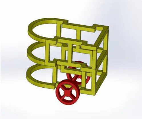
3.1 Modelling:
The modelling of the machine is done using SOLIDWORKS 2018 software. Modelling of machine helped us to get an idea how will the final machine look and make necessary changes in design and structure of machine. Firstly, we designed all the parts separately and finally assembled the parts to get the final model of our machine.
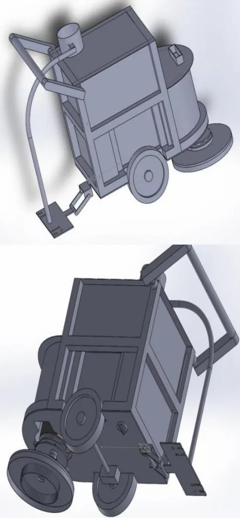
3641
Figure No 4: Final Model of Machine
3.2 FEA Analysis
A computerized method of determining the reaction of product/part to actual forces, vibrations and other physical parameters is called Finite Element Analysis (FEA). It shows whether the part will fail or sustain as per the design. For FEA analysis we used ANSYS 16.0 software. In the machine the motor mounting bracket is most vulnerable to failure. Hence it is analysed to ensure that it can withstand the forces and vibrations coming from motor. The following images showcase the maximum deformation and stress of the bracket.
Figure No 5: Deformation and Stress of Bracket
3.3 Results of Analysis
1. Maximum stress developed in component =85.04MPa
2. Incorporated factor of safety
= =
= 2.9
As factor of safety is greater than 1, that is working stress or developed stress in the material is less than yield
3642
4. MANUFACTURING
The manufacturing process is as follows:
4.1 Manufacturing of frame:
Frame work was made by cutting 1-inch square pipe as per length and were spot welded at first as per drawing. Some of the pipe required bending to get the required curvature. Accordingly, the pipes were bent with the help of hydraulic bending machine. After that, frame was fabricated using MIG welding.
4.2 Manufacturing of tanks:
M.S. Sheets were cut and bent according to dimensions. Then the tanks were enclosed and fully welded using MIG welding technology. MIG welding was preferred over other welding techniques as it can achieve 100% leak-proof joints.Leakage Testing of Tanks: To ensure whether the tanks are leak-proof, leakage testing was done using standard procedure. Points where leakages were present were re-welded and made sure that no water leakage is present.
4.3 Welding of tanks to frame:
Tanks were fitted in frame and spot welded to make the assembly permanent. One hole was made for filling cleaning solution & water in clean water tank and plastic cap was fitted on threaded metal sleeve welded to tank.
4.5 Fitting of suction and discharge ports:
Various plumbing arrangements were made for suction of dirty water from the floor to tank through and discharge of drain water from tank. Also, one discharge port was provided for the feeding of clean water to brush assembly from clean water tank.
4.6 Mounting of motor and brush assembly:
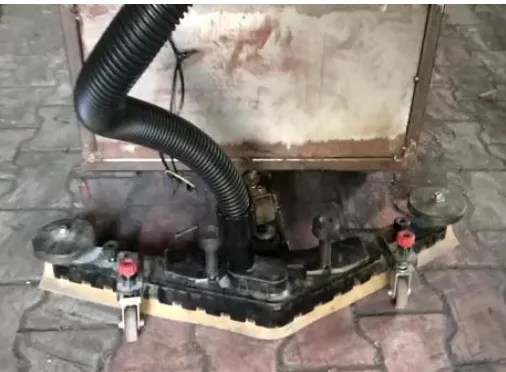
Initially the motor with speed reduction pulley and brush were assembled. Then this setup was fitted to the mounting bracket with the help of nut and bolts. A swinging arrangement is provided between the motor and bracket to ensure effective cleaning even on uneven floors.
Figure No 6: Initial picture of machine
4.7 Mounting of Vacuum Pump and Transformer
For vacuum pump mounting bolts were welded on tank and pump assembly was tightened with the help of nuts. Same arrangement is used for transformer assembly. The vacuum pump creates vacuum in tank as a result the dirty water collected at the squeegee is sucked into the tank through the hose.
Figure No 7: Mounting of vacuum pump and transformer
4.8 Mounting of squeegee arrangement:
Squeegee arrangement consists of two rubber blades connected to fibre frame having suction hole. Dirty water at back is sucked through this hole and discharged within tank due to vacuum created in it. This ready manufactured part is attached to machine bolt and nut assembly at bottom frame of machine. Bolt was welded to frame upside down through which adjustable height and pressure was achieved at squeegee arrangement. The dirty water from the floor is discharged into the tank through high quality vacuum hose attached to the squeegee. The hose is connected to the squeegee by special rubber connectors which ensure that there is no any leakage through joints.
Figure No 8: Mounting of squeegee arrangement
4.9 Powder coating of machine:
3643 we disassembled the parts and all bolts and plumbing
attachments were covered with tape
Figure No 9: Final Machine after powder coating
5. RESULTS & CONCLUSION
5.1 Results
Fig No 10. Comparison of no. of workers
Fig No 11. Comparison of Cleaning Time
5.2 Conclusion
1. Multifunctional floor cleaning machine is designed and manufactured using A.C. induction Motor and speed reduction mechanism. Manufactured machine is flexible and effortlessly operated. 2. The no. of workers required for cleaning has been
decreased from 8 to just 2. Hence wages of the workers are saved.
3. The time required for cleaning has been reduced to 1 hour, previously which was 4 hours.
4. Effective power given to the brush does number of cleaning tasks. The need of this project is satisfied and with the help of machine, cleaning of the floor can be done easily.
6. FUTURE SCOPE
With the advent of automatic spraying mechanism and utilisation of deliberate mechatronics systems, the machine can be metamorphosed into a fully automatic unit. By using a pump and timer-controlled mechanism the solution can be sprayed at regular intervals resulting in its efficient usage. Also, ultrasonic sensors with line and follower arrangement will make the machine autonomous. There is also a scope to suck the debris and small chips on the floor by utilising the vacuum pump or by creating a separate magnetic chip collection mechanism which can be attached at the front-end of the machine.
7. REFERENCES
[1] M. Ranjit Kumar, N. kapilan, ―Design and analysis of manually operated floor Cleaning machine‖, international journal of engineering and technology, 2278-0181, volume 4, Issue 04, April – 2015
[2] ―Theory of Machines‖, Rattan S.S. Tata McGraw Hill, 3rd edition.
[3] ―Design of Machine Elements‖, V. B. Bhandari, Tata McGraw Hill, Third edition
8 2
No. of Workers
Before
After
4 1
0 1 2 3 4 5
Cleaning Time
After
3644 [4] Dnyanesh Kamat, Vardhaman Ladage, Shardool
jawanjal, Bhagyashri Kadam, Rutuja Majgaonkar, ―Semi-automatic floor cleaning machine‖. International Journal of Design and Manufacturing Technology (IJDMT), Volume 8, issue 1, Pp.01-07