Institute of Manufacturing Metrology, Friedrich-Alexander-Universität Erlangen-Nürnberg (FAU), Erlangen, Germany
Correspondence to: A. Loderer ([email protected])
Received: 1 October 2015 – Accepted: 30 November 2015 – Published: 14 January 2016
Abstract. This article describes a new qualification concept for dimensional measurements on optical mea-suring systems. Using the example of a prototypical multi-scale multi-sensor fringe projection system for production-related inspections of sheet-bulk metal-formed parts, current measuring procedures of the optical system are introduced. Out of the shown procedures’ deficiencies, a new concept is developed for determining the orientations and positions of the sensors’ measuring ranges in a common coordinate system. The principle element of the concept is a newly developed flexible reference artefact, adapted to the measuring task of the fringe projection system. Due to its dull surface, the artefact is optimized for optical measuring systems, like the used fringe projection sensors. By measuring the reference artefact with each fringe projection sensor and aligning the resulting data sets on a digital reference model of the artefact, sensor-specific transformation ma-trices can be calculated which allow transformation of the sensors’ data sets into a common coordinate system, without the need for any overlapping areas. This approach is concluded in an automated measuring procedure, using alignment algorithms from commercial available software where necessary. With the automated measuring procedure, geometrical relations between individual measured features can be determined and dimensional mea-suring beyond the meamea-suring range of a sensor became possible. Due to a series of experiments, the advantages of the new qualification concept in comparison with the current measuring procedures are finally revealed.
1 Introduction
New production technologies, like sheet-bulk metal form-ing (Schaper et al., 2011), involve new challenges for di-mensional measurements of the manufactured parts. In the case of sheet-bulk metal forming, metrological requirements of a production-related inspection arise from the short cy-cle time, the complex and filigree geometry, and varying sur-face roughness due to the high, irregularly distributed form-ing forces (Merklein et al., 2012). The challenges of in-specting complex workpieces can be explained by consider-ing the “golden rule of measurconsider-ing metrology” (Berndt et al., 1968). In 1968 Georg Berndt developed a rule for selecting appropriate measurement systems. Therefore, the measure-ment uncertainties of the measuremeasure-ment systems have to be known. Following the recommendation of the golden rule, the measurement uncertainty should be at least less than a fifth, and better less than a tenth, of the tolerance width. If
this minimum requirement can be met, it ensures that the measurement results are accurate enough (Loderer et al., 2013). To achieve these requirements, a prototype of a multi-scale multi-sensor fringe projection system was developed, designed for a production-related environment (see Fig. 1).
The main parts of the prototype systems are three differ-ent types of fringe projection sensors with varying measuring ranges and resolutions (see Table 1).
Figure 1.Technical sketch of the idea without an overview sensor (left side) and realized set-up of the prototypical multi-scale multi-sensor fringe projection system (right side).
Table 1.Technical specifications of the fringe projection sensors.
Sensor type Available Measuring range in mm Resolution in µm Overview sensor
(GOM ATOS Compact Scan 2M)
1× 115×88×92 80 (mean point spacing) Detail sensor 1
(GFM MicroCAD 1.0 µm)
8× 13×10×3 17 (lateral); 1 (vertical) Detail sensor 2
(GFM MicroCAD 0.3 µm)
4× 4×3×1 2.5 (lateral); 0.3 (vertical)
eight detail sensors 1 and up to four detail sensors 2 (Loderer et al., 2015).
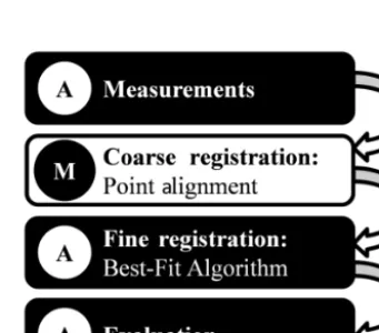
The process of gathering measuring results out of multi-scale data sets is divided into four main steps (see Fig. 2): firstly, measurements were done by all selected fringe pro-jection sensors automatically. Then the sensors’ data sets have to be transformed into a common coordinate system and combined into one holistic data set by a merging pro-cess. For this purpose the data sets are roughly aligned in a coarse registration by selecting corresponding points in each data set manually. Only if there is a large overlapping area with at least one significant feature can an automatic algo-rithm, e.g. presented in Shaw et al. (2013), be considered, but often this requirement cannot be met. In contrast to this for the following fine registration, various automatic algo-rithms are available. For the presented procedures, the best-fit algorithm of the commercial available Polyworks IMIn-spect 2014 software is used, which provides numerous set-tings for multi-data-set alignments. Next to point cloud data sets, polygonal models can also be aligned. The last step of the standard measuring procedure is the evaluation which can also be performed automatically. That procedure requires at least a small overlapping area. However, even if enough
cor-Figure 2.Automatic (A) and manual (M) steps of the standard mea-suring procedure.
responding points are available, the procedure is neither fast nor accurate enough to benefit from the high accuracy of the fringe projection sensors, as can be seen in the results pre-sented in Fig. 8.
Figure 3.Flat reference artefact for testing the qualification princi-ple.
system, a qualification concept, adapted to the properties of the prototypical multi-sensor multi-scale measuring system, has to be developed.
For the underlying research the shown measuring proce-dures have been selected as the most suitable approaches for further adaptations of the multi-scale multi-sensor fringe pro-jection system. Besides the explained four steps, there are other approaches for combining measurement data, e.g. pre-sented in Puente León and Kammel (2003), Komander et al. (2014) and Keck et al. (2014).
2 Qualification principle
To prove the basic idea of the qualification of optical multi-scale multi-sensor systems, a flat reference artefact was used (see Fig. 3). On the reference artefact, surface lines of differ-ing distances as well as radii of differdiffer-ing sizes were milled in, and thereby a unique surface structure was created (Kästner et al., 2013).
The measuring ranges of the considered optical sensors are significantly smaller than the artefact’s size. Setting up a multi-sensor measurement, the sensors’ measuring ranges are positioned onto a measuring object. Subsequently, the measuring object is replaced by the reference artefact. Each sensor now measures a part of the reference artefact’s sur-face and, due to the unique sursur-face structure, the position of each data set can be allocated. By a manually coarse reg-istration using point alignments and a following automati-cally fine registration, each data set can be aligned to a CAD (computer-aided design) model of the reference artefact. All necessary transformations to get the data sets in the correct positions can be expressed in transformation matrices. These matrices represent the sensor orientations and have to be saved. Replacing the reference artefact by a measuring ob-ject, the data sets of each sensor can be transformed in the correct position again by using the transformation matrices of the sensor. If the measuring range of a fringe projection
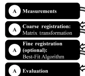
Figure 4.Automated (A) measuring procedure by using transfor-mation matrices.
sensor is changed, the qualification procedure has to be done once more.
With the flat reference artefact, a qualification field size of about 1800 mm2can be used which is equal to the surface size. Due to the flat design, only a lateral qualification is pos-sible, whereas all sensors have a similar vertical position.
The important advantage of the qualification principle is the loss of need for corresponding areas. Even data sets that do not overlap can be located correctly, and thereby dimen-sional measurements with optical multi-scale multi-sensor systems are enabled. Moreover, the time-consuming manual coarse registration has to be done only in the qualification procedure. Once all transformation matrices are available, the steps of the measuring procedure run automatically (see Fig. 4).
3 Flexible qualification concept
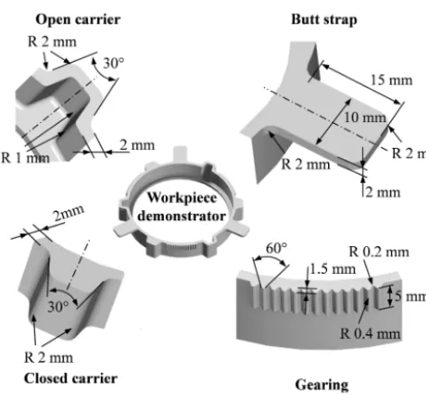
A crucial disadvantage is the flat shape of the reference arte-fact. Sheet-bulk metal-formed objects and the prototypical multi-scale multi-sensor fringe projection system designed for measuring often are of round shapes with varying diame-ters (see Fig. 5) (Merklein et al., 2015). With a flat reference artefact, the fringe projection sensors can only be qualified if their measuring ranges are positioned at the same height and oriented similarly. However, complex features like cylinders require differently positioned sensors with differing heights of their measuring ranges. The flat reference artefact is not capable of fulfilling these demands.
Figure 5. Workpiece demonstrator of sheet-bulk metal-forming processes with its differing sizes and shapes.
which are adjustable in the lateral and vertical directions. Thereby, measuring ranges do not have to be set up at the same height, but rather can be oriented freely. In order to op-timize the reference heads for optical measuring systems, the surfaces are glass-blasted to generate dull and very measur-able surface structures.
With the flexible reference artefact, a qualification field size of about 15 000 mm3can be used. Due to the vertical adjustment of the reference heads, a lateral as well as verti-cal qualification is possible.
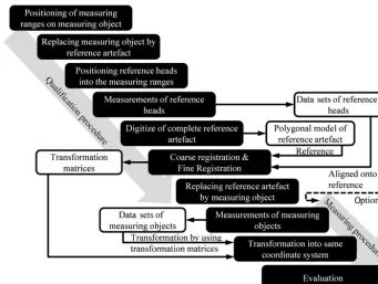
According to the qualification concept, ten main steps have to be considered when setting up a complete multi-sensor measurement (see Fig. 7). Firstly, the measuring ranges of the fringe projection sensors have to be positioned on the measuring object. Then the measuring object is replaced with the reference artefact and the reference heads are positioned into the measuring ranges. At least one reference head has to be inside the measuring range of each sensor. In the next step, measurements of the fringe projection sensors are trig-gered. To generate a reference polygonal model of the refer-ence artefact, it is digitized by using an optical sensor with a bigger measuring range. The quality of the measurement with the overview sensor is crucial for the qualification con-cept. The more accurate the overview sensor and the higher the quality of the digitization, the more accurate the qual-ification procedure’s result. In the shown experiments, the overview sensor is used to digitize the complete reference artefact.
Next the data sets of the fringe projection sensors are aligned to the digital reference polygonal model of the refer-ence artefact. From these alignments, transformation
matri-Figure 6.Flexible reference artefact adapted on sheet-bulk metal-formed parts.
ces for each data set are calculated, which express the orien-tation of each fringe projection sensor in a common coordi-nate system. The qualification procedure finishes by replac-ing the reference artefact with the measurreplac-ing object. With measurements of the measuring object, the following mea-suring procedure starts. Using the transformation matrices, the data sets of the fringe projection sensors can be trans-formed into the common coordinate system and combined into one common data set by a merging process. By repeating the measuring procedure, this qualification concept enables holistic dimensional measurements of complex features.
4 Comparison
To detect the advantages provided by the developed qualifi-cation concept, a comparison between the standard measur-ing procedure and the automated measurmeasur-ing procedure with the new qualification concept is worked out.
Figure 7.Complete steps for the qualification and measuring procedure.
Figure 8.Considered parameters for comparing the standard mea-suring procedure (standard) and the automated meamea-suring proce-dure (automated) with the new qualification concept (upper left cor-ner). Results for deviations of height (upper right corner), width (lower left corner) and comparison of needed time (lower right cor-ner).
standardized and only generates valid results when the two plains are parallel. Due to the use of a step height standard, the parallelism is ensured, and thus the Polyworks IMInspect 2014 approach is permissible.
In addition to the deviations of height and width of the qualified values, the time needed for performing all necessary steps is evaluated, too.
The results for the deviation of width show a significant difference between the automated measuring procedure with the corresponding new qualification concept and the former standard measuring procedure. Whereas the measuring re-sults, gathered by using the standard measuring procedure, are between 0.7 and 0.8 mm smaller than the qualified value, the deviation averages 0.42 µm using the automated measur-ing procedure. Considermeasur-ing the deviation of height, there is also a difference between both procedures. The deviation averages 5.0 µm for the automated procedure and−0.3 µm for the standard procedure. Although this difference seems to be small, its statistical significance is proven by using a Student’st test. However, focusing on the results’ distribu-tions, the reliability of the automated measuring procedure becomes obvious. The automated procedure provides con-tinuously the same value for results, which is caused by us-ing the same sensors’ transformation matrices for all ten data sets, whereas the values of the standard procedure are spread between 5 and 3 µm.
Comparing the duration needed for performing all re-quired steps, the automated measuring procedure takes less time. Even though the detected difference is only about 2 min, the automated process is of benefit the more data sets are used.
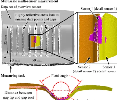
rep-Figure 9. Multi-scale multi-sensor measurement of a sheet-bulk metal-formed multiple gap structure (upper side) and the corre-sponding measuring task (lower side).
resents one completed data set. In contrast, the most time-consuming steps of the automated procedure are steps 1 to 3. These steps belong to the qualification procedure and in-clude the positioning and measuring of the reference heads, the digitalization of the reference artefact and the registra-tion of the reference heads’ data sets in order to calculate the transformation matrices. Once the matrices are available and a script for an automated measuring process is created, which is done in the fourth step, the needed time for the following data sets is significantly shorter.
5 Application
With the comparison of the standard and automated measur-ing procedures by usmeasur-ing the qualified step height standard, the advantages of the automated measuring procedure could be shown. In order to prove the advantages in a measuring task similar to a task for which the multi-scale multi-sensor fringe projection system was developed, the automated mea-suring procedure is applied in an inspection of a sheet-bulk metal-formed part.
With a process of the sheet-bulk metal forming, a multiple-gap structure is formed in DC04 sheet metal (see Fig. 9). In order to have precise data for evaluating and further improv-ing the process, a holistic detection of the relevant middle section of the multiple-gap structure is necessary. Such de-tection is not possible by using only one conventional fringe projection sensor with a large enough measuring range, e.g. the overview sensor. The smooth and thereby highly reflec-tive surface of the formed section in combination with the structure’s flank angle leads to missing data points and gaps
in the data set (Loderer et al., 2015). Moreover, due to small dimensions of the multiple-gap structure, the fringe projec-tion sensor’s resoluprojec-tion would be not accurate enough. Using only one fringe projection sensor with a smaller measuring range but instead an appropriate resolution, the whole rele-vant section cannot be detected at once.
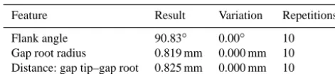
This conflict leads to a multi-scale multi-sensor measuring set-up, similar to the measurement of the step height stan-dard, where one side of the structure is detected by one sep-arate sensor of the type of detail sensor 2 and the gap root’s detection is done by a third, more accurate sensor of the type of detail sensor 1. In order to allow dimensional measure-ments of flank angle, gap root radius and distance between gap tip and gap root, a qualification procedure has to ensure a precise and also robust alignment of the three resulting data sets.
To evaluate the stability and robustness of the automated measuring procedure, one data set of each sensor is run through the procedure 10 times, again using Polyworks IMInspect 2014. This means each data set is aligned man-ually onto a reference data set of the reference artefact for a coarse registration, and subsequently a fine registration by Polyworks IMInspect’s best-fit algorithm is done. The result-ing transformation matrices were used to transform the data sets correctly in a common coordinate system and the fea-ture evaluation was done finally. Due to using the same data set for each sensor 10 times, the same results for the eval-uated features should always be calculated. If there are any variations, these can be clearly matched as deviations in the automated measuring procedure.
rota-sensor data set of the best-fit algorithm, the results for the considered features are also identical every time without any spread or deviation. In this manner the robustness of the au-tomated measuring process could be proven in a measuring task for which the multi-scale multi-sensor fringe projection system was designed. In a real inspection set-up, the man-ual registration step is necessary only once in the qman-ualifi- qualifi-cation process for allowing a subsequently fine registration. With the transformation matrices generated then, the data sets of the following measurements are aligned correctly and no manual interaction is required.
6 Conclusion
In this article a new qualification concept, optimized for op-tical multi-scale multi-sensor measuring systems, was intro-duced, which allows dimensional measurements of features larger than the measuring range of the optical sensor. The ba-sic principle was proven by a flat-shaped reference artefact using the example of a prototypical multi-scale multi-sensor fringe projection system. A unique surface structure of the reference artefact ensures that the measured data sets can be aligned on a polygonal reference model, and thus transforma-tion matrices for each fringe projectransforma-tion sensor can be calcu-lated. These matrices contain the positions and orientations of each sensor, expressed in a common coordinate system. Thereby the correct transformation of all measurement data sets in a common coordinate system is enabled in order to generate a holistic data set. The basic principle was trans-ferred to a flexible reference artefact, adapted on the shape of sheet-bulk metal-formed parts for whose inspection the prototypical multi-scale multi-sensor measuring system was designed. Together with the new qualification and measuring procedures, an automated and reliable measurement of com-plex workpieces is possible now. Comparing the new qualifi-cation concept with the former standard measuring procedure by setting up a series of experiments, the gathered advantages become obvious.
In order to test the automated measuring procedure, which contains the new qualification concept, a measuring task of a sheet-bulk metal-formed multiple gap structure was set up.
Research Foundation (DFG) for supporting the investigations in research project Manufacturing of complex functional components with variants by using a new metal forming process – Sheet-Bulk metal forming (SFB/TR 73; online: https://www.tr-73.de). In addition, special thanks should be expressed to Michael Harant of the Friedrich-Alexander-Universität Erlangen-Nürnberg for his contribution, as well as to Thomas Schneider, Daniel Gröbel, Philipp Hildenbrand, and Johannes Koch from the Institute of Manufacturing Technology of the Friedrich-Alexander-Universität Erlangen-Nürnberg, and to Michael Gröne from the Institute of Forming Technology and Machines of the Leibniz Universität Hannover.
Edited by: K.-D. Sommer
Reviewed by: three anonymous referees
References
Berndt, G., Hultzsch, E., and Weinhild, H.: Funktionstoleranz und Meßunsicherheit, Wissenschaftliche Zeitschrift der Technischen Universität Dresden, 17, 465–471, 1968.
Kästner, M., Hausotte, T., Reithmeier, E., Loderer, A., Ohrt, C., and Sieczkarek, P.: Fertigungsnahe Qualitätskontrolle von Werkzeug und Werkstück, Tagungsband zum 2. Erlanger Workshop Blech-massivumformung 101–118, 2013.
Keck, A., Böhm, M., Knierim, K. L., Sawodny, O., Gronle, M., Lyda, W., and Osten, W.: Multisensorisches Messsystem zur dreidimensionalen Inspektion technischer Oberflächen, Technis-ches Messen, 81, 280–288, 2014.
Komander, B., Lorenz, D., Fischer, M., Petz, M., and Tutsch, R.: Data fusion of surface normals and point coordinates for de-flectometric measurements, J. Sens. Sens. Syst., 3, 281–290, doi:10.5194/jsss-3-281-2014, 2014.
Loderer, A., Galovskyi, B., Hartmann, W., and Hausotte, T.: Mea-surement strategy for a production-related multi-scale inspec-tion of formed work pieces, Proceedings of the 11th Global Conference on Sustainable Manufacturing – GCSM 2013, 23– 25 September 2013, Berlin, 148–153, 2013.
Loderer, A., Timmermann, M., Matthias, S., Kästner, M., Schnei-der, T., Hausotte, T., and Reithmeier, E.: Measuring systems for sheet-bulk metal forming, Key Engineering Materials, 639, 291– 298, 2015.