~ 270 ~ WWJMRD 2017; 3(7): 270-276
www.wwjmrd.com Impact Factor MJIF: 4.25 e-ISSN: 2454-6615
Safarov Ismail Ibrahimovich DepartmentHigher mathematics, Tashkent chemistry – technological Institute, Tashkent, Republic of Uzbekistan
Akhmedov Maqsud Sharipovich DepartmentHigher
mathematics, Bukhara Technological Institute of Engineering, Bukhara, Republic of Uzbekistan
Ruziyev Tulqin Razzoqovich DepartmentPhisics, Bukhara State Medical Institute, Bukhara, Department of Informatics and Biophysics
Buronov Sunatullo Aslonovich DepartmentHigher
mathematics, Bukhara Technological Institute of Engineering, Bukhara, Republic of Uzbekistan
Correspondence:
Safarov Ismail Ibrahimovich DepartmentHigher mathematics, Tashkent chemistry – technological Institute, Tashkent, Republic of Uzbekistan
Influence of Elastic Waves on Parallel Cylindrical
Shells with Perfect Fluid
Safarov Ismail Ibrahimovich, Akhmedov Maqsud Sharipovich,
Ruziyev Tulqin Razzoqovich, Buronov Sunatullo Aslonovich
AbstractThe paper deals with the stress-strain state of parallel cylindrical tubes with a liquid. A formal solution of the problem of the diffraction of plane harmonic (longitudinal or transverse) and no stationary elastic waves on parallel circular cylindrical shells with a liquid enclosed in an infinite medium is constructed. The problem with the help of the integral Fourier transform with respect to time reduces the system of partial differential equations with respect to the coordinate. The field of stresses in the shells and their around in a finite distance between them is studied in detail. It is found that the ranges of the selected parameters with stresses and displacements on the shadow side of the first shell, increases somewhat in comparison with the case of one obstacle. The problem is solved in a bicylindrical coordinate system under the action of harmonic waves. An analytic solution is obtained in special Bessel and Henkel functions, as well as numerical results. Parametric analysis of the dynamic stress coefficient.
Keywords: Shell, Elastic Medium, Heaviside Function, Incident Wave, Fourier Transform, Cylindrical Tube, Liquid, Harmonic Waves
Introduction
Stationary diffraction of plane elastic waves in many connected bodies is considered in fundamental works. And his students: Golovchana V.T. And Cherevko M.A. [1, 2]. Here the following approach is used. We consider an infinite elastic body having n-cylindrical noncontacting parallel inclusions. In a plane perpendicular to the inclusion, n-systems of polar coordinates are chosen, the center of each of which coincides with the center of one of the inclusions. Further, the longitudinal and transverse potentials are represented as the sum of the Fourier series for each inclusion. In [3], Chen considered the solution of the particular problem of scattering of a plane P wave by two identical rigid fixed inclusions. The wave propagates along the center line. His solution is based on the method of multiple reflections. Diffraction of waves on circular obstacles in a half-plane was considered in [5], applying the addition theorem in the same way as in [6] and representing the Hankel functions in integral form. The main numerical methods are given in [6, 7, 8] for solving dynamical problems. It is known that numerical methods, in comparison with analytic ones, allow solving more complicated problems that are closer to the real working conditions of the design. Fotieva N.N. [4], using the solution of Sherman DI, developed a program for quasistatic calculation of two parallel panels. As in the case of a single pipe, the solutions of other authors that did not find application in this problem can be used to calculate the pipes laid in the embankment in several threads. This includes work to determine the stress-strain state in a plate weakened by a series of circular reinforced holes [11, 12, 13]
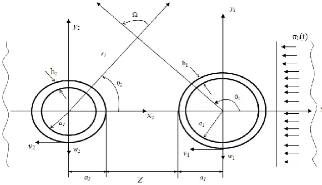
Fig 1:The settlement scheme
Statement of the Problem
An unbounded homogeneous isotropic elastic medium contains two cylindrical shells of radii аj (j=1,2), referred
to Cartesian (or cylindrical) coordinate systems (a1= a2). In the case of a sufficiently long cylindrical shell and an impact (directed perpendicular to its longitudinal axis), the environment and the lining are reduced to the plane problem of the dynamic theory of elasticity (Fig. 1). Mathematical formulation of the problem leads to the need for a joint solution, a system of differential equations of motion of the medium [14]
22
2 ;
2 ,
mn mn mn
u
u grad divu
t
(1)
and shell
2 2
2
0
1
2 2
0
2 2 2 2
0 2
0 2
2 2
0
(1 )
( , ),
(1 )
( , ).
j j j
i
j j
j
j j j
i
j j j j j
j
w v
v
a z t
E t
w w
v
c w h z t
E t
(2)
Where and - the Lame coefficients, defined by formulas
(1 2 )(1 ) E
, 2(1 )
E
v, w - tangential movement points of the middle surface of the shell; 0, , Е - respectively, the density of the Poisson
ratio and the modulus of elasticity of the shell material; 2 2/ 12 2, ( , ) ( 1, 2; 1, 2)
j j j кj
c h a z t к j
- external load
pressure; u- displacement vector;
- cylinder density;ij
- stress tensor; ij - tensor of deformations.
If the displacement vector is represented as a potential and a solenoidal part, then the wave equation in the cylindrical (r, , z) coordinate systems, respectively, have the form
ugrad rot
where ,
(0, 0,
z) - respectively, scalar and vectorpotentials of longitudinal and transverse waves; – the potential of longitudinal waves; The potentials of a function in Cartesian coordinate systems satisfy the following wave equations
2 2
2 2
2 2 2 2
1 1
0; Z Z 0,
р S
c t c t
(3) 2
- Laplace operator in polar coordinates; ср, сs - velocity respectively of the longitudinal and transverse waves. The problem under consideration is posed in cylindrical coordinate systems r,, z and reduces to the plane problem of the theory of elasticity. As unknowns, we use the
components of the displacement vector u ur, . The
cylindrical coordinate system is related to the Cartesian coordinate system by the following relations:
,
sin
cos
y
r
r
x
ds2=dr2+r2d2.The boundary conditions along the outer surface of the pipe are the condition for an ideal contact with the ground, the inner surface is free of loads. The boundary conditions ensuring the equality of the normal components of the fluid and shell velocities are
r2 u ( n) =+
t V
r a
, (4)
where V- fluid particle velocity; n- normal surface at r=a, w- radial movement of the shell. In order to completely close the formulation of the problem, it is necessary to add conditions at infinity to conditions (4)
0
u at R x2y2 filled with some radiation conditions.
For non-stationary problems, the causality principle is required as the radiation conditions, and in the medium there should be no displacements outside the region bounded by the leading edge of the waves from the oscillation sources.
1. The parameters of the incident wave and the shell along the generator of the cylinder are constant, therefore we assume that all functions describing the shell motion and the medium depend only on the angular coordinate , radial coordinates of time t. Change in normal voltage 0
on time is applied in the form
0( )t 0(1 t T/ ) , 0 t T; 0( )t 0 , 0 t T
, (5)or 0 0
( )t H t( x a)
c
amplitude; Т - Duration of wave action, H - Housed function. The initial conditions are zero.
The boundary conditions on the surface of the shell are applied as follows: the continuity of the radial and tangential changes in the soil and shell particles, i.e.
,
j r j
j j j j
w U v u
r a r a r a r a
(6) If the cylindrical cavity is not supported by a shell (cavity), then the boundary conditions take the following form:
- atra1:
( ) ( )
1 1
p s
rr rr
; ( ) ( ) 1 1 1 1
p s
r r r r
;
- atra2:
( ) ( ) 2 2 p s rr rr ; ( ) ( ) 2 2 p s rr rr
(7) The boundary conditions at infinity, i.e. At r :
0 .
First, we find a solution for a plane step of a particular wave. Stress tensor in general form
( )p ( )s
ij ij ij
where (р) - voltage when the incident wave, (s) - voltage
of the response waves. For each cylindrical shell there will be coordinates (x1y1) and (x2y2), but in a cylindrical system
(r1,1) and (r2,2). The transition from the Cartesian
coordinates to cylindrical next:
1 1 1 2 1 1
x r cos; y r sin; x1-br cos2
2, y1r sin2
2.In the polar coordinate system associated with the cylinder, the stresses and displacements in the incident wave r = a have the form:
0
0 1( 1) cos 2 0( ) / 2
r H z
(8)
0
0 0 0
0
0 0
0 2 0 0
0 1 1 0 2 0
1 1
1 0 0
( 1) sin 2 ( ) / 2
1( 1) cos 2 ( ) / 2
/ cos 2 ( ), V sin ( )
cos , =- / (1 )
r H z
H z
W C zH z zY z
C
z C t a a
where Н0(z) - unit function of Heaviside; 0 - voltage on
the front of a wave propagating in the direction; z, a - shell radius; С1 - expansion wave speed, 1 - Poisson's ratio; 1
- The density of the medium. Applying to the equations (7) and (8) the integral Fourier transform with respect to time
( ) ( ) exp( )
F i d
, 1( ) ( ) exp( )
2 F i dw
,where - time Fourier transform parameter; F() - feature image (t).
The wave equation (2) after application of the Fourier transform takes the following form:
2 2 2 2
1
2 2 2 2
1
/ / ( / ) 0
/ / ( / ) 0
i i i i p i
i i i i s i
x y c
x y c
for (ri,i) coordinates (2) can be written as:
2 2 2 2 2 2
2 2 2 2 2 2
/ (1/ ) / (1/ ) / ( / ) 0
/ (1/ ) / (1/ ) / ( / ) 0
F F F F
i i i i i i i i pi i
F F F F
i i i i i i i i si i
y y y y c
y y y y c
If you know the potential increments 1 and 1, Then it is
possible to determine the displacement of the environment of a cylindrical body
/ /
/ /
F F F
i i i i i
F F F
i i i i i
u x y
v x y
(9)
The solution of the wave equation (7) and (8) is expressed in terms of trigonometric and special functions:
( ) ( )
1 1 1 1 1 1
1
1
( ) ( )
2 1 1 1 1
2
1
( ) cos( ) exp( ) ( / ) cos ( 1)
( ) sin( ) exp( ) ( / ) sin ( )
i
F i
i n n r p
n
i
F i
i n n i p
n
B y i x d C k w c n
B y i x d D k kw c n
Here2 2 2 1/ 2
1 1
2 2 2 1/ 2
2 1
2
( / )
( / )
2(1 ) / (1 2 )
p p c k c R
Kn - Modified Bessel function, n - order [15].
Arbitrary constants В1, В2, Сn, n is determined from the
boundary conditions (4) and (5). To do this, you need to determine the voltage
(1) (1)
1 1 1 1 1 1
1 1
(1) (1)
1 1 1 1 1 1
1 1
(1) (1)
1 1 1 1 1 1
1 1
/ (2 ) ( ) ( )
/ (2 ) ( ) ( )
/ (2 ) ( ) ( )
c d
r r n n n n
n n
c d
n n n n
n n
c d
r n n n n
n n
C f r D f r
C S r D S r
C h r D h r
(2) (2)2 2 2 2 2 2
1 1
(2) (2)
2 2 2 2 2 2
1 1
(2) (2)
2 2 2 2 2 2
1 1
/ (2 ) ( ) ( )
/ (2 ) ( ) ( )
/ (2 ) ( ) ( )
c d
r r n n n n
n n
c d
n n n n
n n
c d
r n n n n
n n
C f r D f r
C S r D S r
C h r D h r
(10) Here , , , , ,C D C D C D
n n n
f S h expressed in terms of modified Bessel functions of the n-th order.
Arbitrary constants (Cn, Dn) is determined from the system
of algebraic equations.
The inverse transformation is carried out numerically by the Romberg method. Potentials, And the radial and tangential displacements from the envelope w and v for the incident wave are obtained using the Duhamel integral [9]
0 0
( ) ( )
t
i
u
u t dwhere u() - flat-stepped wave solution.
Discussion of numerical results. The improper integral (10) is calculated by the Romberg method [9]. For this, the improper integral is replaced by the integral [9]
1 ( ) ( , ) b a W W
l
f x dx(11)
the finite limits of which are chosen taking into account the nature of the spectral function. The integral (11) is calculated by the Romberg method, and the zero (n = 0) series of approximate values Т0/К=0,1,2,3.К - integral by
Wa,Wb into two equal parts
( )
0 1
0 1
k
( , ) 2 ( , ) ... ( , ) , 2
, i=0,1,2...2 2
k a b
k k
a b
i a km
W W
T f f f
W W
x i
With the help of Т0(к) Calculate n = 1,2,... K. A series of
approximate values of the integral Т(1):Fig.2
( )
( ) 1
1 1
(4 k ) / (4 1) k=0,1...k-n
k n k n
n n n
T T T (12)
The presented schemes are constant from the calculation
data
0 1
( ) k
f T с Stepl1 0, 02.
Fig. 2: Changing the hoop stress versus time.
For each fixed value of the computationf(1) was carried
out over the interval х by the formula (12) with k = 11. For some large valuesf (1) Repeated calculations with
increased accuracy gave corrections of less than 3%. Now let us see the interaction of the incident waves (1) and (3) with a cylindrical shell
-2 -7 -1
0 0 0
6 -2 0
1.0; 0.3; 6 . 10 , 3, 72 10 Е ,
5, 25 10 , ( 1, 2)
i i i j
i
a h a
E a T i
load Р0=2,38 10-5Е0 а-1, Ср1=1. 103а1с-1, сs1=4,4 102а1с-1,
load Р0=2,38 10-5Е0.
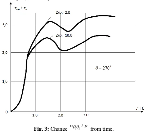
Fig. 3: Change 1 1/p from time.
Results of calculation of deflection ns w/h for the time t is shown in Fig3. The maximum deflections in the considered time interval are localized mainly in the angles corresponding to the angles =0о, 45о, Maximum tangential displacements in the values =90о and 270о. It can be seen that the action of seismic waves increases the
radial pressure of the surrounding medium. Calculations show (Fig. 2 and Fig. 3) that for fixed values of the amplitude and duration of the action, the incident wave increases with the acoustic rigidity of the surrounding deflection and earth to the first and second shells. Increasing the rigidity of the shell or its thickness leads to a decrease in deflections and an increase in effort. And with the increase in the thickness of the shell, the ring forces SCalculation is faster than bending moments and
bending moments are faster than lateral forces.
2. We consider the problem of the dynamic theory of linear elasticity, the effect of harmonic seismic waves on pipes laid in a high embankment in two strands and filled with an ideal compressible fluid. In this case, let us consider the case when the wave falls perpendicular to the axis connecting the tube centers, and to the longitudinal axis of these tubes. The calculation scheme is shown in Fig. The bicylindrical coordinate system is related to the Cartesian coordinate system by the following relations: x=(asin)/(ch-cos), y=(ash)/(ch cos), z=z (13) where: а - half distance between points =- и =. The problem is flat, we obtain the following Helmholtz equation in polar coordinates:
2 2 2
( cos ) ( ) ( ) 0
a ch v v k v
(14)
where
1
n=1
2 sin >0 sin
cos
2 sin <0
n
n
n
e n
ch
e n
(15)
Equation (14), after certain transformations, reduces to the form in
2
( )v ( )v(2kae) v0
(16) We seek the solution of (14) in the form of a series:
0
( ) cos ( ) sin
a b iwt
n n
n
v v n v n
(17)
Substituting (17) into (16) and equating the coefficients for the corresponding harmonics, we obtain the following ordinary differential equation:
" 2 2
(2 ) 0
n n
v kae n v
(18) The standard replacement
( ) ( )
n
v
z t , t=exp()we reduce (18) to the Bessel equation of the form
2 2 2 2
" +(4k a -n )z=0
t z tz (19)
which has a particular solution in the form of a cylindrical function z(2ake-), and the solution of the Helmholtz equation takes the following form:
0
(2 ) cos iwt
n n n
A Z ake n e
,
0
(2 ) sin iwt
n n n
B Z ake n e
. (20)
perpendicular to the y axis onto two underground pipes. The wave potential wave has the form
( )i Aei.x iwt
(21).
To represent (21) in the form (20), we write (21) with the aid of (12) in bipolar cylindrical coordinates.
( ) 2 exp( ) sin 1
iwt
i ik a e
Ae
(22)
Expanding the second factor of expression (22) into a Fourier series (complex form) and after small transformations, we obtain the final expression for the potential of the incident P wave:
( )
1 1
0
( ) cos
i i t
n n n
A J n e
(23)
where =2aexp( ).The remaining potentials (20), in analogy with (23), have the form:
( ) (1) (2)
2 2
2 0
( ) (1) (2)
2 2
2 0
( ) (1)
3 3
0
( ) ( ) cos ,
( ) ( ) sin ,
( ) cos .
r i t
n n n n
n
r i t
n n n n
n
r i t
n n n
C H D H n e
E H F H n e
G J n e
(24) The dynamic stress-strain state is expressed in terms of the potentials 1 and 2:( ) ( )
i i i
u ui ( )i (i) , 1
3 ( ) ( 3)
u
iw
(25)
2
i i 2 di 0,5 ( )sin 0,5i i( )
3 3 iw3 3 3
,
2
2 0, 5 0, 5 ( ) sin
i i
,
1, 2; / 2 .
i
e aSubstituting (24) and (25) in (8) we obtain the final solutions to the problems of the fall of the P and SV waves respectively on two underground pipes. Arbitrary constants An, Bn, Cn and others are determined from a
system of algebraic equations with complex coefficients [C]{q}={р}
where C is the determinant of (12x12) -order, the elements of which are the Bessel and Hankel functions of the 1 st second kind of the n-th order, q is the vector of a column of unknown quantities, and p is the vector of the right-hand side.
A system of algebraic equations with complex coefficients is solved by the Gauss method with the separation of the principal element. Dynamic stressed - deformed state in the case of a fall - shear wave on two underground pipes is also recorded in bipolar coordinates in the asymptotic form:
, ( ) , ( )
z z i z z i z
u w
u
u As boundary conditions, we use condition (23) and replace r = n. The final solution of the problem for the cases of the fall of the SH-wave into two tubes has the form:
(1)
1 0 1 1
0
(1) (2)
2 0 2 2
0
(1)
1 1 0 1 1 1
0
(1) (2)
2 2 0 2 2 2
( ) ( ) cos ;
( ) ( ) cos ;
( ) ( ) cos ;
( ) ( ) cos
iwt
z n n n n
n
iwt
z n n n n
n
iwt
rz n n n n
n
rz n n n n
u w J k A H k n e
u w B H k C H k n e
w k J k A H k n e
w k B H k C H k n e
0 (1)1 1 0 1 1
0
(1) (2)
2 2 0 2 2
0
;
( ) ( ) sin ;
( ) ( ) sin ;
iwt
n
iwt
z n n n
n
iwt
z n n n n
n
w n k A H k n e
w n B H k C H k n e
(27) Uncertain coefficients An,Bn,Cn is determined from theboundary conditions. Let us consider the definition of the dynamic stress-strain state of a cylindrical tube under the action of harmonic waves. To solve the problem, an addition theorem is applied. The addition theorems for cylindrical wave functions are derived in [4, 5, 6]. Let there be two different polar coordinate systems (rg,g) and
(rk,k) (Fig. 3), in which the polar axes are equally
directed. Pole coordinate k at q system will Rkq, kq, so
that equality
kg
i
g kg k
Z R e Z
(28) Then the addition theorem has the form:
( )
( )inq ( ) i n p kq ( ) exp( ),
n q n p kq k k k kq
p
b r e b R e Tpr ip r R
, ( )( )inq ( ) i n p kq ( ) exp( ),
n q n p kq p k k k kq
p
b ar e J R e b r ip r R
(29) Formula (28) makes it possible to transform the solution of the wave equation (1) from one coordinate system to another. Consider the calculation of an extended underground multi-thread pipeline for seismic action within the framework of the plane problem of the dynamic theory of elasticity. In this case, we investigate the case of stationary diffraction of plane waves on a series of periodically located cavities, supported by rings with an ideal compressible fluid inside. The solution of the problem is realized by the method of potentials. The boundary conditions have the form (8). The form of the incident potential will not change either. The potentials of the waves reflected from the tubes after the application of the addition theorem, and taking into account the periodicity of the problem, will have the form:( ) (1) ( )
1 1
1
0
( ) ( ) ,
r iwt in
n n n n
n
e A H r S J r e
( ) (1) ( )
1 1
1
0
( ) ( ) ,
r iwt in
n n n n
n
e B H r J r e
(1) (1) 1 1 0 1 ( ) ( ) , im imn p p n p n p
p m
S A E e H m e H m
(30) (1) (1) 1 1 0 1 ( ) ( ) , im imn p p n p n p
p m
Q B E e H
m e H
m
( ) (1) (2) ( )
2 1 2
0
( ) ( ) ,
i m w in
n n n n n
n
e E C H r D H r e
( ) (1) (2) ( )
2 1 2
0
( ) ( ) ,
i m w in
n n n n n
n
e E E H r F H r e
(31) and the velocity potential in the ideal form of a compressible fluid
( ) ( )
3 3
0
( ) ,
i m w in
n n n n
e E G J r e
(32)
Unknown coefficients An-Gn are determined by setting
(29) - (32) in (8). As a result, an infinite system of linear equations is obtained, which is solved by an approximate reduction method, provided that the relation
(1 cos ) 2
k
nThe general characteristic of the program is designed for multi-threaded pipes in the embankment for the case of a drop in seismic waves perpendicular to the axis passing through the pipe centers. The information entered contains the minimum required data: elastic characteristics (Е and ) soil embankments and pipes; Density of soil, pipes and fluids filling it; Internal and external pipe radii; The predominant period of oscillation of soil particles; Coordinates of the point where the VAT is located; Coefficient of seismicity. With the help of a special label, it is possible to calculate pipes filled with an ideal compressible fluid, or empty ones. The calculation of the cylindrical Bessel and Hankel functions is carried out according to known formulas. The solution of the system of linear equations is carried out by the Gauss method with the separation of the principal term.
Effect of distance between pipes. Table. 1 shows the
values of the coefficient
2 max( max rr / ( 2 ) 0)
The maximum radial pressure of the media (ground) on the pipes at different distances d between them in the event of a fall in longitudinal waves. In this case, the inner and outer radius of the pipes R0=0,8 m and R=1,0 m: The
predominant period of oscillation of soil particles is T = 0.2 sec. Soil Characteristics: Permanent Lame 1=8,9-
MPa; 1=4,34 MPa; density 1=1,74 Кn.sec 2
/m4. Pipe material characteristics 2=8690 MPa; 2=12930 MPa;
2=2,55 Кn sec2/m4.
Table 1: The value of the coefficient of dynamic concentration at different distances between the tubes for the case of longitudinal
wave incidence.
[1] D/d [2] 0,5 [3] 1,0 [4] 2,0 [5] 4,0 [6] max [7] 1,68 [8] 1,76 [9] 1,61 [10] 1,60
From Table: 1 it follows that first with increasing the distance between the pipes 0,5d/D1,0 coefficient max
slightly increases by 5%, and with a further increase d/D>1,0 Decreases more sharply by 10%. For d / D> 2.0, the value max stabilizes, i.e. Practically does not change,
with l4,0 close to the value max for a single pipe
according to calculations. Consequently, the mutual influence of reinforced concrete pipes of multiline stacking takes place with the distance between them d4,0D and leads to an increase in the maximum dynamic pressure of the ground on them compared to a single pipe. This effect of increasing the coefficient max is associated with the
imposition of waves reflected by several surfaces of
multicell pipes. In this case, the nonmonotonic increase in the coefficient max with a decrease in the distance
between the tubes, d / D is connected in our opinion with the phenomenon of interference superimposed after reflection of the waves. This phenomenon is extremely important for the practice of designing seismic underground multi-threaded pipelines. Allows you to choose the optimal distance between the pipes, at which the dynamic pressure during seismic action is minimal. For example, in Table 1, such a distance is d = 0.5D. It is known to note, for comparison, that in the case of static action, the reverse picture is observed: the pressure of the ground on multicell pipes is less than that of a single one. Table 2 shows the values max the maximum radial
pressure of the soil on the pipes in the event of a fall in the P- and SV-seismic waves at different distances d between the pipes. Analysis of the data of Table. 2 shows that for d/D<4.0, the coefficient values max For the P-wave and
SV-wave are as if in antiphase, i.e. At l / D = 1.0, the maximum seismic effect of the P-wave is 27% higher than for the SV wave, at d / D = 2.0 7% lower, and at d / D = 4.0 again higher, But only by 1%. At the same time, as the distance between pipes increases, the difference in these effects decreases and at d / D = 4.0 it practically disappears altogether. In addition, we note that when an SV wave is applied, the values max at different distances
between the pipes has a 2.5 times greater spread (up to 25%) than when the P wave is applied (up to 10%). Influence of fluid filling pipes. Table 3 shows the values of the coefficient max In the case of a fall of P-wave on
empty and water-filled pipes at different distances d between the pipes. The density of the liquid was assumed equal to 3=0,102 Кn sеc2/m4.
Table 2: Coefficient value max with seismic actions in the form
of P and SV waves at different distances d between the pipes. d/D max
P – wave SV - wave [11] 1,0 [12] 1,76 [13] 1,29 [14] 2,0 [15] 1,61 [16] 1,72 [17] 4,0 [18] 1,60 [19] 1,51
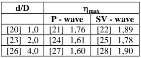
Table 3: Coefficient value max for the case of the fall of P-wave
on empty and water-filled pipes.
d/D max
P - wave SV - wave [20] 1,0 [21] 1,76 [22] 1,89 [23] 2,0 [24] 1,61 [25] 1,78 [26] 4,0 [27] 1,60 [28] 1,90
From Table 3 it follows that the presence of water in the pipes increases seismic effects on them compared to empty pipes. Obviously, this is due to the increase in the weight of the pipeline. The maximum dynamic pressure of the soil on the pipes is enhanced. For example: for d / D = 1.0, the difference in the values of the coefficient d/D=2.0-10%, with d / D = 4.0-19%. In addition, we note that the scatter of the coefficient values max at different distances d pipes
filled with water are less (7%) than for empty pipes (10%). Effect of shell wall thickness (pipes). Table 4 shows the values of the coefficient max for different thicknesses of
Table 4: Coefficient value max for different pipe wall
thicknesses t.
[29] d/D [30] 0,08 [31] 0,1 [32] 0,15 [33] 0,2 [34] max [35] 1,60 [36] 1,66 [37] 1,66 [38] 1,68
From Table 4 it follows that the range of wall thickness, practically does not affect the dynamic pressure of the soil. This, in all likelihood, is due to the fact that the wave does not penetrate the reinforced concrete pipe due to the sufficient rigidity of the pipe.
Conclusions
1. When exposed, the mutual influence of reinforced concrete pipes of multiline stacking takes place with a distance d> 4,0D between them and leads to an increase in the maximum dynamic pressure of the ground on them as compared to a single pipe (local resonance phenomenon) by 5-10%.
2. The phenomenon of local resonance manifests itself more strongly for seismic action in transverse waves than longitudinal waves.
3. The denser the soil of the embankment, the less seismic impact on underground pipes. The change in wall thickness and class of concrete practically does not affect the dynamic pressure of the soil on reinforced concrete pipes under seismic action. 4. Maximum dynamic earth pressure
max On pipes laidin two strings at a distance d<3.0D from each other, more than a single pipe. This excess reaches 15%. 5. The presence of liquid in the pipes, as a rule, increases
the pressure
max for a single pipe by 20% and for twothread pipes by 5-10%. The exception is densely packed pipes d=0, for which the pressure
max
decreases by 4%.References
1. Guz A. N., Golovchan V. T. Diffraction of elastic waves in multiply connected bodies. - Kiev: Science-Dumka, 1972.-254p.
2. Guz A. N., Kubenko V. D., Cherevko K. Diffraction of elastic waves. - Kiev: Science-Dumka, 1978.-308p. 3. Chen. Multiple scattering of elastic waves by parallel
cylinders. Applied Mechanics, World, No. 3, 1969, p. 151.
4. Fotieva N. N. Calculation of the lining of tunnels is not a circular outline, constructed in seismic regions. // Foundation of foundation and mechanics of soils. № 3, 1976. p.21-25.
5. Long C. F.. On the Completeness of the Lame Potentials / Acta Mechanica. Vol. III 1967.
6. Zitron N. R.. Multiple Scattering of Elastic Waves by Two Arbitraru Cylinders Journal of the Acoustical Society of America. Vol. 42, 1967
7. Avliyakulov N. N., Safarov I. I. Modern problems of statics and dynamics of underground pipelines. Toshkent, 2007, 306 p.
8. Okomoto Sh. Seismic stability of engineering structures. - Moscow: Stroyizdat. 1980.-342p.
9. Safarov I. I. Vibrations and waves in dissipatively inhomogeneous media and structures. - Tashkent: Fan. 1992. -250 p.
10. Pao Y. H. Mow C. C. The diffraction of elastic waves and dynamic stress concentrations. – N. Y.: Crane Russak and Co, 1973. 694 p.
11. Savin G. N. Stress distribution near the holes. - Kiev: Science-Dumka. 1968.-887 p.
12. Erzhanov N. S., Aitaliev J. M., Masanov Zh. K. Seismic stress of underground structures in an anisotropic massif. - Alma-Ata: Science. 1980. -211 p. 13. Alekseeva L. A. Diffraction of waves on a system of extensive underground mines of shallow location.: Bulletin of the Academy of Sciences of Kazakstan, 1987. № 2, p.46-52.
14. Watson G. N. Theory of Bessel Functions, Ch. 1-M., 1949. -798p.