Development of
Microcontroller-Based Inverter Control Circuit
for Residential Wind Generator
Application
Ahmad Firdaus Ahmad Zaidia, Riza Muhidab, Ahmad Mujahid Ahmad Zaidic,
Sazali Yaacobd, Nur Hidayah Ahmad Zaidie
a,bDepartment of Mechatronics Engineering, International Islamic University
Malaysia
a,dSchool of Mechatronic Engineering, Universiti Malaysia Perlis cFaculty of Engineering, National Defense University of Malaysia
eSchool of Material Engineering, Universiti Malaysia Perlis
*Corresponding email: [email protected]
Abstract
1 INTRODUCTION
Residential type wind generator normally is referred to small wind turbines of with capacity less than 3kW. They are normally installed at house lawn or some were even small enough to be mounted on the rooftops. They were also implemented by the consumer mainly as standalone system in remote areas not accessible to electricity grid but has high wind or part of hybrid system with photovoltaic to reduce the dependency on the electricity consumption bought from utility companies [1,2]. Due to generally low electricity consumption for residential use per household, a variable speed operation of residential type wind turbines can be implemented at areas where minimum speed of wind available between 3m/s to 7m/s. Within these speeds, voltage generated at a particular 500W wind generator permanent magnet type is around 18V to 30V [3]. One particular example of savings by consumer when using WECS: If a small wind energy system of 500W can operate for 8 hours minimum, the particular household can save about 40% from the usual electricity bills. Lately, there is an increasing trend to enable the WECS to supply excess generated energy back to the electricity grid. The public demand for this capability is high on residential type market segment particularly after introduction of net-metering policy in some countries like United States and Canada, where consumers were allowed to sold back to the utility companies to offset their consumption [1,2]. After all, promoting this policy could prove beneficial to both utility company and consumers as advantages of connecting a large number of these ‘stations’ to the grid are: 1. reduction of manufacturing cost to utility power stations; 2. increased reliability of the supply system and 3. reducing the consumer’s bill [2].
Inverter is actually one type of switched-mode power supply (SMPS) that transforms voltage from direct current (DC) to alternating current (AC). Normally it is used together with boost DC-DC converter and rectifier circuit in power converter topology to increase the low AC voltage generated at wind generator terminal to nominal AC load and grid voltage. This topology has been used in WECS particularly for permanent magnet type wind generator [6]. Conventional method to increase the AC voltage was to use step-up transformer. As a SMPS variation, it has advantage over the transformer for higher conversion efficiency of up to 95% compared to 40% for transformer and wider variation of input for fixed output [7]. This has made it more suitable choice for a WECS that strive to achieve fixed output voltage from variable input voltage due to variable wind speed.
Advances in microcontroller technology have made it possible to perform functions that were previously done by analog electronic components. With multitasking capability, microcontrollers today are able to perform functions like comparator, analog to digital conversion (ADC), setting input/output (I/O), counters/timer, among others replacing dedicated analog components for each specified tasks, greatly reducing number of component in circuit and thus, lowering component production cost. Flexibility in the design has also been introduced by using microcontroller through capability of flash programming/reprogramming of tasks [8]. Microcontrollers has been used in WECS particularly grid connected to perform various functions and task from instrumentation for sensing voltage, current and frequency of power delivered to grid to optimizing output power to sensing adequate wind speed for turning ON/OFF the system [1,9].
(1)
Where ρ is Air density (kg.m-3), ν
w is Wind speed (m/s), Cp is Coefficient of
performance, and A is Rotor rotational area (m2).
Tip Speed to wind Ratio (TSR), is important parameter that has relation with coefficient of performance, Cp as indicated by graph in Figure 1 [6,9,10] below:
Figure 1: Relationship of TSR and Cp
TSR is calculated by formula below [6,9,10]:
(2)
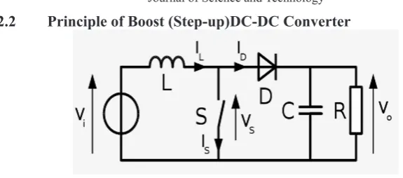
2.2 Principle of Boost (Step-up)DC-DC Converter
Figure 2: Boost converter schematic
Figure 2 [7] above is the basic schematic circuit of boost DC-DC converter. The basic principle of step-up (boost) DC-DC converter is as follows. When switch SW is closed for the time t1, inductor current rises and energy is stored in inductor L. If switch is opened for time t2, energy stored in the inductor is transferred to load through diode D1 and the inductor current falls. For a continuous current flow, waveform for the inductor current is as in figure. If large capacitor C is connected across the load, output voltage is continuous and becomes average value. Voltage across the load can be stepped up by varying duty cycle and the minimum output voltage is Vi when k = 0 [6].
The average output voltage is [7]
(3)
For a resistive load, ripple current is given by [7]
4)
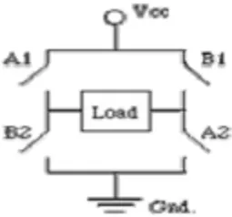
switched simultaneously at one half of a cycle while the switches B1 and B2 are simultaneously switched at the other half. Output of the circuit is positive and negative pulse voltage measured across the load. The load voltage varies accordingly and is in the range of +VCC and –VCC.
Figure 3: Standard H-Bridge circuit
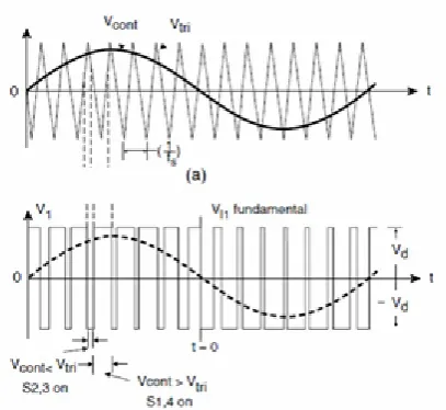
Figure 4: SPWM trigger signal generation method through bipolar switching. (a) Reference sine signal is compared with carrier sawtooth signal (b) Generated SPWM
trigger signal
3 METHODOLOGY
Figure 5 below describes the block diagram of the proposed system. The scope of this project is to design DC-AC inverter circuit and simulate performance of the inverter circuit to obtain desired voltage output of 240V, 50Hz where the scope of system design consists of:
a. Design of bridge rectifier at generator output.
b. Design of suitable boost DC-DC converter to step up from low wind voltage.
c. Design of H-bridge circuit to output AC from DC.
d. Design of microcontroller circuit and programming software to control duty cycle of H-bridge circuit.
Wind Turbine
Rectifier
circuit Boost DC-DC Converter MOSFET gate H-Bridge Circuit Microcontroll er PIC16F877A in trigger circuit
AC 18V -
30V DC 18V - 30V DC 240V
Load AC 240V PWM
Figure 5: Block diagram of proposed system
3.1 Bridge Rectifier Circuit Design
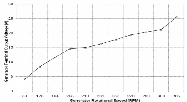
The voltage generated at terminal by wind generator will be AC waveform type of magnitude 10V to 30V depending on the wind speed as evidence in Figure 9 shows the wind generator manufacturer performance datasheet on voltage generated at various wind speed. A bridge rectifier circuit is connected at wind generator terminal to convert the waveform to DC. Figure 6 below shows the bridge rectifier circuit design.
Figure 6: Bridge rectifier circuit
3.2 Boost DC-DC Converter Design
is feedback and compared to set value equivalent to 240V. Then the carrier signal will be compared with the error signal to generate PWM signal. The duty cycle of PWM signal, k is determined by error gap between circuit output and set point. Output voltage is stabilized and regulated by minimizing ripple output voltage and current. Figure 7 below shows the design of Boost DC-DC converter in SIMULINK.
Figure 7: Design of Boost DC-DC converter in SIMULINK
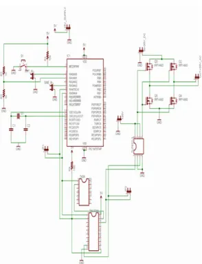
3.3 Design of Inverter Control Circuit
Figure 8: Inverter Control Circuit
The type of inverter implemented in the system is voltage-source-inverter (VSI) and the control technique implemented in the system is Sinusoidal pulse-width modulation (SPWM)[7]. Using this technique, the microcontroller PIC 16F877A is used to generate the required PWM train of pulses to drive and switch on the H-bridge MOSFET transistors.
out-put of the comparator will represent the desired PWM. A pulse signal which the frequency was synchronized with sine was generated by the PIC as control pulse. The pulse will be distributed to two channels where one of it is inverted. The PWM pulse train and control pulses signal were then fed into Tri state buffers SN74244 Data Transceiver. The output is two channels of PWM train pulse switching ON and OFF at 180 degree out of phase. The two signals are then connected to necessary conditioning elements to be able to switch ON the MOSFET transistors at the H-bridge. Now the generated PWM will switch two diagonal MOSFET transistors of the H-bridge simultaneously at one of the two halves and the other two diagonal transistors at the other half. The out-put of H-bridge is connected the load through LC filtering to achieve desired AC sinusoidal waveform.
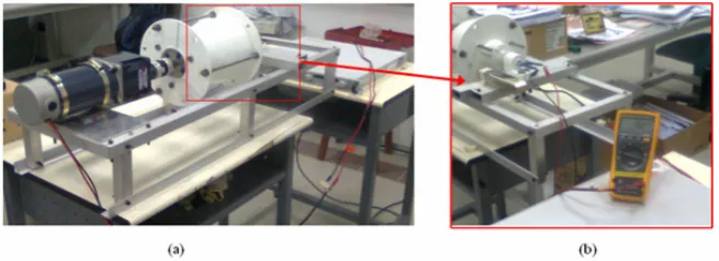
3.4 Experiemental Rig and Hardware Setup
Figure 10: (a) Experimental rig for wind generator simulator; (b) Turbine rotational speed and generator terminal output measurement
Figure 12: 500W Voltage generated at terminal of wind generator simulator rotated at different speed.
4 RESULTS AND DISCUSSION 4.1 Simulation Results
The rectifier circuit and DC/DC boost converter were simulated using MATLAB SIMULINK software and tested at different input voltage from 18V to 26V to simulate different wind speed condition. As shown in figure 13, rectifier circuit convert the AC voltage generated at the wind generator terminal to continuous DC voltage. There is however dropping of 2V at this stage.
Figure 13: Simulated output of rectifier circuit.
Figure 14: Simulated output of Boost DC-DC Converter
in two channels.
Figure 18: Simulated SPWM trigger signal in two channels in SIMULINK
Figure 20: Simulated output voltage of inverter circuit after LC filtering
4.2 Experimental Results
Figure 21: SPWM Trigger signal generated by microcontroller-based prototype board
Figure 23: Voltage across resistive load at output of the prototype H-bridge circuit
Figure 24: Voltage across resistive load after LC filtering at output of the prototype inverter circuit
5 CONCLUSION
output voltage has been successfully generated. However the inverter prototype board could invert voltage up to 12V DC before stability problem occurs. Inclusion of soft-starter element across the MOSFET terminal at H-Bridge circuit was recommended in order to solve this problem.
REFERENCES
[1] Razzaqul Ahshan, “Control System for Small Induction Generator Based Wind Turbines”, M.Eng. Thesis, November 2007, Memorial University of Foundland, Canada
[2] Beck, Y.; Bishara, B.; Medini, D., "Connecting an alternative energy source to the power grid by a DSP controlled DC/AC inverter," Power Engineering Society Inaugural Conference and Exposition in Africa, 2005 IEEE , vol., no., pp. 120-124, July 11-15, 2005
[3] Hummer 500W Wind Turbine Operation Manual by Anhui Hummer Dynamo Co. Ltd
[4] Malaysian Standard MS406:1996 ICS29.020 Specification
for Voltages and Frequency for Alternating Current Transmission and Distribution (Second Revision) by SIRIM 1996
[5] IEEE Standard 519-1992
[6] Jamal A. Baroudi, Venkata Dinavahi, Andrew M. Knight, “A review of power converter topologies for wind generators”, Renewable Energy Volume 32, Issue 14, November 2007, Pages 2369-2385 [7] Muhammad H. Rashid, Power electronics: circuits, devices, and
applications, 3rd Ed., 2004, Pearson/Prentice Hall.
[8] PIC16F87XA Datasheet – 40 Pin Enhanced Flash Microcontroller by Microchip
[9] Arifujjaman, Md.; Iqbal, M.T.; Quaicoe, J.E., “Maximum Power Extraction from a Small Wind Turbine Emulator using a DC - DC Converter Controlled by a Microcontroller”, Electrical and Computer Engineering, 2006. ICECE '06. International Conference on , vol., no., pp.213-216, 19-21 Dec. 2006