JEEECCS, Volume 2, Issue 6, pages 25-35, 2016
Hierarchized Distributed Control System for a
Gas Processing Unit
Marian POPESCU
Automatic Control, Computers and Electronics Department Petroleum-Gas University of Ploiesti
Ploiesti, Romania [email protected]
Abstract – The paper presents a study regarding the complex problems associated with the hierarchical and distributed control of a gas processing unit. This unit consists of three separation columns, and for this train of distillation columns a hierarchized distributed control system with three levels is proposed. First hierarchical level is dedicated to conventional control, second level is associated with advanced control and third level is the optimal control level. The levels of the hierarchical control systems for each column are characterized and the proposed solutions are studied through simulation.
Keywords-hierarchical system; distillation column; feedforward control; decoupling; internal model control; optimal control
I. INTRODUCTION
The process of distillation is probably the most used operation of mixtures separation into pure components or components mixtures. In chemical and petrochemical industry approximately 95% of the separation processes are performed using distillation, the units in which the distillation takes place consuming nearly 3% of the total energy consumption in the world [1, 2]. The economic objective of distillation is to obtain more valuable products relative to the mixture being processed. Because the products values depend directly on their quality, the assurance of the quality specifications is of great importance in distillation columns operation. Also, the operation methods must provide certain production and profit [3].
The distillation process complexity, given by its dimension and the multiple objectives that must be achieved, involves a high effort in finding the proper control solutions. The important problems of distillation control consist in: the control loops interactions; the process nonlinearities; the time variation of process parameters; the slow dynamics of the process; the large load changes which may occur. The solutions to these problems could include feedback control, feedforward control, multivariable control or optimal control strategies [4]. The complexity of the control problem can be addressed through a hierarchical approach by: specifying the control objectives with different time scales, modelling the process from abstract to detailed, selecting the controlled and manipulated variables, enabling the configuration of control structures [5].
The evolution of the distillation processes and the targets that must be achieved in their operation, as well as the development of the automation equipment, imposed the hierarchical and distributed structures in the control of these processes.
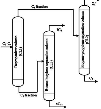
In this paper, the object of the investigations regarding its control is a gas processing unit which takes part from a catalytic cracking plant, and represents practically a train of (three) distillation columns, presented in Fig. 1.
Figure 1. Simplified structure of the gas processing unit.
As it can be seen in Fig. 1, the depropanizer column separates the C3-C4 fraction. The top product consisting mainly in propane and propylene is dried and then sent to the propane-propylene separation column (PPSC). The bottom product of the depropanizer represents the feed for the butane-butylene separation column (BBSC). The propane-propylene separation column separates the C3 fraction, with propylene at the top and propane at the bottom. The butane-butylene separation column separates the
C4 fraction, the top product contains mainly isobutane and isobutylene, and the bottom product is composed of nbutane, cis- and trans-butylene.
proposed hierarchical system for the investigated gas processing unit. In section 3 is described the control system for the C3-C4 separation column, the main contribution being the proposal of an objective function at the optimal control level which calculates the optimum values of the set-points for the flowrate and boilup flowrate control systems thus ensuring the best separation. Section 4 emphasizes the contributions regarding the hierarchical control system with three levels for the propylene-propane separation column, namely, the implementation of a feedforward control system at level 2, and the proposal of an objective function at level 3 which ensure the recovery of the most valuable component with low energy
effort. In section 5 is presented the hierarchical control system for the butylene-butane separation column. The main contributions regarding this system refer to the proposal of a nonlinear decoupler which calculates automatically its parameters and type, the use of internal model controllers for the two concentrations at the second hierarchical level and the proposal of an objective function at the third hierarchical level.
II. PROPOSED HIERARCHICAL SYSTEM
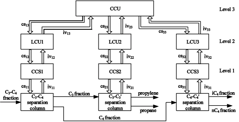
The general structure of the proposed hierarchical system for the gas processing unit consists of three hierarchical levels, as it can be seen in Fig. 2.
Figure 2. The proposed hierarchical system: CCU – central control unit; LCU – local control units; CCS – conventional control systems; csij
– control signals; ivij – information variables.
First hierarchical level is associated with conventional control, with each CCS containing the controllers associated with basic control for each distillation column, which refers to the control of the following parameters: column top pressure, levels from the reflux drum and column bottom, reflux flowrate and bottom product flowrate.
The second hierarchical level is dedicated to advanced control (feedforward, IMC etc.), the control functions from this level being fulfilled by the local control units (LCU). The third hierarchical level is associated with optimal control, and refers to the fulfillment of technical and economic objectives, this level’s functions being implemented in the central control unit (CCU).
The structure from Fig. 2 is partially distributed, the process being considered consisting of subprocesses (the three distillation columns), this partition being given by both geographically, but mostly functional criteria. This control system is hierarchized on vertical and distributed on horizontal within each level.
In this paper, the hierarchical levels were studied through simulation in SIMULINK®. For each column, the first hierarchical level is implemented using a
nonlinear model [6, 7, 8] based on material balance (total and component) (relations (1-2)), equilibrium equations (relation (3)), hydraulic delays associated to the vapor and liquid transport phenomena etc.
j j j j j j
j L V V L FV FL dt dM
1 1
, ) ( 1 , 1 1 , 1 , , ij j ij j j i j j i j FV i j FL i j ij j y V x L y V x L y FV x FL x M dt d j j
yij xij/(1(1)xij)
where: Mj – liquid holdup of j tray; FLj, FVj – external liquid and vapor flowrates of j tray; Lj, Vj – liquid and vapor flowrates leaving j tray; xi,FLj– concentration of
component i in external liquid feed of j tray; yi,FVj –
concentration of component i in external vapor feed of
The used model is for a binary distillation column, so the two multicomponent columns (depropanizer and butane-butylene separation column) were treated as pseudo-binary ones, the PPSC being implicitly binary.
The dynamic simulations of the three columns was performed using a simulator developed in SIMULINK around the nonlinear model previously described. The simulator associated to the columns has the structure from Fig. 3.
Figure 3. Structure of the column simulator.
It can be observed that the structure of the simulator is based on closing the control loops associated to the levels in reflux drum and column bottom. Given that the studied columns control structures are LV and LB, the flowrates for level control are distillate D and bottom flowrate B or boilup flowrate V, respectively. Thus, the process model inputs are: the flowrates used as control agents (reflux flowrate L and V or B), flowrates used for levels control (D and B or V), the two disturbances (feed flowrate F and feed concentration xF), fraction of liquid in feed (qF). The outputs of the model are concentrations xD and xB, and the liquid holdups for reflux drum and column bottom (MRD and MB).
In the following sections the hierarchical systems for each column are described.
III. THE HIERARCHICAL CONTROL SYSTEM FOR THE
C3-C4 SEPARATION COLUMN
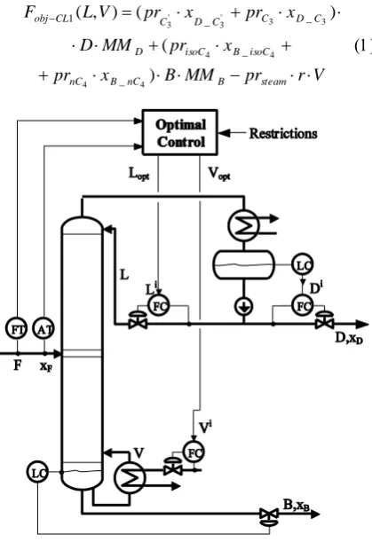
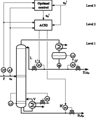
The control system associated with the C3-C4
mixture separation column is presented in Fig. 4 and consists of the conventional automation level (LV
control structure [9]) and the optimal control level. The LV control structure means that L (reflux flowrate) and V (boilup flowrate) are the control agents for this column used for control of the two concentrations: xD – the concentration of the light component (propane-propylene mixture) in the top product, and xB - the concentration of the light component in the bottom product.
The optimal controller implements an objective function presented in (1) [10].
V r pr MM B x pr x pr MM D x pr x pr V L F steam B nC B nC isoC B isoC D C D C C D C CL obj ) ( ) ( ) , ( 4 4 4 4 3 3 ' 3 ' 3 _ _ _ _ 1
Figure 4. Control system for C3-C4 separation column.
The notations used in (1) signify:
'
3
C
pr - price of the propylene from the top of CL2 column [lei/t];
3
C
pr - price of the propane from the bottom of CL2 column [lei/t];
4
isoC
pr - price of the isobutane-isobutylene mixture from the top of CL3 column [lei/t];
4
nC
pr - price of the nbutane-(cis+trans)-butylene mixture from the bottom of CL3 column [lei/t];
prst - steam price [lei/t];
'
3 _C D
x - percentage representation of propylene concentration in the light product from the top of CL1;
3 _C D
x - percentage representation of propane concentration in the light product from the top of CL1;
4 _isoC B
x - percentage representation of isobutane-isobutylene concentration in the heavy product separated at the bottom of CL1;
4 _nC B
x - percentage representation of nbutane-(cis+trans)-butylene concentration in the heavy product separated at the bottom of CL1;
MMD - molar mass of propylene-propane mixture [kg/kmole];
MMB - molar mass of C4 fraction [kg/kmole]; D - distillate flowrate for CL1, D = V L
[kmole/min];
B - bottom product flowrate for CL1, B = F D
= F + L V [kmole/min];
The objective function designates a (theoretical) profit obtained from selling of the products from the CL2 and CL3 columns, from which is deducted the costs associated with utilities (steam, in this case) from CL1 column. The restrictions refer to the variables L
and V.
In order to calculate the objective function, it was developed a MATLAB® script which contains: a process model; the values for products and steam prices, F, MMD, MMB and r; the relations for '
3 _C D
x ,
3 _C D
x , xB_isoC4 and xB_nC4 ; the expression of the
objective function from (1).
The optimization problem is multidimensional with constraints and the solving starts from an initial estimation of the solution.
In Fig. 5 is shown a 3D representation of the objective function on the domain imposed by restrictions.
Figure 5. Representation of the objective function.
The result of the objective function maximization is the pair of control signals [LoptVopt] = [13.2 17.5] [kmole/min] which ensure a separation with xD = 0.9934 mole fr. and xB = 0.0057 mole fr., the profit being of tens of thousands of lei/h.
The hierarchical control system presented in Fig. 4 was simulated in SIMULINK®. The outputs of the optimal controller (Lopt and Vopt) represent (practically) the set-points for the reflux flowrate and boilup flowrate control systems from the first level.
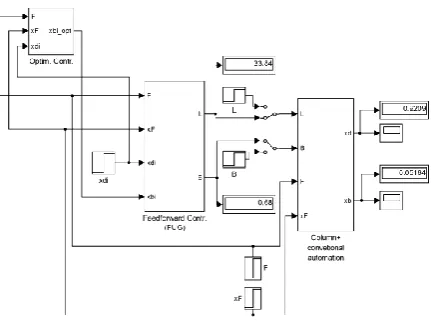
Figure 6. Simulation scheme for C3-C4 separation column
hierarcahical system.
In Fig. 6 it is presented the simulation scheme of the hierarchical control system associated to the C3-C4
separation column. The solver uses Runge-Kutta algorithm with variable integration step, and the interval of integration is [0…300] min.
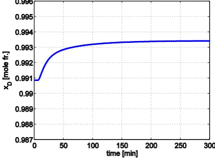
Fig. 7 and 8 present the time evolutions of concentrations xD and xB to modifications of set-points
Li and Vi from current values 12.15 kmole/min and 16.44 kmole/min to optimal values calculated by the optimal controller, 13.2 kmole/min and 17.5 kmole/min respectively.
Figure 7. xD evolution to Li and Vi changes.
Figure 8. xB evolution to Li and Vi changes.
The responses from Fig. 7-8 demonstrate that the application of the optimal set-points for L and V leads to an increase of xD concentration and a decrease of xB
concentration thus ensuring an improvement in separation, which means that the top product of the column contains very little of the butylene-butane mixture and the bottom product contains very little of the propylene-propane mixture.
IV. HIERARCHICAL CONTROL OF THE PROPANE
-PROPYLENE SEPARATION COLUMN
The control system associated with the propane-propylene separation column is presented in Fig. 9 and consists of the conventional automation level (LB
The LB control structure means that L and B are the control agents for this column, the top concentration being controlled using the reflux flowrate (L) and for the bottom concentration control is used the bottom product flowrate (B). The disturbances associated with this column are feed flowrate (F) and feed concentration (xF).
Figure 9. Hierarchical control system for CL2 column.
The second and third hierarchical levels are characterized in the following.
A. Advanced control level for PPSC
From studies of the propane-propylene separation column [11, 12] it was observed that the two disturbances of the column (F and xF) have an important effect on concentrations xD and xB. Thus, at the second level of hierarchical control is implemented a feedforward control system, the block diagram of the control system being presented in Fig. 10.
Figure 10. Block diagram of first and second hierarchical levels.
The control mathematical model is based on Fenske-Underwood-Gilliland (FUG) relations [13, 14, 15, 16] which take into account total and component material balance, minimum number of theoretical trays, minimum reflux ratio and relative volatility.
At the second hierarchical level the set-points are the concentrations of the light component in distillate and in the bottom product (xDi
and xBi
), the disturbances are F and xF, and the outputs are set-points (Li and Bi) for the reflux flowrate and bottom product flowrate control systems from the first hierarchical level.
First two hierarchical levels were simulated in SIMULINK® (Fig. 11).
Figure 11. Simulation scheme of first two hierarchical levels for PPSC.
The feedforward model (FUG) implemented at the advanced control level is a steady-state one, and using first order differential equations a dynamic component was added to the model.
The feed flowrate (F) presents more important and frequent variations than the feed concentration xF. Taking into account this aspect resulted from analysis of data from a real column, the following results refer to the system behavior only to F changes.
In Fig. 12-15 are presented the evolutions of the two concentrations to modifications of F, in two cases: without and with compensation.
Figure 12. xD evolution to a 2.5% increase of F.
Figure 14. xD evolution to a 5% decrease of F.
Figure 15. xB evolution to a 5% decrease of F.
Analyzing the responses from Fig. 12-15 it can be observed that the feedforward controller compensates with success the effect of the disturbance feed flowrate on the two concentrations, these results being confirmed also by [11, 12].
B. Optimal control level for PPSC
The two products separated at this column have different quality specifications. As the top product specification is fixed (rigid) with xDi
= 0.92 mole fr., the quality specification of the bottom product is xBi
[0.01…0.1].
The determination of the optimum value of the bottom product specification (xBi
) takes into account the recovery of the most valuable product (propylene) with as low as possible energy effort. This requirement can be implemented with the following objective function
) (
) (
2
B L F r pr
x B p MM x
F
st
i B B
i B CL obj
where: prst is steam price, [lei/kg]; p- price difference between propylene and propane, [lei/kg]; B - bottom product flowrate, [kmole/min]; MMB - molar mass of propane, [kg/kmole].
The product r (F + L B) represents the steam flowrate, with r the ratio between the vaporization latent heat of the propane and condensation latent heat of the steam [kg/kmole].
The optimum value of xBi
is obtained by minimizing the objective function from (2), based on the values of disturbances F and xF and set-point xDi, which are the inputs of the optimal control level, as it can be seen in Fig. 9.
The controller from this level contains the objective function, a control mathematical model of the process and an algorithm for determining the optimum (e.g. golden section algorithm).
A representation of the objective function is shown in Fig. 16.
Figure 16. Objective function representation.
By minimizing the objective function, the optimum value of the set-point for the bottom product concentration was obtained, xiB_opt = 0.0526 mole fr., a
value which ensure the recovery of the most valuable component with low energy effort.
Figure 17. Simulation scheme of the hierarchical control system with 3 levels for PPSC.
The system with three hierarchical levels (the column with conventional control at level 1, the feedforward controller at level 2 and the optimal controller at level 3) was simulated in SIMULINK® (Fig. 17), and the time response of the concentration xB
Figure 18. xB evolution to the change of xBi.
From Fig. 18 it can be observed that the concentration xBis brought to the set-point imposed by the optimal controller.
V. HIERARCHICAL CONTROL OF THE BUTANE
-BUTYLENE SEPARATION COLUMN
The hierarchical control system for the butane-butylene separation column is presented in Fig. 19 and has three levels: the conventional automation level (LB
control structure [9]), the advanced control level (ACS3) and the optimal control level.
As in the PPSC case, the LB control structure means that L and B are the control agents for the control of the two concentrations (xD – concentration of isobutene-isobutylene mixture in the top product, and xB - concentration of isobutene-isobutylene mixture in the bottom product). The disturbances associated with this column are feed flowrate (F) and feed concentration (xF).
Figure 19. Hierarchical control system for CL3 column.
The second and third hierarchical levels are characterized in the following.
A. Advanced control level for BBSC
Distillation columns are multivariable systems which present crossed interactions that cannot be neglected and can create control difficulties. The LB
control structure associated with BBSC can be considered a 2x2 system with L and B as inputs and xD
and xB as outputs.
From studies on this column it was observed that L
influences not only the top concentration but also the bottom concentration, and B has an effect on xD not only on xB. Consequently, a decoupler must be used in order to diminish or eliminate these crossed interactions.
The method used in this paper is general, the decoupler having a standard structure which can be implemented in four versions, one of these versions being presented in (3) [17].
1 1
1 1
) (
21 21
12 12
1
s T
K
s T
K
s G
d d
d d
D
The form from (3) is used when the direct channels are faster than the crossed channels. The other versions are similar, with forms depending on the process dynamic characteristics, and having the following properties: the gain on the direct channels is 1 and at least two of the four channels are static.
The decoupler gains (Kd) are obtained from the steady-state decoupling condition and the time constants (Td) are calculated, for each version, as differences between the process time constants on the corresponding channels.
The first step in the decoupler design was the determination of the process gains (Kp) and the transient times (Ttr) for step changes of the control agents L and B. The process time constants (Tp) are obtained as Ttr / 4 [17].
Figure 21. Tp variation according to B variation on B xD channel. Fig. 20-21 present two examples of dependencies of Kp and Tp on L and B variations.
All dependencies of Kp and Tp according to L and B
variations were approximated with regression functions with different degrees.
The next step in the decoupler design was to develop a MATLAB® function which automatically compute the values of Kp and Tp depending on current values of the inputs, through interpolation (if the variations of the inputs are in the already considered domains) or using the previously determined regression relations (if the inputs variations are outside the considered domains). This function also calculates the decoupler parameters (Kd and Td) and type, depending on the process channels dynamics. According to the obtained decoupler type, there are implemented the previously mentioned four versions of the decoupler. Fig. 22 synthesizes the described algorithm.
Figure 22. Decoupler synthetic representation.
Fig. 23-24 present some results obtained by simulating the system composed of the decoupler and the BBSC, system which has as inputs the control signals c1 and c2 and as outputs the two concentrations
xD and xB.
Figure 23. xB evolution to a 10% increase of first input.
Figure 24. xD evolution to a 3% increase of second input. Fig. 23-24 emphasize the beneficial effect of the decoupler on the crossed channels.
The main advantage of the decoupling is the possibility to consider the concentration multivariable control system as two independent monovariable control systems, as it can be seen in Fig. 25.
Figure 25. Concentration control system.
The decoupler together with the two concentration controllers (ACxD and ACxB) are implemented at the
second level of the hierarchical system for BBSC presented in Fig. 19. ACxD and ACxB are feedback
internal model controllers.
For the model based standard control method used in this study, the controller is designed so that the control system response to step set-point is the same as the process step response. An important property of this method is that for unit step set-point the control signal is also a step function [17].
Figure 26. The standard internal model control system: yi –
set-point; e – error; c – control signal; d – disturbance; y – output; GC (s) – internal model controller transfer function; KC – controller
gain; GM (s) – model transfer function; KM – model gain; GP (s) –
process transfer function.
The standard value of the controller gain KC is 1 [17].
The model of a stable and overdamped process, with gain Kp, transient time Ttr for step input, and dead-time Tm, can be like the one from (4) [17].
2
) 1 ( ) (
s T
e K s G
M s T M M
m
Most often, practical applications use a model gain
KM equal with process gain Kp, and the model time constant TM as the sixth part of transient time Ttr [17].
Because the presented method can be applied only to overdamped processes, and the response of the studied system on channel c1 xD is underdamped with overshoot (as presented in Fig. 27), in series with the process a filter was used
1 1 ) (
s T s G
f
f
Figure 27. xD evolution to c1 changes.
The filter time constant Tf was determined so that the process response to be overdamped, and the best obtained value was 40 min.
The concentrations control system were simulated in SIMULINK®, the simulation diagram being presented in Fig. 28. The integration interval is [0…1000] min, and the solver uses ode45 function which implements Runge-Kutta algorithm for solving systems of differential equations.
Figure 28. Simulation scheme of the concentrations control systems.
At this point, the control system for xD
concentration can be studied using the standard internal model control method. The tuning parameters for the controller of this system were determined to obtain a response without overshoot and with adequate transient time and a control signal close to a step form. The best tuning parameters were KC1 = 1, KM1 = 0.4,
TM1 = 30 min. and Tm1 = 10 min., the system response for a step change from 0.9578 mole fr. to 0.97 mole fr. of the set-point xDi
being presented in Fig. 29.
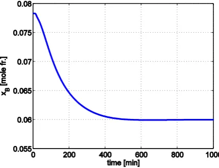
Figure 29. xD evolution to a step change of set-point xDi. The process response on channel c2 xB is proper for the use of standard internal model control method. The best tuning parameters obtained in this case were:
KC2 = 1, KM2 = 1.8, TM2 = 70 min. and Tm2 = 10 min., the system response for a step change from 0.078 mole fr. to 0.06 mole fr. of the set-point xBi
being presented in Fig. 30.
Fig. 31-32 present two examples of the concentrations time evolutions to changes of the two disturbances (F and xF).
Figure 31. xD evolution to a 3% decrease of xF.
Figure 32. xB evolution to a 3% decrease of F.
From Fig. 31-32 it can be observed that the two controllers work properly so that the errors produced by the two disturbances are eliminated.
Taking into account the results presented in this section it can be stated that the standard internal model control method is simple and robust, these results being confirmed also by [18, 19, 20].
B. Optimal control level for BBSC
The control system from this level is similar with the one used for the PPSC. For this column, the specification for the overhead product is fixed, xDi
= 0.96 mole fr., and refers to the concentration of the isobutene-isobutylene mixture in distillate. The quality specification for the bottom product is associated to the concentration of the same mixture in the bottom product, and is flexible, xBi [0.01…0.09] mole fr.
In this case, the objective function is
) (
) (
3
B L F r pr
x B p MM x
F
st
i B B
i B CL obj
with: prst – price of steam, [lei/kg]; p - price difference between isobutane – isobutylene mixture
and nbutane – (cis+trans)-butylene mixture, [lei/kg]; B
- bottom product flowrate, [kmole/min]; MMB - molar mass of nbutane – (cis+trans)-butylene mixture, [kg/kmole].
The objective function considers the optimum recovery of the isobutane – isobutylene mixture with as low as possible energy effort. The controller from this hierarchical level contains a control mathematical model of the process, the objective function, and an algorithm for determining the optimum. Fig. 33 shows a representation of the objective function.
Figure 33. Objective function representation.
The optimization problem solving led to the optimum value of xBi, namely xiB_opt = 0.072 mole fr.,
which is sent as set-point of the control system for the
xB concentration from the second hierarchical level, as it can be seen from the simulation scheme in Fig. 34.
Figure 34. Simulation scheme of the hierarchical control system with 3 levels for BBSC.
From Fig. 35 it can be observed that the xB control system brings the concentration to the optimum set-point value received from the third hierarchical level.
VI. CONCLUSIONS
The paper presents a hierarchized distributed control system of a gas processing unit consisting of three distillation columns. This system is hierarchized on vertical and distributed on horizontal within each level.
The hierarchical system for C3-C4 separation column has two levels: conventional control level (represented by LV control structure) and optimal control level. For this column is proposed an objective function which designates a (theoretical) profit obtained from the selling of the separated products in PPSC and BBSC, from which is deducted the costs associated with utilities (steam, in this case) from the CL1 column. The maximization of the objective function led to a good separation with xD = 0.9934 mole fr. and xB = 0.0057 mole fr., the profit being of tens of thousands of lei/h.
For the propane-propylene separation column the proposed hierarchical system has three levels: conventional control level (LB control structure), advanced control level and optimal control level. Because the disturbances associated with this column have an important influence on the concentrations, at the second hierarchical level is proposed a feedforward control system. The performed simulations in this case demonstrated that the disturbances effects on concentrations are compensated with success. At the optimal control level is implemented an objective function whose minimization led to xiB_opt = 0.0526 mole fr., which
ensure the recovery of the most valuable product with as low as possible energy effort. The output of this level is set as set-point for the control system from level 2.
The hierarchical system for the butane-butylene separation column presents at the first level the conventional control for this column (LB control structure), the second level consist in an advanced control system and the third level is dedicated to optimal control. Because the column presents crossed interactions between control loops, first a nonlinear decoupler is proposed to eliminate the effects of the mentioned interactions. The simulation results demonstrated the viability of this solution. Consequently, for the concentrations control can be used monovariabile controllers for each concentration. The proposed controllers use standard internal model algorithms. The IMC controllers proved their robustness also to disturbances changes, the errors being completely eliminated. The decoupler together with the IMC controllers are at the advanced control level. The objective function from the optimal control level is similar to the one from the propane-propylene separation column. In both cases, the controller from this level contains a mathematical model of the process, the objective function and an algorithm for determining the optimum.
REFERENCES
[1] G. Hewitt, J. Quarini, and M. Morrell, “More efficient distillation”, CHEM ENG L, (690), pp. 16-18, 1999. [2] M. Khalifa and M. Emtir, “Rigorous optimization of
heat-integrated and Petlyuk column distillation configurations based on feed conditions”, Clean Technologies and Environmental Policy, Vol. 11, No. 1, pp. 107-113, 2009. [3] L. Szabó, S. Németh, and F. Szeifert, “Three-level control of
a distillation column”, Engineering, Vol. 4, No. 10, pp. 675-681, 2012.
[4] G. Wilson, Distillation column dynamics and control, PhD Thesis, University of Canterbury, New Zeeland, 1979. [5] S. Mihalache and M. Popescu, “Modern method of generating
the best control structure for binary distillation columns”, Proceedings of the 11th WSEAS International Conference on SYSTEMS, Agios Nikolaos, Crete Island, Greece, pp. 75-80, 2007.
[6] S. Skogestad and M. Morari, “Understanding the Dynamic Behavior of Distillation Columns”, Ind. Eng. Chem. Res., 27, 10, pp. 1848-1862, 1988.
[7] S. Skogestad, “The dos and don’ts of distillation column control”, Chemical Engineering Research and Design, Vol. 85, Issue 1, pp. 13-23, 2007.
[8] S. Skogestad and I. Postlethwaite, Multivariable feedback control, 2nd Edition, John Wiley & Sons, 2007.
[9] M. Popescu, “Selection of control configurations for a gas separation unit”, Petroleum-Gas University of Ploiesti Bulletin, vol. LXVI, Technical Series, No. 2/2014, pp. 81-90, 2014.
[10] M. Popescu and S.F. Mihalache, “Hierarchical control of a depropanizer column”, Petroleum-Gas University of Ploiesti Bulletin, vol. LXVI, Technical Series, No. 4/2014, pp. 53-60, 2014.
[11] N. Paraschiv, M. Popescu, and C. Pătrăşcioiu, “Advanced real time control of an industrial mass transfer process”, Proceedings of the International Conference on Computational Heat and Mass Transfer (ICCHMT09), Guangzhou, China, pp. 602-607, 2009.
[12] M. Popescu, “Hierarchical control system design for a propylene-propane separation column”, Proceedings CSCS – 17, 17th International Conference on Control Systems and Computer Science, Bucharest, România, Vol. 2, pp. 105-108, 2009.
[13] M.R. Fenske, “Fractionation of straight-run Pennsylvania gasoline”, Ind. Eng. Chem., 24, pp. 482-485, 1932.
[14] E.R. Gilliland, “Multicomponent rectification: estimation of the number of theoretical plates as a function of the reflux ratio”, Ind. Eng. Chem., 32, pp. 1220-1223, 1940.
[15] A.J.V. Underwood, “Fractional distillation of multicomponent mixtures”, Chem. Eng. Prog., 44, pp. 603, 1948.
[16] H.E. Eduljee, “Equations replace Gilliland plot”, Hydrocarbon Proc., 54, pp. 120-122, 1975.
[17] V. Cîrtoaje, Frâncu S., and A. Băieşu, “A practical control procedure for multivariable systems”, In: SINTES 11 Proceedings: The XIth International Symposium on System Theory, Automation, Mechatronic Systems, Craiova, Romania, Vol. I, pp. 18-23, 2003.
[18] S. Frâncu and M. Popescu, “On the internal model control applied to propylene separation process”, Petroleum-Gas University of Ploiesti Bulletin, vol. LV, Technical Series, No. 2/2003, pp. 109-118, 2003.
[19] A. Băieşu, M. Popescu, and S. Frâncu, “Adaptive internal model control of a distillation column”, Proceedings of 7th International Carpathian Control Conference ICCC’2006, Czech Rep., pp. 145-148, 2006.