http://dx.doi.org/10.4236/ica.2015.64020
A Novel Technique for Detection of Time
Delay Switch Attack on Load Frequency
Control
Arman Sargolzaei1, Kang K. Yen1, Mohamed N. Abdelghani2, Abolfazl Mehbodniya3, Saman Sargolzaei4
1Department of Electrical and Computer Engineering, Florida International University, Miami, FL, USA 2Department of Mathematics and Statistics, University of Alberta, Edmonton, Canada
3Graduate School of Engineering-Sendai, Tohoku University, Sendai, Japan
4Department of Electrical and Computer Engineering, Wentworth Institute of Technology, Boston, MA, USA
Received 7 August 2015; accepted 27 October 2015; published 30 October 2015 Copyright © 2015 by authors and Scientific Research Publishing Inc.
This work is licensed under the Creative Commons Attribution International License (CC BY). http://creativecommons.org/licenses/by/4.0/
Abstract
In this paper, we focus on the estimation of time delays caused by adversaries in the sensing loop (SL). Based on the literature review, time delay switch (TDS) attacks could make any control sys-tem, in particular a power control syssys-tem, unstable. Therefore, future smart grids will have to use advanced methods to provide better situational awareness of power grid states keeping smart gr-ids reliable and safe from TDS attacks. Here, we introduce a simple method for preventing time delay switch attack on networked control systems. The method relies on an estimator that will es-timate and track time delays introduced by an adversary. Knowing the maximum tolerable time delay of the plant’s optimal controller for which the plant remains stable, a time-delay detector issues an alarm signal when the estimated time delay is larger than the minimum one and directs the system to alarm state. In an alarm state, the plant operates under the control of an emergency controller that is local to the plant and remains in this mode until the networked control system state is restored. This method is an inexpensive and simple way to guarantee that an industrial control system remains stable and secure.
Keywords
1. Introduction
Modern power grids rely on telecommunication technologies for control and monitoring, in a way to improve efficiency and reliability distribution. However, their reliance on computers and multi-purpose networks makes them vulnerable to cyber-attacks [1]-[3]. Recently, the investigation of attack methods on industrial control sys-tems and their countermeasures have been the focus of many academic, industries, and governments. Here, we will investigate one type of attacks on a power control system recently proposed by Sargolzaei et al. [4]-[6] that is time delay switch attack and we provide a simple detection/estimation technique for time delays caused by an adversary. State estimation is one of the pivotal features of future power systems [7]. According to [8], improv-ing the resiliency and reliability of smart distribution networks could be obtained via deployimprov-ing renewable re-sources and demand side management programs. As it has been mentioned in [9], demand response can ameli-orate the load curve by motivating smart customers utilizing smart communication infrastructure and smart me-ters.
The controller design for systems with time delay is one of the interests of many researchers [10]-[12] but they have not studied that time delay can be injected to the system as an attack. Time delays injected by a hacker in a control system would, in general, destabilize the system or cause inefficiency in performance of the system. This is a new attack in the context of power systems (e.g., load frequency control (LFC)) on networked control systems (NCS) [13] and is named time-delay-switch attack or TDS for short [4]. To avoid possible damage of TDS attacks, systems and controllers must be redesigned in a way to detect and correct for variable time delays. Time delays exist in power systems, in the sensing and control loops. The traditional controllers of power systems are designed based on current information being available and ignoring time delays even if they present. However, power grids technologies are continuously being improved by introducing new telecommunication technologies for monitoring to improve efficiency, reliability and sustainability of supply and distribution. For example, the introduction of a wide area measurement system (WAMS) provides synchronized near real-time measurements in phase measurement units (PMUs). WAMS which are used for stability analysis of power sys-tems can also be used for designing more robust controllers. Nevertheless, time delays are present in PMUs measurements as a result of natural transmission lines [14].
Several studies have considered the problem of stability of power systems with time delays [10] [11]. The impact of time delays on the power system controllers was discussed in [15]-[19]. In [20], authors studied the effects of delays on the small signal stability of power systems. In [15] and [16], methods to eliminate oscilla-tions that resulted from time-delayed feedback control were proposed. Authors in [21] presented a wide-area control system for damping generator oscillations. Using phasor measurements, but with delays, a controller was proposed in [14] and small signal stability of the power system was considered. A feedback controller designed for power systems with delayed states was proposed in [22]. This controller deals with the combined effects of the instantaneous as well as delayed states using the quadratic Lyapunov function for systems with delays. Ad-ditional studies on power systems with delay can be found in [2] [3] [10]-[12] [23]-[25] and the references therein. However, most of these studies considered either the construction of controllers that were robust to time delays or controllers that used offline estimate of time delays. As far as we know, there are no control methods that perform online estimation of dynamic time delays and real time control of power systems. Furthermore, few studies [26] [27] considered control of power systems with time delays introduced by adversary.
In this paper, we will describe a simple yet effective method to address a TDS attack on the observed states of a controlled system. Our method utilizes a time delay estimator, a communication protocol to alarm for time de-lay switch attack, a buffer to store the history of controller commands and an optimal controller to stabilize or track a reference signal and a local to the plant emergency controller to stabilize the plant if large time delays are detected. For now, we will only deal with LTI systems in state feedback.
2. Method
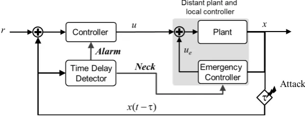
The proposed method is shown in Figure 1. Its basic elements are: plant model, time delay detector, emer-gency controller and controller. The controller can either be a PID controller or an optimal feedback controller. The emergency controller’s job is to stabilize the system in case of an attack on the communication lines of the distant controller. The time delay detector estimates the time delay in the communication channel from teleme-tered data. If the delay is larger than a maximum allowed time delay it sends alarm signals to the controller and emergency controller. If an alarm signal is received by the emergency controller it will begin to operate in a way to stabilize the plant to a desired state while the distant controller stops to operate until the delay is corrected.
Suppose the system we are dealing with is linear time invariant (LTI) or can be approximated in a region of interest by a LTI system,
( )
( )
( )
x t =Ax t +Bu t , (1) where x and u are state and control vectors, respectively. Matrices A and B are constant matrices with suitable dimensions.
Then, the solution is given by
( )
( )( )
0 0
e e d
t A t s At
x t = x +
∫
− Bu s s (2)with time delay τ, either a time-delay switch attack or a natural delay, the solution of Equation (2) becomes
(
)
( ) ( )( )
0 0
e e d
t
A t A t s
x t x Bu s s
τ
τ τ
τ − − − −
− = +
∫
. (3)Let us write the solution x t
( )
at the time t in terms of the solution with the time delay τ; we have( )
( )( )
( )( )
(
)
( ) ( )( )
0 0
0 0
e e e e d e d
e e e e d ,
t t
A t s A t s
At A A
t t
A t A t s
At A
t
x t x Bu s s Bu s s
x x t x Bu s s
τ
τ τ
τ
τ τ
τ
τ
−
− − −
−
− −
−
= + +
= + − − +
∫
∫
∫
(4)
In general, the time delay τ is an unknown variable. Let’s assume that τ is slowly varying, compared to the changes in u and x, and τˆ is our estimate of the time delay τ. Then, ε τ τ= −ˆ is the estimation error in the time delay. The predicted state x tˆ
( )
of the system based on the estimate of time delay τˆ is given by( )
ˆ(
)
( ˆ) ( )( )
0 0
ˆ
ˆ e e ˆ ˆ e e d
t
A t A t s
At A
t
x t x τ x t τ x Bu s s
τ
τ − −
−
= + − − +
∫
(5) [image:3.595.163.463.591.707.2]where x tˆ
(
−τˆ)
is the estimate of the delayed state given the estimate of the delay τˆ (i.e. a simulated signal). It should be noted that, x t(
−τ)
is what we actually measures and deliver to the plant model. So, at every in-stance of time, the variables x tˆ( )
, x tˆ(
−τˆ)
, u t( )
, A, B and x t(
−τ)
are known to the controller and the plant model. On the other hand, the current state x t( )
and the time delay τ are unknown. It’s essential that the plant model estimates state x t( )
accurately. Because of the delay, an accurate enough estimation of x t( )
requires a good estimate of the delay τ. We will show how to estimate the delay τ.The estimation error in states can be described by em
( ) ( ) ( )
t =x t −x tˆ and with delay it is given by(
; ,ˆ) (
) (
ˆ ˆ)
m
e t
τ τ
=x t− −τ
x t−τ
. (6) Then the idea is to estimate τˆ overtime as fast as possible to minimize the error em(
t; ,τ τ
ˆ)
. Using thegra-dient descent method, we set
ˆ d , ˆ d v t τ η τ ∂ = −
∂ (7)
where η is the learning parameter and select 1 2 2 m
v= e . With some manipulation, we have
(
) (
)
(
)
( ) ( )( )
( )( )
( )(
)
( )( )
( ) ˆ ˆ ˆ 0 0 ˆ ˆ ˆ 0 0 ˆ ˆ 0 ˆ ˆ ˆ d ˆ ˆ d ˆ ˆe e d
ˆ ˆ
e d e
ˆ
ˆ e 0 e
m
m m
t
A t A t s
m m
t
A t s A t
m m
A t A t
m
x t x t e
e e
t
x t
e e x Bu s s
e Bu s s e A x
e Bu t Bu A x
τ τ τ τ τ τ τ τ τ τ
τ η η
τ τ τ η η τ τ η η τ η τ − − − − − − − − − − ∂ − − − ∂ = − = − ∂ ∂ ∂ − ∂ = = + ∂ ∂ ∂ = − ∂ = − − − −
∫
∫
. (8)
Assuming that, u
( )
0 =0, which is reasonable for initial time, we arrive at(
)
( ˆ)0 ˆ
d
ˆ e , 0 ˆ
d
A t m
e Bu t A x t
t
τ
τ = −η −τ − − ≤ ≤τ
(9)
Equation (9) is the one we will use to estimate the time delay τ. However, there are practical issues that we need to consider. Computing machines have finite memory and temporal resolution. Therefore, we are unable to implement Equation (9) without discrete approximation and boundedness assumptions. To guarantee stability of calculations and limit our memory usage we have to add the following condition, τ τ< max. This condition will allow us to construct a finite buffer to store the history of u t
( )
from t to t−τmax.After designing the time delay estimator, we turn our attention to the controller and emergency controller. The controller can either be a PID controller or an optimal controller depending on the requirements of the applica-tion. Equation (10) is the PID controller and Equation (11) is the optimal controller,
( )
( )
( )
( )
0 d d , d tP D I
e
u t K e t K t K e s s t
= + +
∫
(10)( )
( )
.u t =Ke t (11) where the error is e t
( ) ( ) ( )
=r t −x t . Either controller, i.e., the PID or the optimal controller, can be designed in a way to be robust to some maximum time-delay τstable. The emergency controller sits close to the plant and operates only in case of emergency, for example, an attack on the communication line between the plant and controller. The emergency controller could either be a PID controller or optimal controller with the goal to sta-bilize the system to a particular reference trajectory rE.Suppose there is a time delay attack on the system with delay τ; the time delay estimator will estimate the delay τˆ. The cyber-attack detector will use the time delay estimate to perform the following function
stable ˆ 1
0 otherwise
c D= τ > τ
, (12) where c is a constant between 0 and 1. In case D = 1 an alarm signal is sent to the controller to shut it down and a negative acknowledgement is sent to the emergency controller to stabilize the plant. The control strategy is shown in Figure 1.
3. Result
We focus on the LFC system where the controller’s function is to regulate the states of a networked power plant. The multi interconnect LFC dynamic system description can be found in [4]. Here we focus on two-area power system with the attack model as
( )
( )
( )
( )
0 0l
X t AX t BU t D P
X X = + + ∆ =
. (13)
The optimal feedback controller is given by
( )
ˆ( )
U t = −KX t (14)
and the new state after the attack can be modeled by
( )
(
)
ˆ ,
X t =X t−τ (15) where τ =
[
td1,td2,,tdN]
T are different/random time-delays and are positive values. When td1,td2,,tdN areall zero, the system is in its normal operation. An adversary can get access to the communication link and inject a delay attack on the line to direct the system to abnormal operations.
In (13), X t
( )
= x t1( )
x t2( )
T denotes the states in the first and second power areas. Then the state vector in the thi power area is defined as
( )
( )
( )
( )
( )
( )
T1, 2,
i i i i i
i g tu pf
x t = ∆ f t ∆P t ∆P t ∆P t Λ t i= (16) where ∆fi
( )
t , ∆P tgi( )
,( )
i tu P t
∆ , ∆Ppfi
( )
t and( )
it
Λ are frequency deviation, power deviation of the ge- nerator, position value of the turbine, tie-line power flow, and control error on the ith power area, respectively [19]. The control error of the ith power area is expressed as
( )
( )
0 d , t i i it β f s s
Λ =
∫
∆ (17)where βi denotes the frequency bias factor.
In the dynamic model of the two-area LFC (13):
11 12 21 22 , A A A A A =
(18)
{
T}
T T 1 2
diag ,
B= B B (19)
{
T T T}
1 2
diag ,
D= D D (20)
and Aii, Aij, Bi and Di are represented by
1
1 1
0 0
1 1
0 0 0
1 1
0 0 0
2π 0 0 0 0
0 0 0 1
i
i i i
tu i tu i ii
i g i g i
N ij i j
j i
J J J
T
i g i
T B
= 0 0 1 0 0 (22)
0 0 0 0 0
0 0 0 0 0
0 0 0 0 0
2π 0 0 0 0
0 0 0 0 0
ij
ij
A
T
=
−
(23)
and
T 1
0 0 0 0
i i
D J
= −
(24)
where i and j can only be values one and two, Ji, ωi, µi, Tg i and Ttu i are the generator moment of inertia,
the speed-droop coefficient, generator damping coefficient, the governor time constant, the turbine time constant in the ith power area and Tij is the stiffness constant between the
th
i and the jth power areas, respectively. The analysis starts with the design of an optimal controller for the LFC in the normal operation (i.e., with no attack). Consider the system model described by (13) with the performance index described by
( )
( )
( )
( )
{
T T}
0 1
d , 2
f
t
J=
∫
X t QX t +U t RU t t (25)where matrix Q∈Rn n× is positive semi-definite and R∈Rm m× is positive definite. Then, the optimal control problem is to obtain optimal control U*
( )
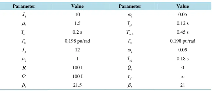
t that minimizes the performance index (25), subject to the dynamic of the system with no time-delay in its states.Simulation studies have been conducted to evaluate the effects of TDS attacks on the dynamics of the system and detect TDS attacks to direct the controller to emergency state. By solving the Riccati matrix equation we obtain the close loop control law in the form of state feedback. For the simulations we have used discrete li-near-quadratic regulator design from continuous cost function called “lqrd” function in MATLAB 2013a. Table 1 shows parameter values used in this process. We also set both ∆Pl1 and
2
l P
∆ to zero.
In our simulation, the total simulation time is 50 second and the sampling time is 0.01 s as its common in in-dustrial applications. To show accuracy of our proposed TDS attack detector/tracker, we didn’t send negative acknowledgment to the local controller for the first simulation to only track the injected time delay to the system. The simulation has been done for three different scenarios: 1) single TDS attack on one power area, 2) Simulta-neous TDS attack on both power areas, 3) Complex varied TDS attack on both power areas.
[image:6.595.144.484.576.722.2]1) Single TDS attack to one power area: Here, we considered that adversary attacks the third state of the first power area at time of 2 second for a delay value of 3 seconds and the time delay is increased to 4.5 seconds at time of 7 seconds. Figure 2 shows that the detector accurately tracked and monitored the TDS attack or any
Table 1.Parameter values for a two-area power system controller design.
Parameter Value Parameter Value
1
J 10 ω1 0.05
1
µ 1.5 Tg1 0.12 s
1
tu
T 0.2 s Ttu2 0.45 s
12
T 0.198 pu/rad T21 0.198 pu/rad
2
J 12 ω2 0.05
2
µ 1 Tg2 0.18 s
R 100 I Qf 0
Q 100 I tf ∞
1
natural delay on the system.
2) Simultaneous TDS attack to both power areas: In this scenario, we attack the third state of both power areas. TDS attacks 1 and 2 have been injected to the first and the second power areas respectfully. TDS attack 1 is started at time 2 seconds for value 3 seconds and increased at time 8 seconds to the value of 4.5 seconds. Also TDS attack 2 is started simultaneously with TDS attack 1 for the value of 1.5 seconds and increased to the value of 6 seconds. Figure 3 shows the result.
[image:7.595.167.492.350.712.2]3) Complex varied TDS attack to both power areas: In the last scenario we injected the TDS attack at dif-ferent time with difdif-ferent time-delay values. We assume that an adversary injects TDS attack to feedback lines of both power areas. In our simulation, an attacker starts TDS attack to the second power area (third state) at time 1 second for td3 =5 s and then increases it to td3=10 s at 20 second. Furthermore, adversary starts to attack the first power area (third state), at 1 second with td8=3 s and increased it to td8 =4.5 s at 30 second.
Figure 4 and Figure 5 show TDS attack tracking real time. Figure 4 shows TDS attack on the third state of the first power area and Figure 5 shows the attack on the same state of the second power area.
For the second part of our simulation we enabled the emergency controller to show the effect of our proposed technique for overcoming the TDS attack. We assume that an adversary injects TDS attack to the feedback lines of both power areas. In the simulation, a TDS attack was applied to the second power area (the third state) at time of 1 second for td3=5 s and then increases it to td3=10 s at 20 second. Furthermore, adversary starts to attack the first power area (the third state), at 1 second with td8=3 s and increased it to td8=4.5 s at 30 second. We also set the τstable=0.4 s based on stability analysis of LFC system in [4]. We send the negative acknowledgment to emergency controller in the case that detected value of time-delay is more than the maxi-mum allowed time-delay. Figure 6 and Figure 7 show the third state of the first and the second power areas
[image:7.595.185.443.351.517.2]Figure 2.TDS attack detection and tracking for third state of first power area.
Figure 3. TDS attack detection and tracking for simultaneous TDS attack on both power areas.
0 10 20 30 40 50
0 2 4 6 8 10
TDS Attack TDS Attack Tracker
0 10 20 30 40 50
0 2 4 6 8 10
[image:7.595.177.452.545.708.2]Figure 4. TDS attack detection and tracking for third state of first power area.
Figure 5. TDS attack detection and tracking for third state of second power area.
Figure 6. Value position of the turbine system under TDS attack for the first power-area control system.
0 10 20 30 40 50
0 2 4 6 8 10
Time (s)
T
im
e
D
el
ay
,
t d3
(t
)
T DS attack
T DS attack tracking
0 10 20 30 40 50
0 5 10 15 20
Time (s)
T
im
e
D
el
a
y
t d8
(t
)
T DS attack T DS attack tracking
0 10 20 30 40 50
-2 -1.5 -1 -0.5 0 0.5 1
Time(s)
x3
(t
)
[image:8.595.191.437.518.700.2]Figure 7. Value position of the turbine system under TDS attack for the second power-area control system.
under attack with traditional optimal controller (TOC) and the proposed control technique (PCT) respectively. As it’s clear on the result, the simulated attack makes the system unstable. With the proposed technique, we could overcome TDS attack on the simulated system.
4. Conclusion
In summary, we have demonstrated a simple method for estimating and detecting time delay switch attack on a networked control system. The method relies on a time delay estimator that estimates and tracks time-delays in-troduced by an adversary. With knowledge of the maximum time delay of the control system, for which the plant remains stable and secure, the time-delay detector compares the estimated time delay to the maximum al-lowed time delay and issues an alarm signal when the estimated time delay is larger than this value. It also di-rects the system to an alarm state. In an alarm state, the plant is under the control of the emergency controller, which is local to the plant. The plant remains in this mode until the networked control system state is restored and time-delay switch is eliminated. We think that this method is simple and an inexpensive way to assure that an industrial control system remains stable and secure.
Acknowledgements
The authors would like to thank the Resilient, Autonomous Networked Control Systems (RANCS) group for support during publishing this paper.
References
[1] Ericsson, G.N. (2010) Cyber Security and Power System Communication—Essential Parts of a Smart Grid Infrastruc-ture. IEEE Transactions on Power Delivery, 25, 1501-1507. http://dx.doi.org/10.1109/TPWRD.2010.2046654
[2] Zhang, C.-K., Jiang, L., Wu, Q.H., He, Y. and Wu, M. (2013) Delay-Dependent Robust Load Frequency Control for Time Delay Power Systems. IEEE Transactions on Power Systems, 28, 2192-2201.
[3] Yuan Y.L., Li Z.Y. and Ren, K. (2011) Modeling Load Redistribution Attacks in Power Systems. IEEE Transactions on Smart Grid, 2, 382-390.
[4] Sargolzaei, A., Yen, K. and Abdelghani, M.N. (2014) Time-Delay Switch Attack on Load Frequency Control in Smart Grid. Journal of Advanced Communication Technologies, 5, 55-64.
[5] Sargolzaei, A., Yen, K. and Abdelghani, M.N. (2014) Delayed Inputs Attack on Load Frequency Control in Smart Grid.
Innovative Smart Grid Technologies Conference (ISGT), 2014 IEEE PES, Washington DC, 19-22 February 2014, 1-5. http://dx.doi.org/10.1109/isgt.2014.6816508
[6] Sargolzaei, A., Yen, K.K. and Abdelghani, M.N. (2014) Control of Nonlinear Heartbeat Models under Time-Delay-
0 10 20 30 40 50
-6 -4 -2 0 2 4 6 8
Time(s)
x 8
(t
)
Switched Feedback Using Emotional Learning Control. International Journal on Recent Trends in Engineering & Technology, 10, 2.
[7] Amini, M.H., Sarwat, A.I., Iyengar, S.S. and Guvenc, I. (2014) Determination of the Minimum-Variance Unbiased Es-timator for DC Power-Flow Estimation. 40th IEEE Industrial Electronics Conference (IECON 2014), Dallas, 29 Octo-ber-1 November 2014, 114-118. http://dx.doi.org/10.1109/IECON.2014.7048486
[8] Amini, M.H., Nabi, B. and Haghifam, M.-R. (2013) Load Management Using Multi-Agent Systems in Smart Distribu-tion Network. IEEE PES General Meeting 2013, Vancouver, 21-25 July 2013, 1-5.
http://dx.doi.org/10.1109/pesmg.2013.6672180
[9] Kamyab, F., Amini, M. H., Sheykhha, S., Hasanpour, M. and Jalali, M.M. (2015) Demand Response Program in Smart Grid Using Supply Function Bidding Mechanism. IEEE Transactions on Smart Grid, 25 May 2015, 1949-3053. http://dx.doi.org/10.1109/TSG.2015.2430364
[10] Li, Y., Tong, S.C. and Li, Y.M. (2012) Observer-Based Adaptive Fuzzy Backstepping Control for Strict-Feedback Stochastic Nonlinear Systems with Time Delays. International Journal of Innovative Computing, Information and Control, 8, 8103-8114.
[11] Benzaouia, A., Ouladsine, M., Naamane, A. and Ananou, B. (2012) Fault Detection for Uncertain Delayed Switching Discrete-Time Systems. International Journal of Innovative Computing, Information and Control, 8, 8049-8062. [12] Sargolzaei, A.,Yen, K., Noei, S. and Ramezanpour, H. (2013) Assessment of He’s Homotopy Perturbation Method for
Optimal Control of Linear Time-Delay Systems. Applied Mathematical Sciences, 7, 349-361.
[13] Benéıtez-Péerez, H., Benéıtez-Péerez, A. and Ortega-Arjona, J. (2012) Networked Control Systems Design Consider-ing SchedulConsider-ing Restrictions and Local Faults. International Journal of Innovative Computing, Information and Control, 8, 8515-8526.
[14] Dotta, D., Silva, A.S. and Decker, I.C. (2009) Wide-Area Measurements-Based Two-Level Control Design Consider-ing Signal Transmission Delay. IEEE Transactions on Power Systems, 24, 208-216.
http://dx.doi.org/10.1109/TPWRS.2008.2004733
[15] Kamwa, I., Grondin, R. and Hebert, Y. (2001) Wide-Area Measurement Based Stabilizing Control of Large Power Systems—A Decentralized/Hierarchical Approach. IEEE Transactions on Power Systems, 16, 136-153.
http://dx.doi.org/10.1109/59.910791
[16] Wu, H.X., Tsakalis, K.S. and Heydt, G.T. (2004) Evaluation of Time Delay Effects to Wide-Area Power System Stabi-lizer Design. IEEE Transactions on Power Systems, 19, 1935-1941. http://dx.doi.org/10.1109/TPWRS.2004.836272 [17] Jiang, Q., Zou, Z. and Cao, Y. (2005) Wide-Area TCSC Controller Design in Consideration of Feedback Signals’ Time
Delays. IEEE Power Engineering Society General Meeting, 2, 1676-1680.
[18] Saad, M.S., Hassouneh, M.A., Abed, E.H. and Edris, A.A. (2005) Delaying Instability and Voltage Collapse in Power Systems Using SVCs with Washout filter-Aided Feedback. American Control Conference, 6, 4357-4362.
http://dx.doi.org/10.1109/acc.2005.1470665
[19] Chaudhuri, B., Majumder, R. and Pal, B. (2005) Wide-Area Measurement Based Stabilizing Control of Power System Considering Signal Transmission Delay. IEEE Power Engineering Society General Meeting, 2, 1447-1450.
http://dx.doi.org/10.1109/pes.2005.1489106
[20] Milano, F. and Anghel, M. (2012) Impact of Time Delays on Power System Stability. IEEE Transactions on Circuits and Systems I: Regular Papers, 59, 889-900. http://dx.doi.org/10.1109/TCSI.2011.2169744
[21] Ray, S. and Venayagamoorthy, G.K. (2008) Real-Time Implementation of a Measurement-Based Adaptive Wide-Area Control System Considering Communication Delays. IET Generation, Transmission & Distribution, 2, 62-70. http://dx.doi.org/10.1049/iet-gtd:20070027
[22] Alrifai, M.T.,Zribi, M., Rayan, M. and Mahmoud, M.S. (2013) On the Control of Time Delay Power Systems. Inter-national Journal of Innovative Computing, Information and Control, 9, 769-792.
[23] Yang, Q.Y., An, D. and Yu, W. (2013) On Time Desynchronization Attack against IEEE 1588 Protocol in Power Grid Systems. 2013 IEEE Energytech, Cleveland,21-23 May 2013, 1-5.
[24] Schenato, L. (2008) Optimal Estimation in Networked Control Systems Subject to Random Delay and Packet Drop.
IEEE Transactions on Automatic Control, 53, 1311-1317. http://dx.doi.org/10.1109/TAC.2008.921012 [25] Mahmoud, M.S. (2000) Robust Control and Filtering for Time-Delay Systems. Marcel Dekker Inc., New York. [26] Tan, Y.H. (2004) Time-Varying Time-Delay Estimation for Nonlinear Systems Using Neural Networks. International
Journal of Applied Mathematics and Computer Science, 14, 63-68.