Implementation for Two-Stage Hybrid Decoding for Low
Density Parity Check (LDPC) Codes
Hend A. Orabi
Thebes higher institute of Engineering Cairo, Egypt
A. Zekry
Ain Shams University Cairo, Egypt
G. Gomah
National Institute for Standards Giza, Egypt
ABSTRACT
LDPC codes are gaining high attention in Channel Coding field these days. However, one of the main problems facing usage of these codes in communication systems is the high complexity decoding scheme that results in high decoding delay. Such delay is not acceptable in some applications that depend on time such as video transmission. This paper presents hardware implementation technique for Two-Stage Hybrid decoder resulting in better complexity and delay. Also, it shows comparison between soft, hard and hybrid decoding techniques in terms of memory usage, and delay time as to be used for real implementation for some applications such as DVB-S2.
Keywords
Channel Coding, LDPC, VHDL, Hybrid decoding.
1.
INTRODUCTION
The first Low-Density Parity Check Code (LDPC) was discovered by Gallager [1], [2] in 1960s where this code proved the extraordinary performance with iterative decoding that was very close to Shannon limit which is difficult to reach. LDPC codes are used in many applications such as DVB-S2 [3], which is a standard for Digital Video Broadcasting–Satellite-Second Generation because of its excellent Bit Error Rate (BER) performance. These codes are expected to be included in many future standards as well as to replace many existing channel coding techniques.
There are many types of LDPC decoding algorithms that have good performance with acceptable delay time. These algorithms can be classified into soft-decision decoding algorithm such as the Sum-Product Algorithm (SPA) and hard-decision decoding algorithm such as Bit-Flipping (BF) algorithm which was discovered by Gallager. The Bit-Flipping algorithm has many modified versions [4], [5], [6] that have better BER performance compared to the original Bit-Flipping algorithm.
The good BER performance of SPA comes on the expense of the high complexity which increases the delay time for the used design. Such high delay is considered as a drawback for some applications especially for those who are greatly affected by the delay such as video and audio transmission. On the other side, hard decision such as Bit Flipping algorithm and its modified versions have limited BER performance with lower complexity and delay time if compared to (SPA).
So, Two-Stage Hybrid decoding algorithm proposed in [7] was used as a new decoding algorithm, where this algorithm provides a trade-off algorithm between hard and soft-decision algorithms and has better performance compared to that of BF
and less complexity and delay time compared to that of SPA. This paper shows an FPGA design of the real hardware implementation for Two-Stage Hybrid decoder with comparison to SPA, and BF in terms of memory usage and delay time.
The rest of the paper is organized as follows. Section (2) presents the background on SPA and BF algorithms. These algorithms provide the basis for the Two-Stage Hybrid decoding. Also, this section presents the existing Two-Stage Hybrid algorithm and how it is composed of SPA as the first stage and BF as the second stage. Section (3) introduces the hardware implementation technique for the three algorithms with showing the procedure of each algorithm to compare between their performances. Section (4) includes typical simulation results for the three decoders. Also, comparison between the three decoders is shown with respect to memory usage and delay time. Finally, conclusion and future work are presented in Section (5).
2.
THEROTICAL BACKGROUND
2.1
Sum-Product Algorithm
Sum-Product Algorithm (SPA) is the best performing decoding method (either soft-decision or hard-decision). It has been developed by Mackay and Neal as in [8]. It is an iterative decoding algorithm based on belief propagation which is more efficient for decoding (LDPC) codes.
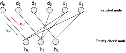
Starting with the encoder, the parity check matrix (H-matrix) is designed as shown in Figure 1 for systematic H-matrix. Tanner graph [9] is used to visualize the H-matrix with two pair of nodes as shown in Figure 2, the first one is the symbol node (parent node) which identify the number of column's elements (j) in H (dj) and the other node is the parity check
node (child node) which identify the number of row's element (i) in H (hi). As per the ones in the H-matrix, the connection
between two nodes is shown by the position filled by ones in each row and column in H matrix in the tanner graph (i.e. the entry {i,j} equals one (Hij=1)), elsewhere the connection is not
present. Qij x
represents the estimated probability of symbol node and Rijx represents the estimated probability of parity
check node.
SPA is a symbol-by-symbol soft-in/soft-out decoding algorithm that is based on the estimation of probabilities for each of parent and child nodes at the two states x (0, 1).First, symbol node dj estimates its probabilities Qijx from a priori
values of the soft decision of the received symbol in each state. Then, it sends these probabilities to the parity check node hi. After that, the parity check node checks to calculate
another set of probabilities Rijx in each state and sends it again
to the symbol node which computes a posteriori probabilities to take its hard decision for the decoded bit if it is ‘1’ or ‘0’.This decoding iteration continues until the number of iteration in the design is achieved or the syndrome condition is satisfied (equal to zero) based on:
S = r.HT (1)
where r is the hard decision decoded vector and HT is the transpose of parity check matrix for LDPC code.
d1
d6 d5 d4 d3 d2
h1
h2
h3
Q36x
R36x
Symbol node
[image:2.595.60.271.265.355.2]Parity check node
Fig 2: Tanner graph corresponding to the above H- matrix
2.2
Bit Flipping Algorithm
The Bit-Flipping (BF) algorithm is one of the hard-decision algorithms used for decoding LDPC codes. BF algorithm has many versions starting from the original BF algorithm designed by Gallager, then, weighted and modified weighted BF algorithms till the Reliability Ratio based Weighted Bit-Flipping (RRWBF) algorithm which is considered as the best performing BF algorithm [1], [2], [4], [5] and [6].
As for the Bit-Flipping algorithm procedure, the decoder first computes all parity-check sums (syndrome condition) to decide if the hard decision of the received vector is true or not. If the syndrome bits are not zero, then, the decoder will calculate the unsatisfied parity-check equation. From this equation, the bits of received vector can be changed (flipped).Using these new value of the received vector, the parity-check sums are recomputed and the process is repeated until all parity-check sums are satisfied or the number of iteration in the design is achieved.
The next modified versions of (BF) are the weighted [4] and modified weighted Bit-Flipping [5] where the weighted BF algorithm is improved to achieve better performance by calculating a new vector (weighted check sum) where each bit in this vector has a weight, where the only flipping bit in the received vector will be determined based on this weight. This algorithm has a disadvantage which is that, only one bit will be flipped in each iteration.
As for the modified weighted BF, it has improved performance than the weighted BF algorithm by designing a factor (α) which can be optimized for each SNR and hence improves the BER performance. The disadvantage of this algorithm is the optimization of the factor (α).
The last modified (BF) version is the Reliability Ratio based Weighted Bit-Flipping (RRWBF) algorithm [6] which defines
a new term called Reliability ratio (R). This term gives more reliability to take the right hard decision.
2.3
Two-Stage Hybrid decoding Algorithm
This algorithm was first proposed in [7] as a new decoding algorithm which mixes between soft-decision (presented in SPA) and hard-decision (presented in the BF algorithm) schemes. The aim of this algorithm is to have better performance than BF and less decoding complexity than that of SPA.At the first stage, the code is decoded using (SPA) with a small fixed number of iterations. At the completion of these iterations, hard decision of decoded vector is obtained. Then, this sequence of bits is decoded by the (BF) algorithm, as the second stage, for the remaining number of assigned iterations till the designed maximum number of iterations are achieved or the received codeword is decoded correctly (syndrome condition is satisfied).
3.
IMPLEMENTATION OF DECODING
ALGORITHMS
3.1
Sum-Product Algorithm
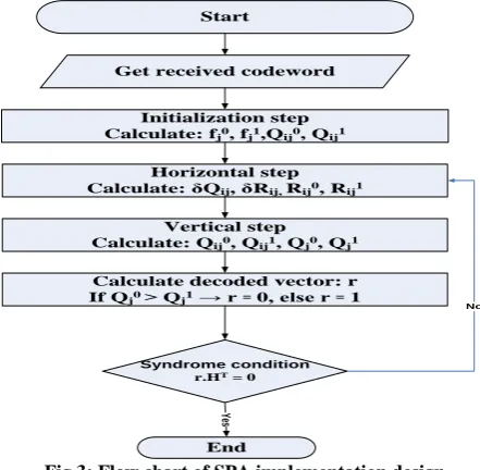
In this sub-section, the implementation of (SPA) is presented as shown in the flow chart in Figure 3. As for the VHDL implementation design, once the channel output is received at the decoder side, the design works on getting the maximum and minimum values of all possible received vectors. All values between maximum and minimum values are divided into (2k) intervals where k is the number of input bits/symbol. For each interval, fjx are calculated as:
(2)
Where fjx presents the probability x of '0' and '1' based on
Gaussian distribution in each state j, r is the received vector and σ is the standard deviation.
Fractional numbers are not used here for simplicity. So, all received values in each interval will be multiplied by 1000. The calculated probability values (fj0 and fj1) are mapped to
the corresponding interval such that the summation of fj0 and
fj 1
is equal to 2k-1 instead of 1.
After that, SPA has three steps to complete the decoding algorithm. These steps are the Initialization step, the Horizontal step and the Vertical step.
3.1.1
Initialization step
By determining initial values of Qijx (symbol node probability)
which are the same priori estimates of the probability (fjx) at a
given state (i,j) in H-matrix. These values are sent to parity check node to start horizontal step.
3.1.2
Horizontal step
After the initialization step, exchanging information between symbol and parity check nodes begins. The parity check node receives (Qijx) from its symbol node, then it calculates the
coefficient (δQij) where:
Q
ij=Q
ij0-Q
ij1(3)
From that, another two coefficients (δRij) and (Rijx) are
calculated as:
R
ij x= 0.5(1± δR
ij) (5)
All these coefficients are calculated in this horizontal step to increase the reliability of the probability of each bit to make the right bit decision in the vertical step.
3.1.3
Vertical step
This is the final step which is devoted to estimate the decoded vector at the current iteration x by calculating the posteriori probabilities Qjx. If Qj0 > Qj1 then the decoded bit is '0',
otherwise it is '1'.
The syndrome equation (1) is checked to see if the syndrome vector is zero or not. If it is not zero, updated Qij
x
are calculated to be used in the next iteration which starts from the horizontal step.
3.2
Bit Flipping Algorithm
In this sub-section, the implementation of (BF) is described according to the flow chart depicted in Figure 4. First, the parity-check sums are computed based on equation (1) where r is the hard decision of received codeword from the channel. It is designed to be six bits in the implemented design. S is the syndrome vector. The parity check matrix (H) for the LDPC is designed to be (6, 3) for the sake of simulation results, as in Figure 1. If all parity-check sums are satisfied which means that the syndrome bits are equal to zeros, then the decoding process is stopped and the output codeword will be the same as the received codeword.
Start
Get received codeword Initialization step Calculate: fj0, fj1,Qij0, Qij1
Syndrome condition r.HT = 0
End Horizontal step Calculate: δQij, δRij, Rij0, Rij1
Calculate decoded vector: r If Qj0 ˃ Qj1 → r ꞊ 0, else r ꞊ 1
Vertical step
Calculate: Qij0, Qij1, Qj0, Qj1
Ye
s
[image:3.595.325.537.71.274.2]No
Fig 3: Flow chart of SPA implementation design
If the syndrome bits are not zeros, an unsatisfied parity check equation is calculated based on:
y = S.H
(6)
where the output y will be used to identify the positions of the flipped bits in the received vector. For each bit in y, if the bit is larger than or equals to the previous bit, then the corresponding bit in the received codeword is flipped to obtain the decoded codeword.
These steps are repeated until all parity-check sums are satisfied or the maximum number of iterations in the design is reached.
Start
Get received codeword
Calculate decoded vector: r
Syndrome condition
r.HT = 0
End Syndrome condition
r.HT = 0
Calculate unsatisfied parity check equation: y
No
Ye
s
Yes
No
Fig 4: Flow chart of BF implementation design
3.3
Two-Stage Hybrid decoding Algorithm
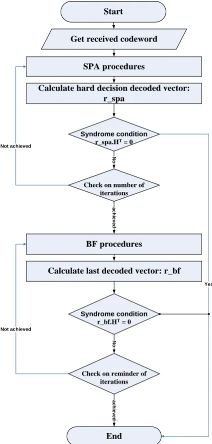
As for the implementation steps here, as shown in the flow chart of Figure 5, the first stage is the (SPA) algorithm with small number of iterations followed by the (BF) algorithm as the final and second stage for the remaining number of iterations. SPA with good performance first corrects most of the errors in the received codeword. Then, the output codeword from (SPA) will enter to the (BF) algorithm to correct the remaining errors with relatively small delay. The design of SPA and BF used here is the same as mentioned in the previous sections. [image:3.595.54.275.371.587.2]Start
Get received codeword
SPA procedures
Calculate hard decision decoded vector: r_spa
BF procedures
Calculate last decoded vector: r_bf
Syndrome condition
r_bf.HT = 0
End
Syndrome condition
r_spa.HT = 0
Yes Not achieved N o a c h ie v e d N o a c h ie v e d Not achieved
Check on number of iterations
[image:4.595.57.270.72.517.2]Check on reminder of iterations
Fig 5: Flow chart of Two-stage Hybrid implementation design
4.
SIMULATION RESULTS
The three decoders are implemented in MATLAB and in VHDL. The source codes are available upon request. As for simulation results for the three algorithms, the simulation results are divided into two parts:
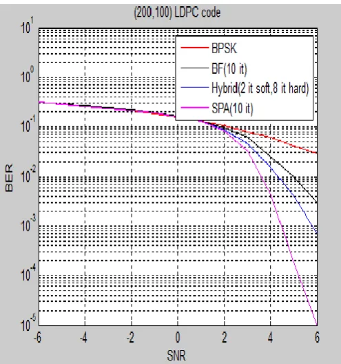
MATLAB Simulation for (200,100, 5) irregular LDPC code with 10 iterations assigned for each algorithm (BF, SPA and Two-Stage Hybrid) are presented. The iterations defined for Two-Stage Hybrid codec is divided into 2 iterations for SPA and 8 iterations for BF algorithm.
VHDL Simulation for (6, 3) irregular LDPC code is displayed as a case study using Xilinx software. For the case of hybrid algorithm, the iterations are divided into one iteration for (SPA) and two iterations for (BF) algorithm. The decoded vector is checked after each iteration in each algorithm to see if the syndrome is zero or not and compare its
4.1
MATLAB Simulation
MATLAB simulation results are shown in Figure 6 where the performance of the three decoders is measured by the bit error rate (BER) versus the ratio energy per bit divided by the noise density ratio (Eb/No) for additive white Gaussian noise channel (AWGN). As expected and in agreement with the previous work, the best decoder is the SPA and the worst is the BF one while the hybrid decoder has an intermediate performance. The MALAB simulation was necessary for the system level study and for driving test signals for the FPGA implantation to verify our design.
4.2
VHDL Simulation
Comparison between the three algorithms is based on Delay and Total Memory usage for each of the three algorithms where Delay is the time needed for logic gates and routes, and Total Memory usage is the memory used from the FPGA memory, shown in Table 1.
4.2.1
Sum-Product Algorithm
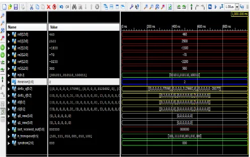
As for SPA simulation result shown in Figure 7, the received codeword from the channel, after multiplying by 1000, is designed to be six bits in the implemented design (from re0 to re5). By using the designed H-matrix, the probability of Gaussian distribution (f0 and f1) can be calculated in each state (j) which is the same values of the probability (q0 and q1) in the initialization step. The first iteration begins with the horizontal step to calculate of the probabilities (delta_q, delta_r, r0, r1) that is based on equation (3), (4) and (5) respectively. Then, the vertical step starts which calculate the posteriori probabilities (q0_new, q1_new) and the hard decision decoded vector (last_received_out) can be estimated. The syndrome condition (syndrome) that is calculated from equation (1) is not achieved here. So, the updated probabilities (q0_update, q1_update) are then calculated for using them in the next iteration.
The second iteration, shown in Figure 8, starts from the horizontal step. New values of (delta_q, delta_r, r0, r1) are calculated. After calculation of (q0_new, q1_new), the value of (last_received_out) is "000000" which is the corrected code, where the syndrome vector becomes zero. Then, the code is stopped and no need for the third iteration.
It is clear that the SPA has the best performance as the codeword is decoded correctly after two iterations only. This performance superiority comes on the expense on the complexity and delay values as will be shown later in Table 1.
4.2.2
Bit-Flipping Algorithm
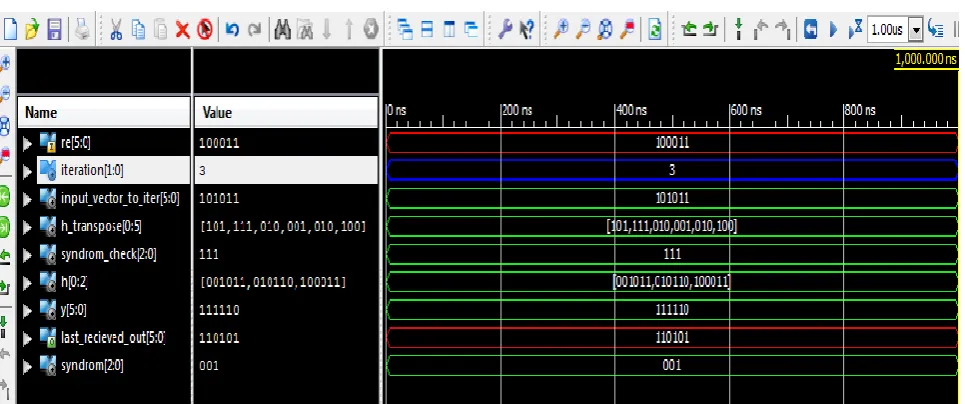
Then, the decoder enters the second and third iterations. Figure 10 and 11 show that the error still exists and the syndrome is not zero yet. The decoder stops after the third iteration as the maximum number of iterations is achieved. After finishing the last iteration, it is found that the decoded codeword has 4 error bits ‘110101’ if it is compared with the output of the SPA which is ‘000000’ as shown in Figure 8. So, it is clear that (BF) algorithm has less performance than (SPA).
4.2.3
Two-Stage Hybrid Algorithm
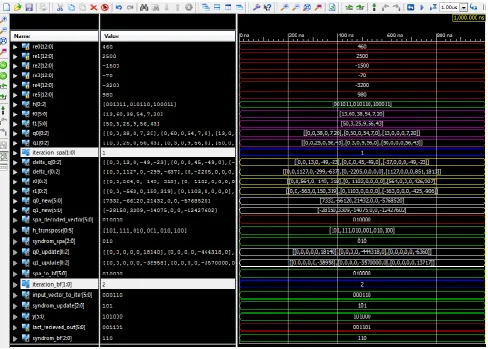
The Two-Stage Hybrid simulation result is shown in Figure 12. The first iteration is done with SPA step to obtain the output codeword (spa_decoded_vector) and its syndrome vector (syndrome_spa) which is non-zero bits.
The output of SPA enters to the BF step (spa_to_bf) for making the first iteration, to get an output vector where the syndrome vector is not zero.
For the second iteration of BF, the output vector from the first iteration enters to the second iteration (input_vector_to_iter) to obtain y that makes the decoded vector (last_received_out) to be "001101" which is not decoded correctly as the syndrome (syndrome_bf) bits are not zero.
Although the syndrome vector is not zero after the completion of the third iteration, the decoded vector has 3 error bits ‘001101’ when compared to that of SPA which is ‘000000’ as shown in Figure 8. But it is better than that of the BF algorithm ‘110101’ as shown in Figure 11.
[image:5.595.313.561.73.337.2]As for the comparison between the decoding algorithms, Table 1 shows the values for the three algorithms.
Table 1. Comparison between the three algorithms after three iterations
Fig 6: MATLAB Simulation result for the three algorithms
Resources SPA Two-Stage
Hybrid
BF
Device FPGA, Xilinx, Vertex 6 XC6VLX75T LDPC
code
1/2 rate (6,3) irregular code
LUTs 5371 (11%) 1825 (3%) 5 (0%)
Registers 5371 1825 5
IO Buffers 84 (35%) 84 (35%) 12(5%)
DSPs 226 (78%) 60 (20%) 0
Delay 78.339ns (59.808ns logic, 18.531ns
route)
26.250ns (19.947ns logic, 6.303ns
route)
0.954ns (0.059ns logic, 0.895ns
route) Memory
usage
[image:5.595.48.294.458.624.2]Fig 7: VHDL Simulation result for the SPA first iteration
[image:6.595.55.553.424.735.2]Fig 9: VHDL Simulation result for the BF first iteration
Fig 10: VHDL Simulation result for the BF second iteration
[image:7.595.59.542.534.736.2]Fig 12: VHDL Simulation result for the Two-stage Hybrid
5.
CONCLUSION AND FUTURE WORK
In this paper, performance comparison between SPA, BF and Two-Stage Hybrid decoding is shown, which proves the same results achieved before through simulations in previous research papers. The novelty in this paper is the implementation comparison between the three algorithms in terms of the delay and memory usage which approves the same concept through hardware simulation and especially for Two-Stage hybrid scheme which shows good performance with less complexity.
As for future work, it is recommended to change number of iterations assigned for both parts (hard and soft) of hybrid scheme to get the best results that can be used for different systems based on systems’ requirements. Also, we can use FPGA kits to test this hardware implementation that can be used in some systems like DVB-S2.
6.
REFERENCES
[1] R. G. Gallager, “Low density parity check codes,” IRE Trans. Inform. Theory, vol. IT-8, pp. 21–28, Jan. 1962. [2] R. G. Gallager,”Low Density Parity Check Codes",
Cambridge, MA: MIT Press, 1963.
[3] Digital Video Broadcasting (DVB); Second generation framing structure, channel coding and modulation systems for Broadcasting, Interactive Services, News Gathering and other broadband satellite applications (DVB-S2), ETSI EN 302 307, V1.2.1, April 2009.
[4] Y. Kou, S. Lin, and M. Fossorier, “Low density parity check codes based on finite geometries: A rediscovery and more,” IEEE Trans. Inform. Theory, vol. 47, pp. 2711–2736, Nov. 2001.
[5] Zhang, J., and Fossorier, M.P.C.: ‘A modified weighted bit-flipping decoding of low-density parity-check codes’, IEEE Commun. Lett., 2004, 8, (3), pp. 165–167
[6] Guo, F., and Hanzo, L.: ‘Reliability ratio based weighted bit-flipping decoding for low-density parity-check codes’, Electron. Lett., 2004, 40, (21), pp. 1356–1358 [7] H. R. Zeidan, Maha M. Elsabrouty, “Two-Stage Hybrid
decoding for low-Density parity Check codes,” in 4th International Conference on Innovations in Information Technology, 2007, IT'07, Dubai, UAE, Nov 2007, pp. 650–654.