Performance Improvement of BER in OFDM System
using Feed Forward Technique on Power Amplifier
Ehab AbdulRazzaq Hussein
Electrical Department /College of Engineering Babylon University
Babylon, Hillah (Iraq)
Mohammed A. Abdulkadhim
Electrical Department /College of Engineering Babylon University
Najaf, Kufa (Iraq)
ABSTRACT
Orthogonal Frequency Division Multiplexing (OFDM) transmission is an effective way to deal with multipath, being its implementation less complex than traditional equalizers. OFDM is characterized by the efficient of implementation because using fast Fourier transform (FFT) algorithm which made it ideal for new technology. It also features that it sensitive to nonlinear distortions due to its high peak to average power ratio values. OFDM system performance is affected by nonlinear characteristics of the high power nonlinear amplifier, where nonlinear amplification of OFDM signal caused by the Nonlinearities of the power amplifier. In this paper, the effect of feedforward linearization technique on high power amplifier nonlinearity for the OFDM system is studied. The feedforward linearization technique is a renowned linearization method to reduce out-of-band distortion of power amplifier. Computer simulations of the OFDM system show the OFDM signal measurements such as OFDM spectrum with and without linearization technique. Bit error rate (BER) also has been calculated and then compared to different modulation techniques with and without the presence of the of feedforward linearization technique.
Keywords
OFDM (Orthogonal Frequency Division Multiplexing), HPA (High Power Amplifier), FFLT (Feed-Forward Linearization Technique), LT (Linearization Technique), ACPR (Adjacent Channel Power Ratio), IP (Input Power).
1.
INTRODUCTION
OFDM (Orthogonal Frequency Division Multiplexing) is a multi-carrier transmission technique that is an excellent method for high speed bi-directional wireless data communication [1]. OFDM is very similar to the well-known and used technique of Frequency Division Multiplexing (FDM). OFDM uses the principles of FDM to allow multiple messages to be sent over a single radio channel. It is however in a much more controlled manner, allowing an improved spectral efficiency [2]. An OFDM signal consists of a sum of subcarriers that are modulated by using phase shift keying (PSK) or quadrature amplitude modulation (QAM). Although OFDM provide good spectral efficiency, they produce a signal with a fluctuating envelope that generates intermodulation distortion (IMD) at the system’s power amplifiers. Most of the IM power appears as interference between adjacent channels, which requires the use of highly linear power amplifiers. Considered Back-off power is the
simplest way to improve the linearity of the power amplifier which corresponds to moving the operating point of the amplifier to the linear region. Increasing the back-off of the power amplifier means that the signal is contained better in the linear range, and thus the effects of nonlinearities are reduced. However, power efficiency is reduced as well. So a tradeoff between efficiency and linearity must be made. Linearization techniques prove to be the best solution in order to improve power amplifiers linearity without having negative impact on efficiency [3]. There are several kinds of linearization techniques for power amplifiers have been proposed such as Feedforward, Feedback, Predistortion, Linear amplification using Nonlinear Component [LINC] and Envelope Elimination and Restoration [EER]. In this paper, the main objective is to study the impact of amplifier nonlinearity for different modulations techniques and the effect of feed foreword correction techniques on it in OFDM system. Feed-forward linearization is the only strategy that simultaneously offers wide bandwidth and good IMD suppression. The price for this performance is high complexity. In addition, automatic adaptation mechanisms are essential for maintaining performance regardless of variables such as temperature and component drift [4].
2.
BASIC PRINCIPLE OF OFDM
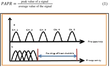
36 The advantages of using OFDM are many, such as high
spectrum efficiency as Figure 1, robustness to channel fading, less sensitive to sample timing offsets than single carrier systems, immunity to impulse interference, and ease of filtering out noise. The main disadvantages of OFDM system are that its RF signal suffers from high peak to average power ratio (PAPR) due to the transmission of many sub-carriers and More sensitive to ICI (inter carrier interference) which is due to frequency offset. The PAPR of a signal is given as:
𝑃𝐴𝑃𝑅 = peak value of a signal
averagevalue of the signal (1)
Figure (1): The concept of OFDM: (a) Multi-carrier technique (b) orthogonal Multi-carrier technique.
3.
POWER AMPLIFIER
The power amplifier is the essential element in the transmitter. Because of the energy issue, high power efficiency is a basic requirement of a high power amplifier. At the same time, high linearity is more and more desirable today, to minimize the frequency interference and allow higher transmission capacity in wideband communication systems. The more linear the transmitters, the more user channels can be fitted in to the available spectrum [8]. Nonlinear amplification yields intermodulation distortion (IMD) products and results in unacceptable spectral regrowth in the adjacent channels [9]. Linear amplification is required when the signal contains both amplitude and phase modulation. It can be accomplished either by a chain of linear PAs or a combination of nonlinear PAs.[10].
In an ideal Power amplifier the complex transfer function is given as:
G = Aej𝛷 (2)
Where G and 𝛷 is the linear gain and phase constant respectively. In case of a real amplifier, The gain A(s(t)) and phase-shift Φ(s(t)) are functions of the input signal s(t) and the complex transfer function is dependent on amplifier input power and is given by [5]:
G(s(t)) = A(s(t)) 𝑒𝑗𝛷(𝑠 𝑡 ) (3)
The nonlinear characteristics of power amplifiers introduce two types of distortion: AM/AM (amplitude modulation/amplitude modulation) and AM/PM (amplitude modulation/phase modulation) effects. The output amplitude and phase characteristics are known as AM-AM characteristics and AM-PM characteristics. They result in output signal amplitude and phase modulation when the input signal envelope fluctuates [11]. In digital communication systems, it is possible to obtain the AM-AM and AM-PM
characteristics as a function of complex input signal sample. For an 𝑛𝑡ℎcomplex input sample 𝑧𝑛 with a magnitude | 𝑧𝑛 |
and a phase arg (zn), the complex transfer function of the
nonlinear PA is given by [5]:
A (𝑧𝑛) = AM (|𝑧𝑛|2)𝑒𝑗 (arg zn +PM (|𝑧𝑛|2)) (4)
Where AM (|𝑧𝑛|2) and PM(|𝑧𝑛|2) are polynomial functions
derived from the AM-AM and AM-PM characteristics, respectively and |𝑧𝑛|2 is the power of the 𝑛𝑡ℎ complex input
sample. There are various factors which can measure non-linearity of the power amplifier such as third orders intercept point (IP3), harmonics 1dB compression point, and adjacent channel power ratio (ACPR).
ACPR helps in determining the amount of signal energy leaked from the main channel to the adjacent channel. RF power amplifier linearization techniques can enhance the overall system response of non-constant modulated signals by reducing ACPR in the PA output power spectral density [3]
and given by:
ACPR =Total power in adjacent channel Power in the main channel (5)
Figure (2): Simple diagram of feedforward linearization.
3.1
Feed Forward Linearization Technique
The feedforward linearization technique was invented by H. S. Black and has since found applications in many communication systems [3]. The feedforward linearization Structure is shown in Figure 2. The feedforward linearization technique relies on the cancellation of the distortion signal. This is done by generating a proper error voltage and subtracting it from the distorted output voltage of a nonlinear power amplifier [12]. It is based on splitting the input signal
𝑣𝑖𝑛 into two branches. In the upper branch of the circuit, the
input signal is amplified by main power amplifier with the voltage gain 𝐴𝑣 which leads to enlarge the input signal and the appearance of distortion voltage 𝑣𝑑 by a certain amount Because of the nonlinear characteristics of power amplifier.
𝑣𝑠= 𝑣𝑖𝑛 𝐴𝑣+ 𝑣𝑑. (6)
The main power amplifier is attenuated by a circuit with the transfer function equal to 1 𝐴
𝑣
𝑣𝐴= 𝐴𝑣𝑠
𝑣= 𝑣𝑖𝑛+
𝑣𝑑
𝐴𝑣. (7)
𝑣𝑜𝑢𝑡
𝑣𝑠
𝑣𝐴 1
𝐴𝑣
Main Amplifier
Time delay ∑
∑
Time delay
Error Amplifier Attenuator
𝐴𝑣
𝐴𝑣 +
+
-𝑣𝑒 𝑣𝑒𝑜
𝑣𝑖𝑛
𝑣𝑠
[image:2.595.54.283.182.321.2] [image:2.595.315.553.313.466.2]In the lower branch of the circuit, the input signal 𝑣𝑖𝑛 is
subtracted from the signal resulting from the attenuator to generate an error signal.
𝑣𝑒= 𝑣𝐴− 𝑣𝑖𝑛 = 𝑣𝑖𝑛+ 𝑣𝐴𝑑
𝑣− 𝑣𝑖𝑛 =
𝑣𝑑
𝐴𝑣. (8)
The error signal can be amplified by the error power amplifier and subtracted from the original power amplifier output signal, making the output without distortion again.
𝑣𝑒𝑜= 𝑣𝑒𝐴𝑣= 𝑣𝐴𝑑
𝑣𝐴𝑣= 𝑣𝑑. (9) 𝑣𝑜𝑢𝑡 = 𝑣𝑠− 𝑣𝑒𝑜= 𝑣𝑖𝑛 𝐴𝑣+ 𝑣𝑑− 𝑣𝑑= 𝑣𝑖𝑛 𝐴𝑣. (10)
It can be seen that the distortion signal 𝑣𝑑 is cancelled out for perfect amplitude and phase matching at each subtractor. In addition to the cancellation of the nonlinear component, the system suppresses the noise added to the signal in the main power amplifier [12]. Feedforward linearization is stable however it suffers from poor efficiency since an auxiliary error PA is needed [3].
4.
SIMULATIONS AND ANALYSIS
AWR Design Environment was used to analysis and simulation the feedforward linearization technique of power amplifier in OFDM system.
4.1
System Parameters
[image:3.595.314.562.72.661.2]The OFDM signal for simulations is similar to the DVB-T standard as in table 1.
Table 1: System Parameters for OFDM Model.
Figure (3): The AM to AM conversion of the power amplifier.
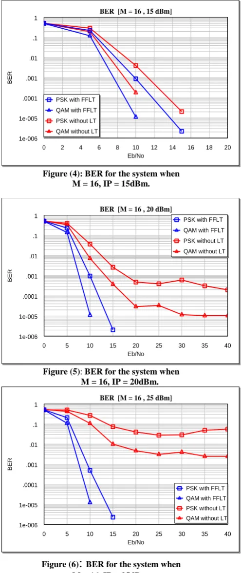
Figure (4): BER for the system when M = 16, IP = 15dBm.
Figure (5): BER for the system when M = 16, IP = 20dBm.
Figure (6)
:
BER for the system when M = 16, IP = 25dBm.0 10 20 30 40 50 60
power (dBm) AM to AM
10 20 30 40 50 60
AM to AM of PA (dBm)
AM to AM of PA after FFLT (dBm)
0 2 4 6 8 10 12 14 16 18 20
Eb/No
BER [M = 16 , 15 dBm]
1e-006 1e-005 .0001 .001 .01 .1 1
BER
PSK with FFLT
QAM with FFLT
PSK without LT
QAM without LT
0 5 10 15 20 25 30 35 40
Eb/No
BER [M = 16 , 20 dBm]
1e-006 1e-005 .0001 .001 .01 .1 1
BER
PSK with FFLT
QAM with FFLT
PSK without LT
QAM without LT
0 5 10 15 20 25 30 35 40
Eb/No
BER [M = 16 , 25 dBm]
1e-006 1e-005 .0001 .001 .01 .1 1
BER
PSK with FFLT
QAM with FFLT PSK without LT
QAM without LT
Source of Data Random
Modulations PSK , QAM
M 16, 64, 256
Number of Subcarriers 1705
Power Amplifier G = 26 , P1dB = 45 Coding Convolution with rate 1/2
Mode 2k
Subcarrier Spacing 4.464 (KHz)
Guard Interval 0.03125
[image:3.595.48.287.432.703.2]38
Figure (7): BER for the system when M = 64, IP = 15dBm.
Figure (8): BER for the system when M = 64, IP = 20dBm.
Figure (9): BER for the system when M = 64, IP = 25dBm.
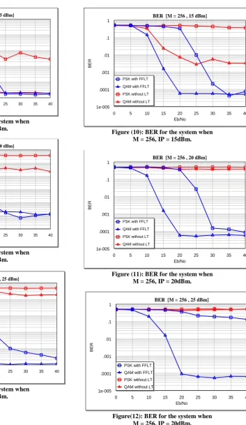
Figure (10): BER for the system when M = 256, IP = 15dBm.
Figure (11): BER for the system when M = 256, IP = 20dBm.
Figure(12): BER for the system when M = 256, IP = 20dBm.
0 5 10 15 20 25 30 35 40
Eb/No
BER [M = 64 , 15 dBm]
1e-005 .0001 .001 .01 .1 1
BER
PSK with FFLT QAM with FFLT PSK without LT QAM without LT
0 5 10 15 20 25 30 35 40
Eb/No
BER [M = 64 , 20 dBm]
1e-006 1e-005 .0001 .001 .01 .1 1
BER
PSK with FFLT QAM with FFLT PSK without LT QAM without LT
0 5 10 15 20 25 30 35 40
Eb/No BER [M = 64 , 25 dBm]
1e-005 .0001 .001 .01 .1 1
BER
PSK with FFLT QAM with FFLT PSK without LT QAM without LT
0 5 10 15 20 25 30 35 40
Eb/No
BER [M = 256 , 15 dBm]
1e-005 .0001 .001 .01 .1 1
BER
PSK with FFLT QAM with FFLT PSK without LT QAM without LT
0 5 10 15 20 25 30 35 40
Eb/No
BER [M = 256 , 20 dBm]
1e-005 .0001 .001 .01 .1 1
BER
PSK with FFLT QAM with FFLT PSK without LT QAM without LT
0 5 10 15 20 25 30 35 40
Eb/No
BER [M = 256 , 25 dBm]
1e-005 .0001 .001 .01 .1 1
BER
PSK with FFLT QAM with FFLT PSK without LT
[image:4.595.195.549.61.671.2] [image:4.595.64.359.62.631.2]39 Figure (3) shows The AM to AM conversion of the power
amplifier after and before Feedforward Linearization Technique Where the correction can be seen clearly in non-linearity.
[image:5.595.54.280.271.425.2]Figures (4 to 12) shows the simulation of BER performances for the (16, 64, and 256) QAM-PSK of OFDM system with different values of the input power (IP) (15, 20, and 25) dBm. It is noticeable that when increase the amount of the IP, the amount of BER will be increased. Also, if increased the amount of M, BER will increase and If decrease IP or M, the BER increase. This mean that the BER is depend on M and IP. It has been observed that the best result we get when be (IP = 15, M = 16), which are roughly similar to the original signal and when the (IP = 25, M = 256), we will get over the signal with high BER.
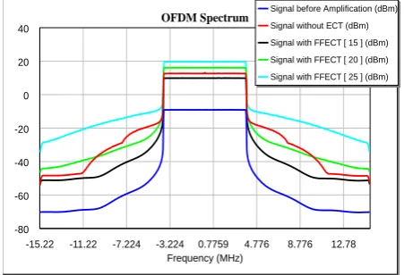
Figure 13 show the spectrum of OFDM system with different IP (15, 20, and 25) dBm.
Figure (13): The spectrum of OFDM system with different IP (15, 20, and 25) dBm.
5.
CONCLUSION
In this paper, the focus was on analyzed and simulated the effect of feedforward Linearization technique on power amplifier nonlinearity over OFDM systems. Where it was noted that when using the feedforward can be reduced the non-linearity of high power amplifier (HPA), and thus can be reduced BER and increase the efficiency of HPA, then will lead to an increase in the efficiency of OFDM system. It is also noticed that bit error rate for the power amplifier is depend on different modulation methods and IP where it is minimum for the signal modulated with Quadrature Amplitude Modulation (QAM) as compared to Phase Shift Keying (PSK) modulation and whenever the value of the IP have been less the results will be best. So signal modulated with QAM has minimum distortion in OFDM system with the least possible value for IP.
6.
REFERENCES
[1] Paloma García-Dúcar, Jesús de Mingo and Antonio Valdovinos. "Misalignments Feedforward Transmitter Correction Design for Nonlinear Distortion Cancellation in OFDM Systems". 1-4244-0063-i2006 IEEE, 2006. [2] A. Singh, H. Kaur. "Non Linearity Analysis of High
Power Amplifier in OFDM system International Journal of Computer Applications", Vol. 37– No.2, January 2012 [3] Ziad El-Khatib , Leonard MacEachern and Samy A. Mahmoud, " Distributed CMOS Bidirectional Amplifiers". Carleton University, 2012.
[4] Shawn P. Stapleton. " Amplifier Linearization Using Adaptive Digital Predistortion". Agilent Technologies, 2001.
[5] Suranjana Julius. "Design and implementation of an ETSI-SDR OFDM Transmitter with Power Amplifier Linearization". M.Sc. Thesis, University of Saskatchewan, 2010.
[6] Orthogonal Frequency Division Multiplexing (OFDM) Applications for Wireless Communications with Coding [7] Brahmaji T.A.R.K. "An efficient ICI cancellation
technique for OFDM communication systems", M.Sc. Thesis. National Institute of Technology, Rourkela, 2009.
[8] Ming Xiao." Novel Predistortion Techniques for RF Power Amplifiers". The University of Birmingham, 2009.
[9] Abilash Menon. "power amplifier linearization implementation using a field programmable gate array ".University of Massachusetts Amherst in partial fulfillment,2007.
[10] Frederick H. Raab, Peter Asbeck, Steve Cripps, Peter B. Kenington, Zoya B. Popovic, Nick Pothecary, John F. Sevic and Nathan O. Sokal. "RF and Microwave Power Amplifier and Transmitter Technologies — Part 1".From May 2003 High Frequency Electronics
[11] Tzi-Dar Chiueh and Pei-Yun Tsai. "OFDM Baseband Receiver Design for Wireless Communications". National Taiwan University, Taiwan ,2007.
[12] Marian K. Kazimierczuk, "RF Power Amplifiers", Wright State University, Dayton, Ohio, USA, 2008.
-15.22 -11.22 -7.224 -3.224 0.7759 4.776 8.776 12.78 Frequency (MHz)
OFDM Spectrum
-80 -60 -40 -20 0 20 40