Technology (IJRASET)
Performance Analysis of a Self-Activating Solar
Tracking Setup
S.P. Jena1, S.K. Acharya2, C. Deheri3
1,2,3
Department of Mechanical Engineering, S ‘O’ A University, Bhubaneswar, Odisha, India
Abstract-Solar energy is rapidly gaining acclaim and acceptance as an important, efficient and dependable means to substitute conventional energy resources. To make solar energy more viable, the efficiency of solar array systems must be maximized. A feasible approach for maximizing the efficiency of solar array system is sun tracking. In the present paper, an automatic solar tracking system is designed and constructed which offers a reliable and affordable method of aligning the solar module with the sun in order to maximise its energy output. This project also enables decentralized generation of energy which will give higher penetration in rural India where energy needs are yet to be fulfilled. The factors of photovoltaic module efficiency and electronic controlling are considered in the process of modelling to maximize the output energy and minimize the energy consumption of solar tracker. A comparison of power output between automatic solar tracking system and fixed tilt solar panel is also done. Average percentage increase in energy output of solar tracking system is found to be 22%. This investigation further provides scope for renewable energy education leading towards capacity building for extraction of higher solar energy.
Keywords: Solar tracking, Solar panels, Performance evaluation, Photovoltaic
I. INTRODUCTION
Technology (IJRASET)
dependant resistor (LDR) and compare with fixed panels based on monthly horizontal radiation data.
II. METHODOLOGY
[image:3.612.57.486.544.719.2]To investigate the effect of sun tracking mechanism on the performance of a flat plate photovoltaic system for different sky conditions, we have taken readings of seventeen completely clear sky days, eleven partially clear and three cloudy days at the geographical location of Bhubaneswar which is 20.2645˚ N and 85.8355˚ E. Out of the two panels, first one is facing north-south direction with fixed tilt angle of 5˚ and another one is tracking the sun facing at East-West direction. In this system two LDRs are fixed on the solar panel at a little distance apart from each other. LDR varies the resistance depending upon the intensity of the light falling on it. A partition of 4 inch is present between the two LDRs whose shadow is used for the change in resistance of the LDRs when the sun is not normally incident on the solar panel. The resistance of both the LDRs is changed to analog voltage signals. The analog voltage signals of both the LDRs were fed to the inbuilt analog to digital converter (ADC) of the microcontroller (ATMEGA16). Microcontroller receives the two digital signals from the ADC and compares them. The LDR signals are not equal except for normal incidence of sunlight. When there is a difference between the LDR voltage levels, the microcontroller program drives the motor towards normal incidence of sunlight. This process repeats itself after every 20 minutes. The microcontroller is programmed for the desired input and output for the desired functioning of the circuit with the help of software ‘WinAVR’. The layout diagram of electronic circuit is shown in Fig 1. The battery powers the whole circuit for all of the time is a 7.4 volt Li- ion battery. KM-SPM-11 precision pyranometer has been used to measure the global solar irradiance.
Fig 1. Layout diagram of electronic circuit.
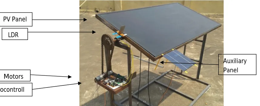
The input from this battery is fed to the voltage regulator which supplies current to the electronics parts. These batteries consist of two Li-ion cells of 3.7 V each. They have a capacity of 2000 mAh each. An auxiliary smaller solar panel is fixed to the side by the bigger panel which charges the battery continuously. Th e actual setup is sh own in Fig 2. The specifications of the photo voltaic pan el ar e given in Table 1.
PV Panel LDR
Motors Microcontroll
Technology (IJRASET)
Fig 2. Actual setup
Table 1. Specifications of the photo voltaic pan el
Model SCG55-HV-F
Dimension 1260mm x 660mm
Material CIGS (Copper, Indium, Galium, Diselenide)
Power 55W
VOC 51.5 Volt
ISC 1.7Amp
III. RESULTS AND DISCUSSION
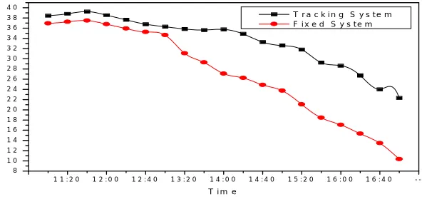
In view of the received amount of solar energy for different sky conditions, the average value of output power of both tracking system and fixed system for clear sky, partially clear sky and cloudy sky are shown in Fig 3, 4 and 5 respectively. For clear sky days throughout the day length tracking system have shown comparatively higher performance than fixed tilt system. The graph indicates that the power output of fixed tilt panel gradually decreases with time, while for tracking system the power output marginally decreases with time due to decrease in intensity of solar radiation. Similar results are obtained for average clear sky days with marginally lower average output than that of clear sky days for both sun tracking system and fixed tilt system. This indicates that automatic sun tracking system boosts the energy collection of photo voltaic pan el. It is obser ved fr om th e daily amoun ts of pr oduced electr ical en er gy, th at the increase in solar gain for East-West tracking system as compared to fixed tilt system strongly depends on climatic conditions of the location.
1 1 : 2 0 1 2 : 0 0 1 2 : 4 0 1 3 : 2 0 1 4 : 0 0 1 4 : 4 0 1 5 : 2 0 1 6 : 0 0 1 6 : 4 0 -8 1 0 1 2 1 4 1 6 1 8 2 0 2 2 2 4 2 6 2 8 3 0 3 2 3 4 3 6 3 8 4 0 P o w e r (W a tt )
T i m e
[image:4.612.157.453.371.509.2]T r a c k i n g S y s t e m F i x e d S y s t e m
Fig 3. Variation of power with time for clear sky day.
1 1 : 4 0 1 2 : 4 0 1 3 : 4 0 1 4 : 4 0 1 5 : 4 0 1 6 : 4 0
5 1 0 1 5 2 0 2 5 3 0 3 5 4 0 P o w e r (Wa tt )
[image:4.612.151.454.551.704.2]Technology (IJRASET)
1 1 :2 0 1 2 :0 0 1 2 :4 0 1 3 :2 0 1 4 : 0 0 1 4 :4 0 1 5 :2 0 1 6 :0 0 1 6 : 4 0
0 2 4 6 8 1 0 1 2 1 4
P
o
w
e
r
(W
a
tt
)
T im e
[image:5.612.144.456.99.279.2]T r a c k i n g S y s t e m F i x e d S y s t e m
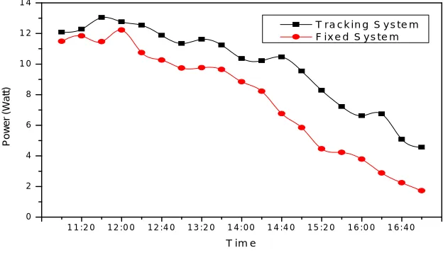
Fig 5. Variation of power with time for cloudy sky day
On cloudy days the daily collected direct solar irradiance is very small. Mainly diffused radiation and reflected radiations provide little power generation from the photo voltaic pan el. Comparatively low power output was recorded on cloudy days. Hence use of automatic sun tracking system is unnecessary during cloudy days.
IV. CONCLUSIONS
In this work, the performance of north-south fixed tilt photo voltaic pan el is compar ed with automatic east -west sun tracking syst em. The factors of photovoltaic module efficiency and electronic controlling are considered in the process of modelling to maximize the output energy and minimize the energy consumption of solar tracker. Additional amount of electrical energy produced by the photo voltaic pan el with automatic sun tr ackin g system main ly d epen ds on sk y clar ity. A comparison of power output between automatic solar tracking system and fixed tilt solar panel is done. Average percentage increase in energy output of solar tracking system is found to be 22%. The use of LDR based sun tracking system contributes considerably to increase the performance of photo voltaic pan el.
REFERENCES
[1] Koussa M., Haddadi M., Saheb D., Malek A., Hadji S. 2012, Sun tracker systems effects on flat plate photovoltaic PV systems performance for different sky states: A case of an arid and hot climate, Energy Procedia, 18: 839-850.
[2] Li G., Tang R., Zhong H. 2012, Optical performance of horizontal single-axis tracked solar panels, Energy Procedia, 16: 1744-1752. [3] Li Z., Liu X., Tang R. 2011, Optical performance of vertical single-axis tracked solar panels, Renewable energy, 36: 64-68.
[4] Huang B. J., Sun F. S. 2007, Feasibility study of one axis three positions tracking solar PV with low concentration ratio reflector, Energy Conversion and Management, 48: 1273-80.
[5] Morcos V. H. 1994, Optimum tilt angle and orientation for solar collectors in Assiut, Egypt, Renewable energy, 4: 291-298. [6] Chang T. P.2009, Performance study on east-waste oriented single axis tracked panel, Energy, 34: 1530-38.
[7] Chang T. P. 2009, The gain of single-axis tracked panels according to extraterrestrial radiation, Applied Energy, 86: 1074-79. [8] Rehman S., El-Amin I. 2012, Performance evaluation of an off-grid photovoltaic system in Saudi Arabia, Energy, 46: 451-458.