TITLE
DEVELOPMENT OF A FLICKING SYSTEM FOR PRODUCING 3-DIMENSIONAL CELLS IN MICROBEADS
WONG SOON CHUAN
A thesis submitted in
fulfilment of the requirement for the award of the Degree of Master in Electrical Engineering
Faculty of Electrical and Electronic Engineering Universiti Tun Hussein Onn Malaysia
iii DEDICATION
iv
ACKNOWLEDGEMENT
Thanks to God for all the blessings given to me, both in wisdom and health that I am able to finish this project successfully. Special thanks to my supervisor, Assoc. Prof. Dr. Soon Chin Fhong for her supports, patience and guidance given throughout the duration for this research. We acknowledge the help from Prof. Dr. Cheong Sok Ching from Cancer Research Malaysia for donating oral squamous cell carcinoma (ORL-48) cells to this research. Continuous research discussion and supports from the colleagues from Biosensor and Bioelectronics Laboratory, MiNT-SRC and FKMP, UTHM is another important factor that helps in the completion of this project. Appreciation is also extended to the lecturers or panels from FKEE who has provided constructive criticism in improving the research.
v
LIST OF ASSOCIATED PUBLICATION
Journal
1. Soon Chuan Wong, Chin Fhong Soon, Wai Yean Leong, Kian Sek Tee, “Flicking technique for microencapsulation of cells in calcium alginate leading to the microtissue formation”, Journal of Microencapsulation, Volume 33, Issue 2, Pages: 162-171, 11 February 2016. http://dx.doi.org/10.3109/02652048.2016. 1142017. Impact factor: 1.631 (Q2, JCR, ISI Indexed).
2. Soon Chuan Wong, Chin Fhong Soon, Wai Yean Leong, Kian Sek Tee, “Development of a flicking system for producing calcium alginate microbeads”, Jurnal Teknologi, Volume 78, Issue 6-2, Pages: 103-109, June 2016. http://dx.doi.org/10.11113/jt.v78.8909 (Scopus Indexed).
vi
Conference proceeding
vii
LIST OF AWARD
1. Gold Medal in Research & Innovation Festival 2015 (UTHM), “A novel flicking system for producing high throughput 3D cells”, 16 – 17th November 2015, Universiti Tun Hussein Onn Malaysia.
2. Bronze Medal in Malaysia Technology Expo (MTE) 2016,
“A novel flicking system for producing high throughput 3D cells”,
18 – 20th February 2016, Putra World Trade Centre, Kuala Lumpur, Malaysia.
PATENT FILING
1. In the process of patent filing. (Patent pending)
viii
ABSTRACT
ix
ABSTRAK
x
CONTENTS
TITLE i
DECLARATION ii
DEDICATION iii
ACKNOWLEDGEMENT iv
LIST OF ASSOCIATED PUBLICATION v
LIST OF AWARD vii
ABSTRACT viii
CONTENTS x
LIST OF TABLES xv
LIST OF FIGURES xvi
LIST OF SYMBOLS AND ABBREVIATIONS xxii
LIST OF APPENDICES xxv
CHAPTER 1 INTRODUCTION 1
1.1 Overview 1
1.2 Research background 1
1.3 Problem statement 4
1.4 Objectives of the research 5
1.5 Scope of research 5
1.6 Thesis outline 5
CHAPTER 2 LITERATURE REVIEW 7
2.1 Introduction 7
2.2 Cell and tissue 7
2.3 Human keratinocytes 10
xi 2.5 Extracellular matrix (ECM) and cell adhesion 13
2.6 Phases of cell growth 15
2.7 Rationale to generate 3D cells 16
2.8 Previous methods for growing 3D cells 17
2.9 Microencapsulation 19
2.10 Different methods of microencapsulation 22
2.10.1 Simple dripping 22
2.10.2 Microfluidic 22
2.10.3 Electrostatic 23
2.10.4 Vibration technique 24
2.10.5 Jet cutter 25
2.10.6 Rotating disc and rotating nozzle atomiser 27 2.10.7 The summary of different microencapsulation 29
methods
2.11 Biopolymers used for microencapsulation of cells 30
2.12 Characterisation methods 32
2.12.1 Phase contrast microscopy 32
2.12.2 Field emission scanning electron microscope 33 (FE-SEM)
2.12.3 Fourier transform infrared spectroscopy (FTIR) 35 2.12.4 4′,6-Diamidino-2-phenylindole dihydrochloride 36 (DAPI) staining
2.12.5 Live/dead viability assay 37
CHAPTER 3 METHODOLOGY 38
3.1 Introduction 38
3.2 Overview of the research methodology 38
3.3 Overall architecture of the flicking system 42
3.3.1 Design of the flicking device 46
3.3.1.1 Circuit design of the flicking device 48 3.3.1.2 Program flow for the flicking device 51 3.3.2 Design the infusion pump of the flicking 57
xii 3.3.2.1 Circuit design of the infusion pump 59 3.3.2.2 Program flow for the infusion pump 63 3.4 Performance assessment of the flicking system 67 3.4.1 Verify the PWM signals generated by the 67
circuit of flicking device
3.4.2 Investigate the relationship of the 67 potentiometer voltage to the PWM signals
3.4.3 Investigate the effect of PWM signals to 68 motor speed
3.4.4 Flow rate calibration of the commercial syringe 68 pump and the customised infusion pump
3.5 The setup of the flicking experiment 69
3.6 Investigating the effects of flow rate and flicking 70 speed to the size of the microbeads
3.7 Microencapsulation of cells using the developed 71 flicking system
3.7.1 Cell culture of HaCaT and ORL-48 71 3.7.2 Microencapsulation of cells and monitoring 72 3.8 Characterising the biochemistry and surface 73
structure of the microbeads
3.8.1 FTIR scanning of the calcium alginate 73 microbeads with and without cells
3.8.2 FE-SEM scanning of the calcium alginate 73 microbeads
3.9 Characterising the biochemistry properties of the 3D
microtissues 73
3.9.1 DAPI staining 73
3.9.2 Live and dead cells staining 74
3.9.3 Extraction of 3D microtissues from 74 calcium alginate
3.9.4 FE-SEM scanning of the extracted 3D 75 microtissues
xiii
CHAPTER 4 RESULTS AND DISCUSSION 76
4.1 Introduction 76
4.2 The functions of flicking system 76
4.3 Assessment of the flicking system performance 79
4.3.1 Verification of PWM signals 79
4.3.2 The relationship of potentiometer voltage 81 to the PWM signals
4.3.3 Effect of PWM signals on motor speed 82 4.3.4 Battery level indication of the flicking 83
device
4.3.5 Flow rate calibration of the commercial 84 syringe pump (New Era NE-4002X)
4.3.6 Flow rate calibration of the customised 85 infusion pump
4.4 The effects of flow rate and flicking speed to 86 the size of microbeads
4.4.1 The effects of different flow rates to the 86 size of microbeads
4.4.2 The effects of different flicking speeds to 93 the size of microbeads
4.5 Microencapsulation of HaCaT and ORL-48 cells 98 at different cell densities
4.5.1 HaCaT cells encapsulation at a cell density 98 of 1.75 × 10⁶ cells/ml
4.5.2 HaCaT cells encapsulation at cell density 99 of 31.9 × 10⁶ cells/ml
4.5.3 ORL-48 cells encapsulation at cell density 101 of 3.97 × 10⁶ cells/ml
4.5.4 ORL-48 cells encapsulation at cell density 102 of 94.2 × 10⁶ cells/ml
4.6 The biochemistry and surface structure of 104 the microbeads
xiv 4.6.2 The surface morphology of the microbeads 107 4.7 The biophysical properties of the 3D microtissues 108 4.7.1 Nucleus staining of the encapsulated 108
HaCaT and ORL-48 cells
4.7.2 The viability of the encapsulated 111 HaCaT and ORL-48 cells
4.7.3 3D microtissue extracted from calcium 112 alginate microbeads
4.7.4 The surface morphology of the 3D 113 microtissues
4.7.5 Spread of cells in microtissue replating 115 experiment
CHAPTER 5 CONCLUSION 118
5.1 Conclusion 118
5.2 Thesis contribution 119
5.3 Recommendations for future work 119
REFERENCES 121
APPENDIX 134
xv
LIST OF TABLES
2.1 Summary of 3D cell culture systems 18
2.2 Application of encapsulation and target of encapsulation 21 2.3 Comparison of six microencapsulation techniques on their
capabilities
30
2.4 Common biopolymers used for microencapsulation of cells and their applications
32
3.1 Establishment of experiments 41
3.2 The relationship between “mode” and communication lines data
65
xvi
LIST OF FIGURES
2.1 The anatomy of human cell 8
2.2 Human body tissues 10
2.3 Layers of the epidermis 11
2.4 Monolayer of HaCaT cells cultured in a petri dish (Scale bar: 100 µm)
12
2.5 Monolayer of ORL-48 cells cultured in a petri dish (Scale bar: 100 µm)
13
2.6 Integrin-mediated cell adhesion to the ECM. (a) Suspension cell adhere to the surface of ECM. (b) The structures of ECM
14
2.7 Different phases of cell growth 15
2.8 The five main structural forms of microcapsules 20 2.9 Calcium alginate beads formation by simple dripping 22 2.10 Calcium alginate microbeads formation by microfluidic
device
23
2.11 Calcium alginate microbeads formation by electrostatic 23 2.12 Apparatus for producing calcium alginate beads by the
vibration method, comprising a syringe pump for forcing sodium alginate solution from a syringe, a loudspeaker, and a sine wave sound generator
24
2.13 Arrangement of nozzle and cutting tool, with 48 stainless steel wires
25
2.14 Scheme of the cutting process 26
xvii 2.16 Scheme of the rotating disc and nozzle technology for bead
production
27
2.17 Bead formation by a rotating disc device 28
2.18 Bead formation by a rotating nozzle device 28
2.19 The molecular structure of calcium alginate 31
2.20 The working principal of Phase Contrast Microscope 33 2.21 FE-SEM (Jeol, JSM – 7600F) in Microelectronic and
Nanotechnology - Shamsuddin Research Center, Universiti Tun Hussein Onn Malaysia
34
2.22 A FTIR spectrometer (Perkin Elmer Spectrum 100) 35 2.23 Chemical structure of 4'-6-diamidine-2-phenylindole
(DAPI) dichloride
36
3.1 Flow chart of research methodology 40
3.2 Two major parts of the flicking system 42
3.3 The architecture sketchup of the flicking system (front side) 42 3.4 The architecture sketchup of the flicking system (back side) 43
3.5 Control panel of the flicking system 44
3.6 Infusion pump of the flicking system 44
3.7 Flicking device of the flicking system 45
3.8 The block diagram of flicking device circuit 46
3.9 The layout of the flicking device and controller circuit 47 3.10 The flicking device was used with a conventional syringe
pump (New Era NE-4002X) to generate Ca-Alg microbeads during the preliminary work
47
3.11 The overall schematic diagram of the flicking device 50 3.12 Programming flow chart of the flicking device 52 3.13 Coding of custom character 1, head of battery bar (filled) 53 3.14 Coding of custom character 2, head of battery bar (hollow) 53 3.15 Coding of custom character 3, middle of battery bar (filled) 53 3.16 Coding of custom character 4, middle of battery bar
(hollow)
xviii 3.17 Coding of custom character 5, end of battery bar (filled) 54 3.18 Coding of custom character 6, end of battery bar (hollow) 54
3.19 Coding to read the remaining battery level 55
3.20 Coding to read the communication data from the Arduino of infusion pump
56
3.21 Coding to start or stop the flicking device 57
3.22 The block diagram of infusion pump circuit 58
3.23 The preliminary design of the infusion pump with a temporary casing
59
3.24 The overall schematic diagram of the infusion pump 60 3.25 The communication connections between Arduino ARD1
(flicking device) and Arduino ARD2 (infusion pump)
62
3.26 Programming flow chart of the infusion pump 64
3.27 Coding used to select the speed of infusion pump 65 3.28 Coding used to create the low, middle and high pulse
frequency and output the speed of infusion pump to the flicking device for display on the LCD
66
3.29 The experimental setup to generate calcium alginate microbeads
70
4.1 Front view of the flicking system prototype 77
4.2 Top view of the flicking system prototype 77
4.3 Flicking motor of the flicking system prototype 78
4.4 LCD display of the flicking system prototype 78
4.5 The output signals of PWM at different duty cycles: (a) 0 % duty cycle, (b) 25 % duty cycle, (c) 50 % duty cycle, (d) 75 % duty cycle and (d) 100 % duty cycle
80
4.6 The relationship between the potentiometer input voltage and duty cycle of PWM signal
81
4.7 Graph of motor speed versus duty cycle of PWM 82
4.8 (a) High, (b) middle, (c) low and (d) extremely low battery levels
xix 4.9 Syringe pump (New Era NE-4002X) flow rates verification
result
84
4.10 Customised infusion pump flow rates verification 85 4.11 One of the microbeads sample generated by flow rates: (a)
5, (b) 10 and (c) 15 µl/min (Scale bar: 100 µm)
87
4.12 The size distribution graph of microbeads produced at different flow rates of (a) 5, (b) 10 and (c) 15 µl/min
88
4.13 Size distribution of calcium alginate microbeads in different flow rates (5, 10, 15 µl/min)
89
4.14 Some of the microbeads sample generated by flow rates: (a) 2 µl/min, (b) 4 µl/min, (c) 6 µl/min, (d) 8 µl/min and (e) 10 µl/min (Scale bar: 200 µm)
91
4.15 The size distribution graph of microbeads produced at different flow rates of (a) 2, (b) 4, (c) 6, (d) 8 and (e) 10 µl/min
92
4.16 Size distribution of calcium alginate microbeads in different flow rates (2, 4, 6, 8, 10 µl/min)
93
4.17 Some of the microbeads sample generated by flicking speeds: (a) 60, (b) 70, (c) 80, (d) 90 and (e) 100 rpm (Scale bar: 200 µm)
95
4.18 The size distribution graph of microbeads produced at different flicking speed of (a) 60, (b) 70, (c) 80, (d) 90 and (e) 100 rpm
96
4.19 Size distribution of calcium alginate microbeads in different flicking speeds
97
4.20 HaCaT cells in calcium alginate with cell density of 1.75 × 10⁶ cells/ml after: (a) day 1, (b) day 3 and (c) day 6 of culture (Scale bar: 100 µm)
98
4.21 HaCaT cells protrusion from the microbead (Scale bar: 100 µm)
xx 4.22 HaCaT cells in calcium alginate with cell density of 31.9 ×
106 cells/ml after: (a) day 1, (b) day 3, (c) day 5, (d) day 7, (e) day 9, (f) day 11, (g) day 13 and (h) day 15 of culture (Scale bar: 100 µm)
100
4.23 ORL-48 cells in calcium alginate with cell density of 3.97 × 10⁶ cells/ml after: (a) day 1, (b) day 3 and (c) day 6 and (d) day 9 of culture (Scale bar: 100 µm)
101
4.24 ORL-48 cells in calcium alginate with cell density of 94.2 × 10⁶ cells/ml after: (a) day 1, (b) day 3, (c) day 5, (d) day 7, (e) day 9, (f) day 11, (g) day 13 and (h) day 15 of culture (Scale bar: 100 µm)
103
4.25 FTIR spectra of (a) calcium alginate, (b) HaCaT cells and (c) calcium alginate encapsulated with HaCaT cells
106
4.26 Morphology image of calcium alginate microbead with different magnification: (a) ×150 (Scale bar: 100 µm), (b) ×300 (Scale bar: 10 µm) and (c) ×10000 (Scale bar: 1 µm)
107
4.27 DAPI staining on HaCaT cells in calcium alginate: (a) after 3 days cultured (white light), (b) after 3 days cultured (fluorescence), (c) after 9 days cultured and (d) after 15 days cultured. (Scale bar: 100 µm)
109
4.28 DAPI staining on ORL-48 cells in calcium alginate: (a) after 3 days cultured, (b) after 9 days cultured and (c) after 15 days cultured. (Scale bar: 100 µm)
110
4.29 Live and dead staining on 3D HaCaT cells encapsulated in calcium alginate microbead: (a) sample 1 and (b) sample 2. (Scale bar: 100 µm)
112
4.30 The images of microtissues after extraction: (a) HaCaT microtissue before and (b) after alginate lyased, (c) ORL-48 microtissue before and (d) after alginate lyased (Scale bar: 100 µm)
113
xxi magnifications: (a) ×150 (Scale bar: 100 µm), (b) ×300
(Scale bar: 10 µm) and (c) ×1500 (Scale bar: 10 µm)
4.32 FE-SEM image of 3D ORL-48 microtissue with different magnifications: (a) ×150 (Scale bar: 100 µm), (b) ×300 (Scale bar: 10 µm) and (c) ×1500 (Scale bar: 10 µm)
115
4.33 Monitoring of replated 3D HaCaT microtissue on: (a) day 1, (b) day 2, (c) day 3 and (d) day 4 (Scale bar: 100 µm)
116
4.34 Monitoring of replated 3D ORL-48 microtissue on: (a) day 1, (b) day 2, (c) day 3 and (d) day 4 (Scale bar: 100 µm)
xxii
LIST OF SYMBOLS AND ABBREVIATIONS
% - Percent sign
- Pulse duration
o
C - Degree Celsius
2D - Two dimensional
3D - Three dimensional
BSC - Biological safety cabinet Ca-Alg - Calcium alginate
cm - Centimeter
CO2 - Carbon dioxide
DAPI - 4′,6-Diamidino-2-phenylindole dihydrochloride
DC - Direct current
DMEM - Dulbecco‟s modified eagle medium DNA - Deoxyribonucleic acid
ECM - Extracellular matrix ER - Endoplasmic reticulum ETFE - Ethylene tetrafluoroethylene EthD-1 - Ethidium homodimer-1
FDA - Food and Drug Administration
FE-SEM - Field emission scanning electron microscope FITC - Fluorescein isothiocyanate
FTIR - Fourier transform infrared spectroscopy H & E - Hematoxylin and eosin
HA - Hyaluronic acid
xxiii HBSS - Hank‟s balanced salt solution
Hz - Hertz
kg-cm - Kilogram per centimeter
LABE - Low Angle Backscatter Imaging LCD - Liquid crystal display
LEI - Lower Secondary Electron Image MiNT-SRC - Microelectronic and Nanotechnology –
Shamsuddin Research Center mg/ml - Miligram per mililiter
min - Minute
ml - Mililiter
mm - Milimeter
nm - Nanometer
ORL-48 - Oral squamous cell carcinoma cell line OSCC - Oral squamous cell carcinoma
PAA - Poly(acrylic acid) PAam - Polyacrylamide PCB - Printed circuit board PCL - Poly(ε-caprolactone)
PDMAEM - Poly(dimethylaminoethylmethacrylate) hydrochloride PEG - Poly(ethylene glycol)
PGA - Polyglycolide
PLA - Polylactide
PLAGA - Poly(lactic acid-glycolic acid) PLGA - Poly(l-lactide-co-glycolide) PLLA - Poly(L-lactic acid)
xxiv
PWM - Pulse width modulation RNA - Ribonucleic acid rpm - Revolutions per minute
SD - Standard deviation
SEI - Secondary Electron Image SEM - Scanning electron microscope
µl - Microliter
µl/min - Microliter per minute
µm - Micrometer
µM - Micromolar
UK - United Kingdom
US - United States
USA - United States of America
UTHM - Universiti Tun Hussein Onn Malaysia
V - Volt
xxv
LIST OF APPENDICES
APPENDIX TITLE PAGE
1. CHAPTER 1
INTRODUCTION
1.1 Overview
Microbeads or microcapsules have wide applications in biomedical engineering field that include drug delivery, encapsulation of biomolecules, tissue padding and tissue regeneration. General information concerning microbeads or microcapsules is briefly illustrated in the research background. The problem statement highlights the weakness of current methods to fabricate microbeads. Consequently, a method which is very simple, reliable and uses cheap materials available in the lab was introduced to generate microbeads. Nonetheless, this chapter also covers the objectives of the research, scope of research and thesis outline.
1.2 Research background
2
for high-throughput screening of drugs and for pharmacokinetic analyses of drugs [2]. For example, one man was brain dead and another five people were in hospital after an experimental drug was administered to 90 people in a French clinical trial, as reported by British Broadcasting Corporation (BBC) on 15 January 2016. This incident revealed the vital of using alternative tissue models with more availability for experimental drug trial might avoid sacrifice of life.
Various in vitro methods had been developed to culture microtissues. The most common method to culture microtissue is culturing cells on scaffolds of biopolymers that can be produced using electrospinning, salt leaching and ice particle leaching method [3]. With this method, the cells are scattered in the pores of the scaffolds. Culturing cells on a planar compliant substrate such as a hydrogel produces low yield and inconsistent size of microtissues. This technique is arguably because it is different from the actual biological microenvironment in the tissue [4]. Alternatively, microtissue can be cultured by using microencapsulation technique that allows a compound (cells) to be encapsulated inside a tiny spheroid known as microsphere or microbead, having an average diameter as small as one micro meter to several hundred micro meters [5]. Microencapsulation of cells in the calcium alginate microbeads is leading to the formation of microtissues (multicellular spheroids) [6, 7]. The unique advantage of this technique is that cell culture is performed within a 3D environment that completely surrounds cells and enabling the delivery of intense signals to cells from all directions [8]. Compared to the 2D monolayer cell culture, 3D microtissue models mimic the cell structural organisation in the in vivo system and the cellular microenvironment established in the 3D models often plays a more significant role in cellular responses to drugs and disease progression [2].
3
[9]. The capsule must be mechanically stable and easy to handle. These requirements may be fulfilled by controlling the size and thickness of the encapsulating polymer membrane at microscale range.
Microcapsules are spherical particles containing a core substance with the size varying between 50 nm to 2 mm [10]. During the early days in the 80‟s, microencapsulation technologies were used for the microencapsulation of drugs and liquidified food [11, 12]. Later in the 90‟s, this technology was discovered with new application in tissue engineering [13]. In tissue engineering, microcapsules of sodium alginate for microencapsulation of cells have the potential for the application in immunoisolatory and biochemical assays [14]. Biomaterials for microencapsulation of cells play a major roll to determine the fate of the cells encapsulated and also the proliferation of cells. There are various types of materials used to produce microcapsules such as agarose, collagen, alginate, chitosan and gelatin [15]. Sodium alginate has been found suitable for biotechnology and biomedical applications mainly as a material for the encapsulation of different cells for biochemical processing and immunoisolatory while the cells can still maintain viability within the hydrogel [14]. It has been employed for encapsulating cells to be transplanted, since it is biocompatible both to the host and enclosed cells [8].
4
be characterised using microscopy observation, FTIR scanning, Field Emission Scanning Electron Microscope (FE-SEM), DAPI staining, live and dead stainings and 3D microtissues replating. The backbone of this study is to be useful for generating the 3D microtissues, which is identified to be relevant to drive major innovations in tissue engineering.
1.3 Problem statement
The microbeads of calcium alginate can be easily generated by extruding droplets of sodium alginate solution in air using a syringe and allowed to polymerised in the calcium chloride solution. However, the extrusion technique provided limited control over the size of the microbeads and usually large beads of calcium alginate in millimeter size were produced. Small calcium alginate beads in a few hundreds of micron are desirable because this range of microbeads provide higher mechanical strength, easier implantation, better transport of oxygen and nutrients for the cells [26]. Although alginate beads can be fabricated by using microfluidic approach in micron size, the alginate microbeads formed based on microemulsion technique were covered with oil film and hence, post cleaning process is required to remove the oil film before incubating the cells. The oil film can be sealing the gas from the cells in encapsulation. Strong mechanical and chemical treatments are required to remove the immiscible fluid, which prolongs exposure of the cells to divalent ions or solvents which may harm and kill the cells [27]. Other methods such as microextrusion techniques assisted by electrostatic field and electrospraying were shown to decrease the alginate drop size. However, these methods required sophisticated high power circuit to create atomization of alginate droplets which is dangerous with electric shock hazard [20, 28].
5
1.4 Objectives of the research
The aim of the research is the development of a flicking system for producing 3D cells in microbeads leading to the growth of microtissues. Four objectives were outlined to achieve the aim:
a) To develop a flicking system to produce calcium alginate microbeads size in 200 to 300 micron.
b) To investigate the effects of infusion pump flow rates and flicking motor speed to the size of the microbeads produced.
c) To microencapsulate cells using the developed flicking system.
d) To characterise the biophysical properties of the 3D microtissues formed in calcium alginate microbeads.
1.5 Scope of research
This research was divided into four scopes which are:
a) Design and development of a mechatronic system of microextrusion system with a flicking device (flicking system).
b) Determining the syringe flow rates and flicking speed of the system to encapsulate cells in the appropriate microbeads size.
c) Encapsulating human keratinocyte cell lines (HaCaT) and oral squamous cell carcinoma (ORL-48) cells in the calcium alginate microbeads.
d) Monitoring the growth of the microencapsulated cells into microtissues.
1.6 Thesis outline
6
2. CHAPTER 2
LITERATURE REVIEWS
2.1 Introduction
This chapter has included the summarised information of the relevant studies on cells microencapsulation leading to microtissues formation in the calcium alginate microbeads. The literature review covered the fundamental knowledge of cell and tissue, microencapsulation techniques and techniques used for biophysical characterisation of microtissues are discussed in the following subchapters which are cell and tissue, extracellular matrix (ECM), cell adhesion, phases of cell growth, microencapsulation, different technology of microencapsulation, biopolymer used for microencapsulation of cells, rationale to generate 3D cells, inverted phase contrast microscopy, field emission scanning microscope (FE-SEM), fourier transform infrared spectroscopy (FTIR), DAPI staining and live/dead viability assay.
The sources of the literatures reviewed are journals, articles, and information from books and internet, which are important on identifying problems as well as give ideas in this research.
2.2 Cell and tissue
8
[image:32.612.122.533.334.652.2]of cytoplasm enclosed within a membrane, which contains many biomolecules such as nucleic acids and proteins [29]. Organisms can be classified as unicellular (cell and bacteria) or multicellular (plants and animals). Human has about 100 trillion (1014) cells while the number of cells in plants and animals varies from species to species [30]. Most animal and plant cells are in dimensions between 1 and 100 micrometres and only can be visible under the microscope [31]. The cells build the structure of body, consume nutrients from food, convert those nutrients into energy, and carry out specialist functions. Organelles are structures that perform specialised tasks within the cell. These organelles containing in the cytoplasm are such as pinocytotic vesicle, golgi vesicles, cytoskeleton, endoplasmic reticulum (ER), golgi apparatus, lysosomes, mitochondria, centrioles, microtubules, nucleus, nucleolus, plasma membrane and ribosomes as shown in Figure 2.1.
Figure 2.1: The anatomy of human cell [32] Centriole
(within centrosome) Lysosome
Golgi apparatus (Golgi body)
Nucleus
Nucleus membrane Genetic material (DNA)
Nucleolus Endoplasmic reticulum
Ribosomes
9
Cytoplasm is a jelly-like fluid which surrounds the cell‟s organelles and nucleus. The cytoskeleton is a chain of long fibers that build up the cell‟s structural framework that has several critical functions, allowing cells to move, cell division and determining cell shape. In addition, cytoskeleton provides a track-like system that directs the movement of organelles and other substances within cells. The endoplasmic reticulum is responsible in molecule processing and transport to their specific destinations either outside or inside the cell. Nonetheless, the golgi apparatus is responsible in packaging molecules for export from the cell. Lysosomes destroy toxic substances and recycle exhausted cell parts. In addition, mitochondria provide the energy for cells to replicate themselves with their own genetic material. Ribosomes use the cell‟s genetic instructions to make proteins at the same time. Besides that, the nucleus contains most of the cell‟s genetic material such as RNA (ribonucleic acid) and DNA (deoxyribonucleic acid). The plasma membrane is the outer most layer which enclosed the cell and allows the transport of materials to leave and enter the cell.
10
Figure 2.2: Human body tissues [33]
2.3 Human keratinocytes
The epidermis is made of squamous epithelium that forms the protective layer of the skin [34]. Keratinocytes are the main cell type in the epidermis layer. Epidermis consists of five histologically distinct cellular layers such as stratum corneum, stratum lucidum, stratum granulosum, stratum spinosum and stratum basale as shown in Figure 2.3. Stratum spinosum is the layer with the most human keratinocytes in the epidermis. Human keratinocytes cell line (HaCaT) is transformed immortal keratinocyte cell line with abnormal chromosomes number from adult human skin that has been widely used for scientific research, studies of cell biology and differentiation. HaCaT cells are
Connective tissue
Skeletal muscle
Epithelial tissue Smooth muscle
Nervous tissue
11
[image:35.612.115.538.284.574.2]utilised for their high capacity to proliferate and differentiate in vitro [35]. HaCaT cells have reduced tissue proliferation and regeneration compared to normal epidermal keratinocytes [36, 37]. By the addition of growth factors can stimulate the proliferation rate of HaCaT cells [38], the characterisation of human keratinocyte using this model becomes reproducible and overcome the short culture lifespan issue of normal human keratinocyte. Figure 2.4 shows a phase contrast photomicrograph of HaCaT cells in monolayer of culture. In monolayer or 2D structure, HaCaT cells are displayed with polygonal shape and tightly coupled to the neighbouring cells when grown into confluency.
Figure 2.3: Layers of the epidermis [39] Stratum corneum
Stratum lucidum Stratum granulosum
Stratum spinosum
Stratum basale Melanocyte
Dermis
Dead cells filled with keratin
Lamellar granules
Keratinocyte
12
Figure 2.4: Monolayer of HaCaT cells cultured in a petri dish (Scale bar: 100 µm)
2.4 Oral squamous cell carcinoma cell line (ORL-48)
Oral cancer is a common disease and silent killer in the developing country, especially in
Southeast Asia country. Microtissue models of cancer cells are necessary in drug
discovery and the cancer research. Oral squamous cell carcinoma (OSCC) cell line
(ORL-48) was established by Cancer Research Malaysia. They are surgically explanted
epithelial specimens obtained from untreated primary human oral carcinoma cell in the
squamous layer of the oral cavity. These epithelial cells were genetically modified to be
immortal and grown into monolayer with doubling times ranging between 26.4 and 40.8
13
Figure 2.5: Monolayer of ORL-48 cells cultured in a petri dish (Scale bar: 100 µm)
2.5 Extracellular matrix (ECM) and cell adhesion
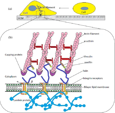
Extracellular matrix (ECM) is made up of polysaccharides and proteins, including laminins, collagens, elastins, proteoglycans and fibronectins, all secreted by the cell [41]. In animal cells, the ECM enclosed cells as fibrils that contact the cells [42]. Cells in animals are also joined directly to each other by cell adhesion proteins at the cell surface. In addition, ECM provides a biochemical barrier, mechanical support and a medium for extracellular communication that is assisted by cell adhesion proteins, moreover ECM provides tensile strength for tendons, compressive strength for cartilage, hydraulic protection for cells and elasticity to the walls of blood vessels [42].
14
[image:38.612.127.533.200.597.2]two different chains, the α (alpha) and β (beta) subunits [46]. During cell-ECM adhesion, the specific ligands in the ECM decide the type of α and β subunits of the integrins being attached by the cell [47]. There are numerous integrins exist on the cell membrane and they work collaboratively with the cell adhesion proteins in cell-ECM adhesion [48].
Figure 2.6: Integrin-mediated cell adhesion to the ECM. (a) Suspension cell adhere to the surface of ECM. (b) The structures of ECM [49]
(a)
15
2.6 Phases of cell growth
[image:39.612.114.531.477.710.2]A regular growth curve for cultured cells displayed a sigmoid pattern of proliferation. The growth phases correlative with normal cells are divided into lag phase, logarithmic growth phase, stationary (or plateau) phase and decline phase as shown in Figure 2.7. It was vital to understand the growth characteristics of the cell line because any change in cellular growth can represent a significant problem of the cell line and affect the experimental results [50]. At lag phase, the cells do not divide but adapting to the culture conditions and the length of this phase will depend upon the growth phase of the cell line at the seeding density and time of subculture. During log growth phase, the cells actively proliferate and exponentially increase in cell density. The cell population is considered to be the most viable at this phase, therefore it was recommended to assess cellular function at this stage. Each cell line will show different cell proliferation kinetics during the log phase, therefore it is the optimal phase for determining the population doubling time [50]. After the log phase, the cellular proliferation slows down due to the cell population becoming confluent at stationary phase. Ultimately, the cell death predominates in this death phase and there will be a reduction in the number of viable cells. Cell death was not due to the reduction in nutrient supplements but the natural path of the cellular cycle.
Figure 2.7: Different phases of cell growth [50]
Log N
umber
of Ce
ll
s
Lag Log
Stationary
/ Plateau Death
Live Total
16
2.7 Rationale to generate 3D cells
In the in vitro or two-dimensional (2D) culture, cells are tightly spread and coupled to the bottom surface of culture flask which is contrarily to cells that retain in-vivo [4]. The extracellular matrix components, cell-to-cell and cell-to-matrix interaction that are important for proliferation, differentiation and cellular functions in vivo are lost in the conventional 2D culture [51].
Cell to cell interaction in 2D culture is mainly concentrated at the boundary of the flattened cells [52]. Cells grown in 2D spread involuntarily by producing limited amount of extracellular matrix proteins due to the contactless spreading of cells [53]. The spatial organisation of the cells in 2D is distorted compared with the three-dimensional (3D) tissue in-vivo [54].
3D cells are good models as “near-to-in vivo” systems and reveal useful insights from a variety of ways [54]. 3D cell model is a cost effective screening platform for drug development and testing, simultaneously provides a better and more realistic predictive value for risk and safety assessment [54].
A major benefit of the 3D over the 2D culture is the decrease in the gap between cell cultures system and the cellular physiology [54]. Several researches show that 3D organisation of cells reveals more novel and surprising visions into the tumorigenesis mechanism which could represent an integral missing component in the in vitro cancer studies [55].
Thus, 3D cell culture is believed to have better similarity to the actual tissue model for cancer cell research because 3D culture restore specific morphological and biochemical features similar to the corresponding tissue in-vivo [56].
Besides that, modelling the complexity of cancer utilising these cell lines on standard plastic substrate does not accurately represent the tumour microenvironment [57]. However, tumour cells cultured in 2D monolayer conditions do not respond to cancer therapeutics [57]. Thus, 3D cells culture is useful for drug testing on cancer tumour.
17
response, precisely characterises the disease and mimics the tumour microenvironment in human body [58]. Other than that, the applications of 3D cell are differentiation studies, drug discovery and pharmacological applications, cancer research, gene and protein expression studies [59].
2.8 Previous methods for growing 3D cells
3D cells culture exhibits features that are closer to the complex in vivo conditions and the 3D culture models have proven to be more realistic for translating the study findings for in vivo applications [59].
Various in vitro methods had been developed for growing 3D cells as shown in Table 2.1. While each method presents its unique factors, the appropriate method must be selected to meet the requirements for the specific type of cells in different applications.
The most common method to culture microtissue is culturing cells in suspension such as hanging drop method. With this method, the cells are scattered in the suspension media with limited flexibility. It is not a safe to use when one is dealing with extremely pathogenic organisms as the user can easily get an infection.
Matrigel, Extracel and AlgiMatrix are the common methods used to culture 3D microtissues on substrate. Culturing cells on a planar compliant substrate produces low yield and inconsistent size of microtissues.
18
Table 2.1: Summary of 3D cell culture systems [60]
3D cell culture systems Pros Cons Methods
3D spheroids grown in suspension.
No added materials Consistent spheroid formation; control over size
Co-cultures possible Transparent
High-throughput screening capable; compatible with liquid handling tools Inexpensive
No support or porosity
Limited flexibility Size of spheroid
limiting
Magnetic cell levitation [4] and hanging drop [61]
3D spheroids grown on matrix.
Large variety of natural or synthetic materials
Customisable Co-cultures possible Inexpensive
Gelling mechanism Gel-to-gel variation
and structural changes over time Undefined
constituents in natural gels May not be transparent High-throughput screening options limited Hydrogel [3], Matrigel, Extracel and AlgiMatrix [62]
3D spheroid grown within matrix.
Large variety of materials possible for desired properties Customisable Co-cultures possible Medium cost
Possible scaffold-to-scaffold variation May not be
transparent
19
2.9 Microencapsulation
Vincenzo Bisceglie was the first to encapsulate cells using polymer membranes in 1933 [63]. Based on Bisceglie‟s work, Thomas Chang proposed the idea of encapsulating cells within ultra thin polymer membrane microcapsules to provide immunoprotection to the cells and introduced the term "artificial cells" to define this concept of bioencapsulation in 1964 [64]. Microcapsule, microsphere or microbead are similar terms that is defined as a spherical particle containing a core substance with a size between 50 nm to 2 mm [10]. However, microcapsules may not be spherical structurally but are referred to empty particles made of hydrogel (Figure 2.8). Many researches were worked on microspheres and microcapsules for the applications of controlled drug release formulations. They have been proven suitable for many applications which can be produced from natural or synthetic materials, but they are usually found in nature, for example, microencapsulation is also a natural phenomenon as what we can observe in the bacterial spores, plants seeds and egg shells [65].
20
[image:44.612.114.536.134.459.2]microcapsules that can be polynuclear, mononuclear or solid particle encapsulation and they are commonly used in the pharmaceutical and food industry [70].
Figure 2.8: The five main structural forms of microcapsules [65]
The microencapsulation technology has been applied to biotechnological and medical disciplines recently such as the encapsulation of mammalian cells [71], implantation of cells [72] and encapsulation of recombinant therapeutic proteins [73]. There are six main applications of microencapsulation within a membrane compared to its non-encapsulated form as shown in Table 2.2 with the examples of where the process was implemented.
A. Single-core B. Multi-shell C. Multi-core
21
Table 2.2: Application of encapsulation and target of encapsulation [65] [65] Application of encapsulation Target of encapsulation Protection or stabilization of the encapsulant from
interactions with reactive environments or future surroundings
Cells (Prevention)
Mammalian (immuno-response and cell damage due to agitation and aeration)
Yeast (ethanol toxicity) Enzymes
Improved stability and reactivity Prevent denaturing
Food additives and bioactives Off-setting loss and deterioration by:
High temperature food processing passage through the GI tract hygroscopicity
evaporation (aroma compounds) oxidation
Recombinant proteins
Improved stability and protection Sustained, controlled or timed release of the core
material
Agrochemicals (delivery of fertilizers, repellents, herbicides, fungicides, etc.)
Folic acid (controlled release) Pharmaceuticals (controlled delivery) Antibody (sustained release)
Adhesive (dispensed upon pressure) Butan-1-ol flavour (delayed release) Fragrances (dispensed upon pressure) Targeting of encapsulated compounds to specific
sites
DNA to phagocytic cells Vitamin C (oral route) Probiotic bacteria (intestine)
Doxycycline for localized treatment of septic arthritis
Enabling core material to be used as an extraction device for product removal including in situ product recovery
Environmental pollutants Extraction of pharmaceuticals,
herbicides/pesticides and heavy metals from water In situ product recovery
Culture environments
Recovery of primary and secondary metabolites Bioconversion processes
Removal of products from hydrolysis of Penicillin G and a lipase-catalysed reaction
Improved flow properties of the encapsulant for enhanced handling, usage and storage including safety
Pesticides (enhanced safety handlng and usage) Biosorbents (improved usage and storage) Enzyme (better storage)
Bioactives (enhanced handling and storage) Hydrophobic liquids (new applicability) Improved organoleptic properties of the
encapsulation product
Shark liver oil (preventing undesirable taste) Tea bags (improved appearance)
Antibiotic colistin (hiding taste)
22
2.10 Different methods of microencapsulation
2.10.1 Simple dripping
[image:46.612.197.448.265.476.2]Calcium alginate beads can be easily generated by extruding drops [74] of sodium alginate solution in the air using a syringe and collecting the droplets of sodium alginate into calcium chloride solution, it offers little control over drop formation and large calcium alginate beads in millimeter size were produced as shown in Figure 2.9.
Figure 2.9: Calcium alginate beads formation by simple dripping
2.10.2 Microfluidic
Microfluidic device can be used to produce small calcium alginate microbeads in a few hundred micron size (nanometric size is also possible) with the aid of dispersion oil to disperse the alginate solution into small droplets as shown in Figure 2.10. Although this method produced smaller alginate drops, the precise control over the gelation process is complicated and the removal of the immiscible fluid (oil) requires strong chemical and mechanical treatments, which prolongs exposure of the cells to solvents which will be a threat to the cells [27].
Alginate droplet
Calcium chloride solution
Calcium alginate bead
Syringe
Alginate solution
23
Figure 2.10: Calcium alginate microbeads formation by microfluidic device
2.10.3 Electrostatic
Alternatively, microbeads generation techniques assisted by electrostatic field and electrospray could decrease the size of the alginate droplets as shown in Figure 2.18. In this method, the high voltage (up to 25 kV) of electricity in either static or pulse is used to create the electrostatic potential between the needle and the hardening bath (calcium chloride) in order to disperse the alginate solution into small droplets [20, 28]. This method is able to produce smaller microbeads (≥ 50 μm in diameter) under sterile conditions with uniform size and shape under reproducible conditions compared to normal dripping method [75].
Figure 2.11: Calcium alginate microbeads formation by electrostatic Oil
Oil
Oil Alginate
Alginate droplets
Syringe Alginate solution
Syringe needle
High voltage Alginate droplet
Calcium chloride solution
[image:47.612.171.464.452.668.2]24
2.10.4 Vibration technique
[image:48.612.142.521.328.643.2]The vibration technique is the most sophisticated dropping technique for microencapsulation. Vibration nozzle was used to produce alginate beads with immobilised proteins [76]. The vibration technique used mechanical vibrations generated by speaker to break up a jet of cell-alginate mixture into uniform droplets as shown in Figure 2.12. The calcium alginate bead size is controlled by varying the jet velocity, vibration frequency and jet diameter [76]. The main disadvantage of vibrating technique is low production yields of small microbeads, as it only produce a single droplet, one after another at once. The production flow rate is mainly dependent on the nozzle diameter with increasing diameter resulting in higher production rate, however the production rate is still low for the largest nozzle diameter [75].
Figure 2.12: Apparatus for producing calcium alginate beads by the vibration method, comprising a syringe pump for forcing sodium alginate solution from a syringe, a
loudspeaker, and a sine wave sound generator [76] Wood
board
Syringe pump
Syringe
Sodium alginate solution with protein
100% Isoamyl alcohol
50% CaCl2 aq and 50%
Isopropyl alcohol mixture
Speaker Sine wave sound
REFERENCES
[1] W. M. Saltzman. Tissue Engineering: Engineering Principles for the Design of Replacement Organs and Tissues. Oxford: Oxford University Press. 2004.
[2] N. T. Elliott and F. Yuan. A review of three-dimensional in vitro tissue models for drug discovery and transport studies. Journal of Pharmaceutical Sciences. 2011. 100(1): 59-74.
[3] B. Dhandayuthapani, Y. Yoshida, T. Maekawa, and D. S. Kumar. Polymeric Scaffolds in Tissue Engineering Application: A Review. International Journal of Polymer Science. 2011. 2011: 19.
[4] G. R. Souza, J. R. Molina, R. M. Raphael, M. G. Ozawa, D. J. Stark, C. S. Levin, et al. Three-dimensional tissue culture based on magnetic cell levitation. Nature Nanotechnology. 2010. 5(4): 291-6.
[5] T. C. S. Rama Dubey, K.U. Bhasker Rao. Microencapsulation Technology and Applications. Defence Sci J. 2009. 59(1): 82-95.
[6] S. Sakai, S. Ito, and K. Kawakami. Calcium alginate microcapsules with spherical liquid cores templated by gelatin microparticles for mass production of multicellular spheroids. Acta Biomater. 2010. 6(8): 3132-7.
[7] S. C. Wong, C. F. Soon, W. Y. Leong, and K. S. Tee. Flicking technique for microencapsulation of cells in calcium alginate leading to the microtissue formation. J Microencapsul. 2016. 1-10.
[8] I. Ghidoni, T. Chlapanidas, M. Bucco, F. Crovato, M. Marazzi, D. Vigo, et al. Alginate cell encapsulation: new advances in reproduction and cartilage regenerative medicine. Cytotechnology. 2008. 58(1): 49-56.
[9] G. A. Paredes Juarez, M. Spasojevic, M. M. Faas, and P. de Vos. Immunological and technical considerations in application of alginate-based microencapsulation systems. Frontiers in Bioengineering and Biotechnology. 2014. 2: 26.
122
[11] Y. Kawashima, T. Niwa, T. Handa, H. Takeuchi, T. Iwamoto, and K. Itoh. Preparation of controlled-release microspheres of ibuprofen with acrylic polymers by a novel quasi-emulsion solvent diffusion method. Journal of Pharmaceutical Sciences. 1989. 78(1): 68-72.
[12] J. D. Dziezak. Microencapsulation and encapsulated ingredients. Food Technology. 1988. 42(4): 136-51.
[13] M. Löhr, Z. Bago, H. Bergmeister, M. Ceijna, M. Freund, W. Gelbmann, et al. Cell therapy using microencapsulated 293 cells transfected with a gene construct expressing CYP2B1, an ifosfamide converting enzyme, instilled intra-arterially in patients with advanced-stage pancreatic carcinoma: a phase I/II study. Journal of molecular medicine (Berlin, Germany). 1999. 77(4): 393-8.
[14] L. Wang, R. M. Shelton, P. R. Cooper, M. Lawson, J. T. Triffitt, and J. E. Barralet. Evaluation of sodium alginate for bone marrow cell tissue engineering. Biomaterials. 2003. 24(20): 3475-81.
[15] A. Kang, J. Park, J. Ju, G. S. Jeong, and S. H. Lee. Cell encapsulation via microtechnologies. Biomaterials. 2014. 35(9): 2651-63.
[16] Y. Hu, Q. Wang, J. Wang, J. Zhu, H. Wang, and Y. Yang. Shape controllable microgel particles prepared by microfluidic combining external ionic crosslinking. Biomicrofluidics. 2012. 6(2): 26502-265029.
[17] K. K. Mishra, R. K. Khardekar, R. Singh, and H. C. Pant. Fabrication of polystyrene hollow microspheres as laser fudion targets by optimized density matched emulsion technique and characterization. Pramana-Journal of Physics. 2002. 59(1): 113-131.
[18] S. D. Nath, S. Son, A. Sadiasa, Y. K. Min, and B. T. Lee. Preparation and characterization of PLGA microspheres by the electrospraying method for delivering simvastatin for bone regeneration. International Journal of Pharmaceutics. 2013. 443(1-2): 87-94.
[19] N. Li, X. X. Xu, G. W. Sun, X. Guo, Y. Liu, S. J. Wang, et al. The effect of electrostatic microencapsulation process on biological properties of tumour cells. Journal of Microencapsulation. 2013. 30(6): 530-7.
[20] D. Lewinska, J. Bukowski, M. Kozuchowski, A. Kinasiewicz, and A. Werynski. Electrostatic Microencapsulation of Living Cells. Biocybernetics and Biomedical Engineering. 2008. 28(2): 69–84.
123
[22] S. Sugiura, T. Oda, Y. Aoyagi, R. Matsuo, T. Enomoto, K. Matsumoto, et al. Microfabricated airflow nozzle for microencapsulation of living cells into 150 micrometer microcapsules. Biomedical Microdevices. 2007. 9(1): 91-9.
[23] U. Pruesse, U. Jahnz, P. Wittlich, and K.-D. Vorlop. Scale-up of the JetCutter technology. Chemistry & Industry. 2003. 12: 636-641.
[24] K.-S. Huang, M.-K. Liu, C.-H. Wu, Y.-T. Yen, and Y.-C. Lin. Calcium alginate microcapsule generation on a microfluidic system fabricated using the optical disk process. Journal of Micromechanics and Microengineering. 2007. 17: 1428–1434.
[25] P. de Vos, H. A. Lazarjani, D. Poncelet, and M. M. Faas. Polymers in cell encapsulation from an enveloped cell perspective. Advanced Drug Delivery Reviews. 2014. 67-68: 15-34.
[26] D. Chicheportiche and G. Reach. In vitro kinetics of insulin release by microencapsulated rat islets: effect of the size of the microcapsules. Diabetologia. 1988. 31(1): 54-7.
[27] C. J. Martinez, J. W. Kim, C. Ye, I. Ortiz, A. C. Rowat, M. Marquez, et al. A microfluidic approach to encapsulate living cells in uniform alginate hydrogel microparticles. Macromolecular Bioscience. 2012. 12(7): 946-51.
[28] L. Zhang, J. Huang, T. Si, and R. X. Xu. Coaxial electrospray of microparticles and nanoparticles for biomedical applications. Expert Review of Medical Devices. 2012. 9(6): 595-612.
[29] B. Alberts. Cell Movements and the Shaping of the Vertebrate Body, 4th ed. New York: Garland Science. 2002.
[30] H. Lodish, A. Berk, C. A. Kaiser, M. Krieger, M. P. Scott, A. Bretscher, et al. Molecular Cell Biology, 6th ed. New York: W.H.Freeman and Company. 2007. [31] N. A. Campbell, B. Williamson, and R. J. Heyden. Biology: Exploring Life.
Boston, Massachusetts: Pearson Prentice Hall. 2006.
[32] B. J. Cohen, and D. L. Wood. Memmler's The Human Body in Health and Disease. 9th Ed. Philadelphia: Lippincott Williams & Wilkins. 2000.
[33] L. Sherwood. Fundamentals of Human Physiology. 4th Ed. USA: Brooks/Cole, Cengage Learning. 2012.
124
[35] P. Boukamp, R. T. Petrussevska, D. Breitkreutz, J. Hornung, A. Markham, and N. E. Fusenig. Normal keratinization in a spontaneously immortalized aneuploid human keratinocyte cell line. The Journal of Cell Biology. 1988. 106(3): 761-71. [36] E. Boelsma, M. C. H. Verhoeven, and M. Ponec. Reconstruction of a human skin
equivalent using a spontaneously transformed keratinocyte cell line (HaCaT). Journal of Investigative Dermatology. 1999. 112: 489-498.
[37] K. M. Yamada and E. Cukierman. Modeling tissue morphogenesis and cancer in 3D. Cell. 2007. 130(4): 601-10.
[38] M. A. Seeger and A. S. Paller. The Roles of Growth Factors in Keratinocyte Migration. Adv Wound Care (New Rochelle). 2015. 4(4): 213-224.
[39] W. J. Krause. Krause's Essential Human Histology for Medical Students. 3rd Ed. USA: Universal Publishers. 2005.
[40] S. Hamid, K. P. Lim, R. B. Zain, S. M. Ismail, S. H. Lau, W. M. Mustafa, et al. Establishment and characterization of Asian oral cancer cell lines as in vitro models to study a disease prevalent in Asia. International Journal of Molecular Medicine. 2007. 19(3): 453-60.
[41] B. Alberts, A. Johnson, J. Lewis, M. Raff, K. Roberts, and P. Walter. Molecular Biology of the Cell. New York: Garland Science. 2002.
[42] G. M. Cooper. The Cell: A Molecular Approach. 2nd Ed. Sunderland: Sinauer Associates. 2000.
[43] B. M. Gumbiner. Cell adhesion: the molecular basis of tissue architecture and morphogenesis. Cell. 1996. 84(3): 345-57.
[44] H. Truong and E. H. Danen. Integrin switching modulates adhesion dynamics and cell migration. Cell Adhesion & Migration. 2009. 3(2): 179-81.
[45] J. T. Parsons, A. R. Horwitz, and M. A. Schwartz. Cell adhesion: integrating cytoskeletal dynamics and cellular tension. Nature Reviews Molecular Cell Biology. 2010. 11(9): 633-43.
[46] K. Burridge, M. Chrzanowska-Wodnicka, and C. Zhong. Focal adhesion assembly. Trends in Cell Biology. 1997. 7(9): 342-7.
[47] B. Geiger and A. Bershadsky. Assembly and mechanosensory function of focal contacts. Current Opinion in Cell Biology. 2001. 13(5): 584-92.
125
[49] C. F. Soon. Development of a novel cell traction force transducer based on cholesteryl ester liquid crystals. University of Bradford; 2011.
[50] Sigma-Aldrich. Fundamental Techniques in Cell Culture Laboratory Handbook, 2nd ed. vol. 12. 2010.
[51] G. Mazzoleni, D. Di Lorenzo, and N. Steimberg. Modelling tissues in 3D: the next future of pharmaco-toxicology and food research. Genes & Nutrition. 2009. 4(1): 13-22.
[52] M. W. Tibbitt and K. S. Anseth. Hydrogels as Extracellular Matrix Mimics for 3D Cell Culture. Biotechnology and Bioengineering. 2009. 103(4): 655-663. [53] K. M. Yamada and E. Cukierman. Modeling tissue morphogenesis and cancer in
3D. Cell 2007. 130: 601-610.
[54] E. Cukierman, R. Pankov, D. R. Stevens, and K. M. Yamada. Taking cell-matrix adhesions to the third dimension. Science. 2001. 294(5547): 1708-12.
[55] S. K. Muthuswamy. 3D culture reveals a signaling network. Breast Cancer Research. 2011. 13(1): 103.
[56] L. Kunz-Schughart, J. P. Freyer, F. Hofstaedter, and R. Ebner. The use of 3-D cultures for high throughput screening: the multicellular spheroid model. Journal of Biomolecular Screening. 2004. 9(4): 273-285.
[57] C. J. Lovitt, T. B. Shelper, and V. M. Avery. Advanced cell culture techniques for cancer drug discovery. Biology (Basel). 2014. 3(2): 345-67.
[58] W. Asghar, R. E. Assal, H. Shafiee, S. Pitteri, R. Paulmurugan, and U. Demirci. Engineering cancer microenvironments for in vitro 3-D tumor models. Materials Today. 2015. 18(10): 539-553.
[59] M. Ravi, V. Paramesh, S. R. Kaviya, E. Anuradha, and F. D. Solomon. 3D cell culture systems: advantages and applications. Journal of Cellular Physiology. 2015. 230(1): 16-26.
[60] R. Edmondson, J. J. Broglie, A. F. Adcock, and L. Yang. Three-dimensional cell culture systems and their applications in drug discovery and cell-based biosensors. Assay Drug Dev Technol. 2014. 12(4): 207-18.
126
[62] B. A. Justice, N. A. Badr, and R. A. Felder. 3D cell culture opens new dimensions in cell-based assays. Drug Discov Today. 2009. 14(1-2): 102-7. [63] V. Bisceglie. Uber die antineoplastische Immunität; heterologe Einpflanzung von
Tumoren in Hühner-embryonen. Zeitschrift für Krebsforschung. 1933. 40: 122-140.
[64] T. M. Chang. Semipermeable Microcapsules. Science. 1964. 146(3643): 524-5. [65] M. Whelehan and I. W. Marison. Microencapsulation using vibrating
technology. Journal of Microencapsulation. 2011. 28: 669-688.
[66] A. Wyss, U. von Stockar, and I. W. Marison. A novel reactive perstraction system based on liquid-core microcapsules applied to lipase-catalyzed biotransformations. Biotechnology and Bioengineering. 2006. 93(1): 28-39. [67] C. Heinzen, A. Berger, and I. Marison. Use of vibration technology for jet
break-up for encapsulation of cells and liquids in monodisperse microcapsules. Fundamentals of cell immobilisation technology. 2004. 257-275.
[68] R. Atkin, P. Davies, J. Hardy, and B. Vincent. Preparation of aqueous core/polymer shell microcapsules by internal phase separation. Macromolecules. 2004. 37: 7979-7985.
[69] M. C. Raymond, R. J. Neufeld, and D. Poncelet. Encapsulation of brewers yeast in chitosan coated carrageenan microspheres by emulsification/thermal gelation. Artificial Cells Blood Substitutes and Biotechnology. 2004. 32(2): 275-91.
[70] S. Mania. Microcapsules and their applications in pharmaceutical and food industry. PhD Interdisciplinary Journal. Gdańsk University of Technology; 2013. [71] D. B. Seifert and J. A. Phillips. Porous alginate--poly(ethylene glycol) entrapment system for the cultivation of mammalian cells. Biotechnology Progress. 1997. 13(5): 569-76.
[72] K. A. Heald, T. R. Jay, and R. Downing. Assessment of the reproducibility of alginate encapsulation of pancreatic islets using the MTT colorimetric assay. Cell Transplant. 1994. 3(4): 333-7.
[73] S. Wee and W. R. Gombotz. Protein release from alginate matrices. Advanced Drug Delivery Reviews. 1998. 31(3): 267-285.
127
[75] M. Whelehan. Microencapsulation by dripping and jet break up. Bioencapsulation Innovations. 2011.
[76] Y. Zhou, S. i. Kajiyama, H. Masuhara, Y. Hosokawa, T. Kaji, and K. Fukui. A new size and shape controlling method for producing calcium alginate beads with immobilized proteins. Journal of Biomedical Science and Engineering. 2009. 2: 287-293.
[77] U. Prube, U. Jahnz, P. Wittlich, J. Breford, and K.-D. Vorlop. Bead production with JetCutting and rotating disc/nozzle technologies. Landbauforschung Volkenrode. 2002. 241(1): 1-10.
[78] O. Smidsr d and G. Skja k-Br k. Alginate as immobilization matrix for cells. Trends in Biotechnology. 1990. 8: 71-78.
[79] T. Sone, E. Nagamori, T. Ikeuchi, A. Mizukami, Y. Takakura, S. Kajiyama, et al. A novel gene delivery system in plants with calcium alginate micro-beads. Journal of Bioscience and Bioengineering 2002. 94(1): 87-91.
[80] B. J. Kvam. Conformational conditions and ionic interactions of charged polysaccharides. Application of NMR techniques and the Poisson-Boltzmann Equation. Norwegian University of Science and Technology; 1987.
[81] A. Batorsky, J. Liao, A. W. Lund, G. E. Plopper, and J. P. Stegemann. Encapsulation of adult human mesenchymal stem cells within collagen-agarose microenvironments. Biotechnol Bioeng. 2005. 92(4): 492-500.
[82] R. R. R. Limin Wang, Jan P. Stegemann. Delivery of Mesenchymal Stem Cells in Chitosan/Collagen Microbeads for Orthopaedic Tissue Repair. Cells Tissues Organs. 2013. 197(5): 333-343.
[83] A. Batorsky, J. Liao, A. W. Lund, G. E. Plopper, and J. P. Stegemann. Encapsulation of adult human mesenchymal stem cells within collagen-agarose microenvironments. Biotechnology and Bioengineering. 2005. 92(1): 492-500. [84] V. X. Truong, K. M. Tsang, G. P. Simon, R. L. Boyd, R. A. Evans, H. Thissen,
et al. Photodegradable Gelatin-Based Hydrogels Prepared by Bioorthogonal Click Chemistry for Cell Encapsulation and Release. Biomacromolecules. 2015. 16(7): 2246-53.
[85] B. Sarker, R. Singh, R. Silva, J. A. Roether, J. Kaschta, R. Detsch, et al. Evaluation of fibroblasts adhesion and proliferation on alginate-gelatin crosslinked hydrogel. PLoS One. 2014. 9(9): e107952.
128
gelling injectable hydrogels for tissue engineering. J Biomed Mater Res A. 2014. 102(5): 1222-30.
[87] S. I. Shinji Sakai, Hitomi Inagaki, Keisuke Hirose, Tomohiro Matsuyama, Masahito Taya, Koei Kawakami. Cell-enclosing gelatin-based microcapsule production for tissue engineering using a microfluidic flow-focusing system. Biomicrofluidics. 2011. 5(013402 ): 1-7.
[88] P. Mercier, F. Fernandez, F. Tortosa, H. Bagheri, H. Duplan, M. Tafani, et al. A new method for encapsulation of living cells: preliminary results with PC12 cell line. J Microencapsul. 2001. 18(3): 323-34.
[89] P. S. Clara R. Correia, Rui L. Reisa, João F. Mano. Liquified chitosan–alginate multilayer capsules incorporating poly(L-lactic acid) microparticles as cell carriers. Soft Matter. 2013. 9: 2125-2130.
[90] R. K. Ramesh S, Vaikkath D, Nair PD, Madhuri Enhanced encapsulation of chondrocytes within a chitosan/hyaluronic acid hydrogel: a new technique. Biotechnol Lett. 2014. 36: 1107-1111.
[91] S. Sakai, K. Kawabata, T. Ono, H. Ijima, and K. Kawakami. Development of mammalian cell-enclosing subsieve-size agarose capsules (<100 microm) for cell therapy. Biomaterials. 2005. 26(23): 4786-92.
[92] Uludag H, De Vos P, and T. PA. Technology of mamalian cell encapsulation. Adv Drug Deliv Rev. 2000. 42(1-2): 29-64.
[93] S. Sugiura, T. Oda, Y. Izumida, Y. Aoyagi, M. Satake, A. Ochiai, et al. Size control of calcium alginate beads containing living cells using micro-nozzle array. Biomaterials. 2005. 26(16): 3327-31.
[94] C. Schwinger, S. Koch, U. Jahnz, P. Wittlich, N. G. Rainov, and J. Kressler. High throughput encapsulation of murine fibroblasts in alginate using the JetCutter technology. J Microencapsul. 2002. 19(3): 273-80.
[95] P. de Vos, M. M. Faas, B. Strand, and R. Calafiore. Alginate-based microcapsules for immunoisolation of pancreatic islets. Biomaterials. 2006. 27(32): 5603-17.
[96] P. de Vos, C. G. van Hoogmoed, J. van Zanten, S. Netter, J. H. Strubbe, and H. J. Busscher. Long-term biocompatibility, chemistry, and function of microencapsulated pancreatic islets. Biomaterials. 2003. 24(2): 305-12.
![Figure 2.1: The anatomy of human cell [32]](https://thumb-us.123doks.com/thumbv2/123dok_us/8758300.893400/32.612.122.533.334.652/figure-anatomy-human-cell.webp)
![Figure 2.2: Human body tissues [33]](https://thumb-us.123doks.com/thumbv2/123dok_us/8758300.893400/34.612.122.540.87.465/figure-human-body-tissues.webp)
![Figure 2.3: Layers of the epidermis [39]](https://thumb-us.123doks.com/thumbv2/123dok_us/8758300.893400/35.612.115.538.284.574/figure-layers-of-the-epidermis.webp)


![Figure 2.7: Different phases of cell growth [50]](https://thumb-us.123doks.com/thumbv2/123dok_us/8758300.893400/39.612.114.531.477.710/figure-different-phases-cell-growth.webp)
![Table 2.1: Summary of 3D cell culture systems [60]](https://thumb-us.123doks.com/thumbv2/123dok_us/8758300.893400/42.612.114.548.134.663/table-summary-d-cell-culture-systems.webp)
![Figure 2.8: The five main structural forms of microcapsules [65]](https://thumb-us.123doks.com/thumbv2/123dok_us/8758300.893400/44.612.114.536.134.459/figure-main-structural-forms-microcapsules.webp)
![Table 2.2: Application of encapsulation and target of encapsulation [65]](https://thumb-us.123doks.com/thumbv2/123dok_us/8758300.893400/45.612.108.557.104.701/table-application-encapsulation-target-encapsulation.webp)
