m'
UR
49
i
Id!·*
I
*%ψ
mmm
COMMISSIO
THE EUROPEAN COMMUNITIES
RW!
.β
il
J&
ON THE SOLUTION OF PLANE STRESS PROBLEMS
BY FINITE ELEMENTS COMPUTER PROGRAMS
rw2
tarili
- C
^ 1 * ^ »
by
l É M w t o ^ G r ^ ar
G. GAGGERO and G.
CANDOLFO
UE
Mm
Wm^ím^..
■Π' "Vf; '5*;|*'li
WÊw
Ö
1973
isl.üilia M d M O T
Ä;É!i»i
!
&
Ι Λ'
ÉlÉll
«IUI'
■áwfefSHff'i'-·
'ili
1
·!!
%&¿
li
'J:A¡
ili
«ileiliilliyiil
iüii
Joint Nuclear Research Centre Ispra Establishment — Italy
Scientific Data Processing Centre — CETIS '*3
mm
ÍJStií
ìmP
mm
m
ipif
Β:
LEGAL NOTICE
This document was
of the European Communities
prepared under the sponsorship of the Commission
>mmunities
'
î l É I S
Neither the Commission of the European Communities, its contractors nor any person acting on their behalf:
li
make any warranty or representation, express or implied, with respect to the accuracy, completeness, or usefulness of the information contained in this document, or that the use of any information, apparatus, method lis document may not infringe privately owned disclosed in this,.
ZEES
3Ϊ5«ΐί "*Λ*Κ saa »τ* ν
assume any liability with respect to the use of, or for damages resulting from the use of any information, apparatus, method or process disclosed in this document.
alili
in this document.
^Ä5«Fi-rL,,I^i iáS* » * ' *
-mài
I M E «
PÎHfeiaiiîf·
Ι
Mi
This report is on sale at the addresses listed on cover page 4
fflfâ&ÊËÈm
bruary 1973o u r g
3 uary 1V/J
mítâMxmmfflmíM»
This document was reproduced on the basis of the best available copy.
it
1
PU
EUR 4928 e
ON THE SOLUTION OF PLANE STRESS PROBLEMS BY FINITE ELEMENTS COMPUTER PROGRAMS by G. GAGGERO and G. CANDOLFO
Commission of the European Communities
Joint Nuclear Research Centre — Ispra Establishment (Italy) Scientific Data Processing Centre — CETIS
Luxembourg, February 1973 — 30 Pages — 14 Figures — B.F. 60,—
The goal of the present study is to obtain information which facilitates the treating of practical problems with satisfactory results and low computer cost.
A comparison of different computer programs, when applied to a series of discrete models of a cantilever beam, is given in paragraph number 1.
In paragraph 2 the calculated results are also used to study the influence of the mesh orientation and refinement on the convergence of the discrete model to the actual situation. The finite element used in the discretisation is the simple plane stress triangle. In paragraph 3, different types of elements (triangle with midside nodes, quadri-lateral and quadriquadri-lateral with midside nodes) are investigated and the obtained displace-ments and stresses are compared.
Finally some considerations on the required computer time arc presented in paragraph 4.
EUR 4928 e
ON THE SOLUTION OF PLANE STRESS PROBLEMS BY FINITE ELEMENTS COMPUTER PROGRAMS by G. GAGGERO and G. CANDOLFO
Commission of the European Communities
Joint Nuclear Research Centre — Ispra Establishment (Italy) Scientific Data Processing Centre — CETIS
Luxembourg, February 1973 — 30 Pages — 14 Figures — B.F. 60,—
The goal of the present study is to obtain information which facilitates the treating of practical problems with satisfactory results and low computer cost.
A comparison of different computer programs, when applied to a series of discrete models of a cantilever beam, is given in paragraph number 1.
In paragraph 2 the calculated results arc also used to study the influence of the mesh orientation and refinement on the convergence of the discrete model to the actual situation. The finite element used in the discretisation is the simple plane stress triangle. In paragraph 3, different types of elements (triangle with midside nodes, quadri-lateral and quadriquadri-lateral with midside nodes) arc investigated and the obtained displace-ments and stresses are compared.
Finally some considerations on the required computer time arc presented in paragraph 4.
EUR 4928 e
ON THE SOLUTION OF PLANE STRESS PROBLEMS BY FINITE ELEMENTS COMPUTER PROGRAMS by G. GAGGERO and G. CANDOLFO
Commission of the European Communities
Joint Nuclear Research Centre — Ispra Establishment (Italy) Scientific Data Processing Centre — CETIS
Luxembourg, February 1973 — 30 Pages — 14 Figures — B.F. 60,—
The goal of the present study is to obtain information which facilitates the treating of practical problems with satisfactory results and low computer cost.
A comparison of different computer programs, when applied to a series of discrete models of a cantilever beam, is given in paragraph number 1.
In paragraph 2 the calculated results are also used to study the influence of the mesh orientation and refinement on the convergence of the discrete model to the actual situation. The finite element used in the discretisation is the simple plane stress triangle. In paragraph 3, different types of elements (triangle with midside nodes, quadri-lateral and quadriquadri-lateral with midside nodes) arc investigated and the obtained displace-ments and stresses are compared.
EUR 4928 e
COMMISSION OF THE EUROPEAN COMMUNITIES
ON THE SOLUTION OF PLANE STRESS PROBLEMS
BY FINITE ELEMENTS COMPUTER PROGRAMS
by
G. GAGGERO and G. CANDOLFO
1973
Joint Nuclear Research Centre
Ispra Establishment — Italy
ABSTRACT
The goal of the present study is to obtain information which facilitates the treating of practical problems with satisfactory results and low computer cost.
A comparison of different computer programs, when applied to a series of discrete models of a cantilever beam, is given in paragraph number 1.
In paragraph 2 the calculated results arc also used to study the influence of the mesh orientation and refinement on the convergence of the discrete model to the actual situation. The finite element used in the discretisation is the simple plane stress triangle. In paragraph 3, different types of elements (triangle with midside nodes, quadri-lateral and quadriquadri-lateral with midside nodes) are investigated and the obtained displace-ments and stresses arc compared.
Finally some considerations on the required computer time arc presented in paragraph 4.
KEYWORDS
COMPUTER CODES ITERATIVE METHODS
3
-ON THE SOLUTI-ON OF PLANE STRESS PROBLEMS BY FTNTTE
ELEMENTS COMPUTER PROGRAMS *)
INTRODUCTION
The finite-element method is based on the idea of approximating a conti-nuous field (e.g. displacement field in elastic continua) bv a discrete mode] which consists of a set of values of the field (e.g. displacements^ at a
finite number of points (called nodes^ and of piecewise approximations (shape functions) of the field over a finite number of subdomaines ("called finite elements).
The local approximation of the field is uniquely defined in terms of the discrete values of the field at the nodes of each finite element.
The continuum with infinite degrees of freedom 1s thus represented by a discrete model with finite degrees of freedom.
It has been demonstrated that the behaviour of the discrete system converges to that of the continuous system, if certain completeness conditions are satisfied, when:
1) the number of finite elements is increased: 2) the size of finite elements is decreased.
It has also been recognized that a closer approximation of the real situation may be obtained not only by increasing the number of finite elements but by using more sofisticated types of finite elements (i.e. higher order approximations).
In practice, the accuracy of the results obtained v>y using computer programs based on the finite-element method is limited by the core stora-ge capacity of the comnuter (i.e. by the number of finite elements), and/ or by the cost of the computation (computer time increases with the number of finite elements and their complexity).
From these preliminary remarks it appears of primary importance the necessity of finding practical rules for an optimum (with respect to accuracy and cost) choice of the type and number of finite-elements to be used in constructing the deserete model.
On the other hand, once the deserete model has been set up, one has to face the problem of solving the resulting system of linear equations.
Numerical analysis provides different techniques (e.g. iterative and direct methods) and it is important to assess that the obtained results are not affected, in the limits of the required accuracy, bv the choice of the solution method.
The goal of the present study is to obtain information which faci-litates the treating of practical problems with satisfactory results and low computer cost.
A comparison of different computer programs, when applied to a series of discrete models of a cantilever beam, is presented In paragraph 1.
Tn paragraph 2, the calculated results are also used to study the influence of the mesh orientation and refinement on the convergence of the discrete model to the actual situation. The finite element used in the discretization is the simple plane stress triangle.
In paragraph 3, different type of elements (triangle, triangle with midside nodes, quadrilateral and quadrilateral with midside nodes) are investigated and the obtained displacements and stresses are comparated.
Finally some considerations on the required computer time are presented in paragraph h.
COMPARISON OF DIFFFPFNT COMPUTEF_PROGRAMS
At first one has undertaken a comparative study, for detecting the influence of the mesh refinement and the mesh orientation on the mathe-matical solution of the linear equations system, whose coefficients
represent t n e terms of the stiffness matrix.
The following four programs have been considered:
1) Safe Plane / A /: iterative method (Gauss-Seidel, accelerated with successive over-relation or S.O.R.).
2) Safe - 2D /~B_/: direct method (tridiagonalization in blocks). 3) Zienkiewicz / C /; same method as Safe - 2D.
4) Bersafe / D_/; direct method (front-solution).
By these programs some easy sample problems have been solved and the results compared.
- 5
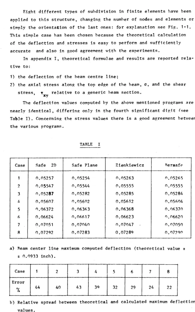
Eight different types of subdivision in finite elements have been applied to this structure, changing the number of nodes and elements or simply the orientation of the last ones: for explanation see Fig. 1-1. This simple case has been chosen because the theoretical calculation of the deflection and stresses is easy to perform and sufficiently accurate and also in good agreement with the experiments.
In appendix I, theoretical formulae and results are reported rela tive to:
1) the deflection of the beam centre line;
2) the axial stress along the top edge of the beam, σ, and the shear
stress, τ relative to a generic beam section, xy
The deflection values computed by the above mentioned programs are nearly identical, differing only in the fourth significant digit (see Table I). Concerning the stress values there is a good agreement between the various programs.
TABLE I Case
1
2
3
Λ5
67
R
Safe 2D Π.05257 0.05547 0.05287 0.05607 0.06372 0.06624 0.07051 0.07292 Safe Plane 0.05254 0.05544 0.05282 0.05602 0.06363 0.06617 0.07040 0.07283 Zienkiewicz 0.05263 0.05555 0.05285 0.05612 0.06368 0.06623 0.07047 0.07289 Bersafe 0.05265 Ο.Π5555 0.05284 0.05604 0.06370 Π.06620 0.07050 0.07290a) Beam center line maximum computed deflection (theoretical value s 0.0933 inch).
Case Error
7.
1
442
403
434
3Q5
326
297
248
22- 6
From these results it appears that, at least for small problems, the computed displacements are practically indipendent from the nume-rical method used to solve the resulting system of linear equations.
Furthermore it is clear that the difference, which exists hetween the programs which use a different numerical technique is of the same order of magnitude of the difference between programs using the same technique.
INFLUENCE OF THE ORIENTATION AND REFINEMENT OF THE MESH
The above calculated results are also used to study the influence of the mesh orientation and refinement on the convergence of the discrete model to the actual situation.
Fig. 1-2 represents the centre line deflections as obtained with the eight considered discretizations. Pith increasing number of nodes and elements, improved approximations are obtained, even if the deflection values still remain below of the theoretical one (dot and dash). In par-ticular, the two kinds of lines, dashed (cases 1-3-5-7) and continuous
(cases 2-4-6-8), refer to subdivisions with a different orientation of the elements: one can see that also this simple difference has an appre-ciable influence on the accuracy of the results.
For the eight different types of meshes considered a comparison has been also made, which regards the axial stress along the top edge of the beam (see Fig. 1-3). To do such a comparison the element stress values rather than the averaged nodal stress values have been considered because these values were directly available from Bersafe and Safe-2D programs only.
In Fig. 1-3 it is possible to see that a mesh refinement near the constrained face improves only the local stress values, but it does not transmit any influence towards the free end of the beam: or rather, while this mesh refinement improves the displacements along the whole beam, stresses are only locally affected.
7
number of points, the section X ■ 2 inch, in which the meshes are more
dense has been considered.
The behaviour is not very satisfactory and expecially the type
of element orientation which proved to be the most convenient for
displacements now appears unsatisfactory for shear stresses,
(see Fig. 14).
INFLUENCE OF THE TYPE OF ELEMENTS
The present study may be considered a supplement to the work reported
in RD/B/N1848 by K. Fullärd and T.K. Hellen /~F_7. It has been already
pointed out that not only the mesh refinement improves the results, but
also the choice of an appropriate type of element, which is able to describe
with sufficient accuracy the actual deformation field.
Fig. 15 illustrates this fact in a limit case. A discretization with
only two elements of the EP16 type (quadrilateral element with midside nodes)
gives a quite accurate beam center line deflection, even better than the one
obtained by using a subdivision with 46 elements of the EP6 type (simple
triangles).
This result may be generalized and one can say that the use of elements
with more complex shape functions (e.g. with midside nodes) produces
better results also in cases with a considerably lower number of nodes and
elements.
Referring to the subdivisions of the Fig. 16, one can see that regar
ding the displacements (see Fig. 15), the following two element patterns
are equivalent.
Concerning the axial stresses along
the top edge of the beam (Fig. 17),
those calculated by using quadrila
teral elements with midside nodes
are more accurate not withstanding
one has only half the number of ele
ments and one node less for each
quadrilateral element.
8
accurate near the constrained and the free beam faces than in the
central portion of the beam. To obtain accurate results also in these
two regions, it appears necessary to introduce a local mesh refinement.
A comparison based either on the deflection (Fig. 15) or on the
axial stresses (Fig. 18) has been also made between the following types
of elements:
1) EP6 (simple triangles)
2) FP8 (simple quadrilateral)
The adopted subdivisions are illustrated in Fig. 16 (cases 1011). In these conditions the beam center line deflection is far away from
the exact one although the deflection given by the FP8 elements is the
less accurate. Regarding the stresses, one can see (Fig. 18) that while
the FP8 elements give acceptable values, the EPfi elements give a consi
derable deviation which in some zones achieve the values of 40 or 50 %.
Using subdivisions with FP12 and EP16 elements (Fig. 16, cases 12
13) one obtains a very good approximation relative to beam deflection
(see Fig. 15).
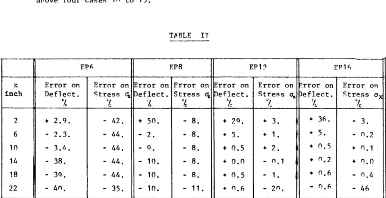
Tt is interesting to see how much are different the theoretical
and calculated values, when are comparated the displacements or the
stresses for the same type of element. This comparison is illustrated
in Table TT, for six different values of the X coordinate and for the
above four cases in to 13.
TABLE IT
X inch 2 6 10 14 18 22 EPfi Error on Deflect.
7.
♦ 2.9.
2.3.
3.Ä.
38. 39. 40. Error on Stress c¿ % 42. 44. 44. 44. 44. 35. EP8 Error on Deflect. 7c ♦ 50. 2. 9. 10. 10. 10. Error ( Stress 7c 8. 8. 8. 8. 8. 11 Dn • EP1? Error on Deflect. % ♦ 2<>. ♦ 5.
+ 0.5
♦ 0.0
·» 0.5
+ 0.6
Error Stress
X
♦ 3. ♦ 1. ♦ 2. n.1 1.
2o. an EP16 ?rror on Deflect.
X
♦ 36. ♦ 5.♦ 0.5
♦ 0.2
♦ 0.6
0.6
Error on Stress Ov
3.
0.2
♦ 0.1
♦ 0.0
0.4
46
9
It may be noted that deflections are in general determined with
a greater accuracy than stresses by the displacement formulation of
the finite element method.
For a more detailed analysis of the performances of the different
element types, the following discretizations involving further mesh
refinements were studied:
1) EP6; 86Λ Elements, 481 nodes (case 14)
2) EP8: 432 Elements, 481 nodes (case 15)
3) FP16;432 Elements,13^3 nodes (case 16)
The diagram in Fig. 19 relative to the sections X = 2 inch and
X ■ 12 inch, shows the axial stresses as a function of the Y coordinate.
The calculate results are very closed to the theoretical ones, in the
EP16 case they are even coincident.
The only zone in which there is some deviation is the one near the
top and bottom edges of the beam. For better understanding this fact let us
consider the diagram in Fig. 110. This diagram reproduces the σ max
behaviour along the whole beam for cases 14 and 15 (EP6 and F.P8 elments) .
Here the triangular and quadrilateral elements are compared taking the
stresses values in each element before any averaging procedure.
One can see from the diagram, that the values relative to the section
X = 12 inch are better than those of the section X s 2 inch.
This is due to the fact that such a section is near the constrained
face of the beam and that it is affected by the approximative representation
of the boundary conditions. Indeed such a deviation takes place also for
the sections between X ■ 0 and X s 2,5 inches.
Concerning the case 16 there is an excellent agreement between theore
tical and calculated values along the whole beam (Fig. 111). Also the
discontinuity of the stress between adjacent elements is reduced to small
values and goes to zero for X ■ à inch.
The above examples show, that with the exception of the zones near the
faces of the beam, very satisfactory results may be obtained also with a
limited mesh refinement or simply by using higher order elements.
Shear stresses have been analysed for the three types of subdivisions
already mentioned, i.e. EP6, EP8, EP16. Only these cases have a sufficient
number of points to describe a reasonable detailed behaviour of the shear
10
One can see in Fig. 112, that at least for the section X « 12 inch,
a good approximation, which in the EP1fi case is a perfect coincidence, may be
obtained. Besides the FPfi discretization gives better results than the FP8
case, except for the zones near the center line and the edges of the beam.
Indeed it must be noted that the shear stress does not remain strictly
constant in every section as anticipated by the beam theory.
This is caused by the imperfect simulation of both the constraints
and the loads.
The shear stress becomes constant at a distance from the constrained
face equal to the half height of the beam in the EP8 case and to a quater
in the F.Pfi case. Near the loaded face of the beam the distance becomes
about the half of the previous values.
Regarding the influence of the mesh orientation on the results it is
possible to observe (see Fig. 112) that a triangular mesh of the herring
bone kind, orientated like in case 1; presents some points which do not
respect the theoretical behaviour. More precisely, the shear stress curve
shows a depression on the beam center line, while, near the edges of the
beam, it mantains values far from zero.
On the contrary if one uses a mesh like in case 2 (i.e. orientated in
the opposite sense): the maximum value is overextimated and the shear stress
on the edge of the beam reaches a value which is less than half the one of
the previous case.
On the other hand, one must
consider that the first type
of mesh gives more satisfactory
deflection values than the
second type.
For better understanding the
behaviour of the shear stress
in the neighbourhood of the
constrained section one may observe the diagram in Fig. 113, related to cases
1415.
One can see that in the constrained section the quadrilateral elements
give values deviating from the theoretical ones. For X r 2 inch the curve
begins to approximate considerably the theoretical shape. The triangular
elements are less disturbed by the boundary, and for X ■ 2 inch the shear
11
stress behaviour is realy satisfactory and is very close to the theoretical
one.
In Fig. 14 the τ distribution, calculated with the discretization
xy
of case 16, is shown for different sections along the beam axis.
For the constrained section, X : 0 inch the curve has the less satis
factory behaviour but on the section at X : 2 inch, the behaviour begins
to be good. From X ■ 4 inch to X s 6 inch the τ curve arrives to a defini
xy
tive shape, which is maintained almost till the loaded section. For
X ■ 22 inch the deviation starts to become significant, and for the loaded
section X r 24 inch there are some little obscillations around the exact
value.
CONSIDERATION ON THE REQUIRED COMPUTER TIME
The computer used for the above described calculations was an IRM
360/65 and all the values of time referred in this paragraph are relative
to this machine.
Following the analysis on the reliability of the finite element approach
we proceeded to examine the computer time necessary for the solution of the
previously considered problems.
The Zienkiewicz program for a single run spent 17 seconds, the Safe
Plane program about 28 seconds and the Bereafe and the Safe2D programs
both 31 seconds.
One can conclude that the Zienkiewicz program is the faster one, hut
the other three are equivalent also with respect to computer time.
These four programs have very different capabilities concerning the
type and size of thé problems they can solve.
The limits with respect to the size of the problem are on the total
number of nodes and elements. The Safe2D and the Zienkiewicz programs
have also limits on the number of elements for each partition and Bersafe
has a limit on the matrix bandwidth. All the four programs can solve two
dimensional cases with simple triangular elements. The Bersafe program can
solve two and threedimensional problems with various types of elements.
146 K RYTES
208 K BYTES
324 F RYTES
352 K RYTES
12
for the Zienkiewicz
for the SafePlane
for the Safe20
for the Rersafe
Running by the last program the four cases 10 to 13 of the Fig. 16,
needed the following execution times:
Case
10
11
12
13
Element tvpe
EPfi
EP8
EP1?
EP16
Number of elements
24
12
2¿
12
Number of nodes
21
21
65
63
Total time
34 sec
33 sec
47 sec
43 sec
Time to calculate stiffnes matrix and to solve the
system
4 sec
5 sec
11 sec
0 sec
*rom this series of data we may conclude that the increase of the
execution time Is more a consequence of the number of nodes than of the
use of higher order elements.
For better seeing the influence of these two different factors, it
is useful to consider the three cases above analvsed:
Case
14
15
16
Element type
EPfi
EP8
EP16
Number of elements
86Δ
432
432
Number of nodes
481
481
1393
Calculation time
(min)
4.36
3.27
24.15
Total time (min)
11.31
7.04
34.47
From these values and considering also the numerical results, one can
see that the EP8 element is the more convenient to solve plane problems.
It gives fairly good values and the results which can be obtained by using
the EP16 element does not justify the involved increase of execution time.
- 13
A P P E N D I X I
For the theoretical calculation of the deflection relative to the centre line of a cantilever beam and of the axial and tangential stresses we have used the formula of the beam theory valid in the elastic field. The deflection equation is the following:
f : 1 ( Ρ χ3
2_ 3 PI χ PI , E I
S (1-x) GA
where the first term between square brackets accounts for bending only, while the other one considers the shearing stresses. The orientation of the X axis must be taken like in Fig. 1, with the origin at the free end.The notations which
appear in the equation have the following signification and value.
fi -'
Young's modulus; E ; 10 lb in ^. Concentrated load: Ρ : 8on lb Beam lenght; 1 = 24 in
Momentum of Inertia; I : 42,66 in F
Shear modulus; G
2(1*v) Poisson's modulus: ν ; 0.2
Shear factor; β = - s 1,2
Cross-sectional area; A ; 8 in^
The calculated values are the following, (x = 1 - X):
O.0304in
fx=o = O.ooOOin
f 0 r 0.0014in
X"2
f . 0.0044in xs4 "
f , s 0.0081 in X"6
f 0 s 0.0148in
Xso
x=12
x=16 0.0494in
fx-20 = n-0 7 0 7 i n
f _. r 0.0933in x=24
We did the same for the calculation of σ
4 P.b
max (1 - x)
max
b = 1 inch
14
The applied notation have the same signification and the same values
of those used in the previous calculation. The obtained results are the
following:
σ = 18on lb/in2 σ Λ. ζ 750 lb/in2
x«o χ·14
σ _ » 1650 lb/in2 σ Λ, ζ 600 lb/in2
χ:2 χ=16
σ . 15Ο0 lb/1n2 σ . 450 lb/in2
x;4 χ«18
σ , =1350 lb/In2 σ _Λ r 300 lb/in2
χ:0 χ»20
σ _ . 1200 ]b/ln2 σ ._ = 150 lb/in2
χ«8 χ=22
σ Λη m loso lb/in2 σ „, = 0 lb/in2
XrlO χ=24
σ ,„ οοη lb/in2
Χ1? a
One can see clearly that the behaviour is linear with the maximum
value in the constrained section which decrease with decreasing abscissa
and becomes zero for X = 0 inch.
We calculated the tangential stresses also with the beam theory.
They stay constant for each section of the beam, which means it is inde
pendent from the fixed section distance. Tt has a parabolic behaviour
with respect to the beam height. The used formula for this theoretical
calculation is:
p ru2 , 2Y
τ = (h 4 ν )
x v 8 τ
One can see immediately that it is zero on the outline, indeed
h : 2v. The found values are:
Ty=1.75 "
Ty.1.50 " 1 2 8· '9 0 l b l n"2
Vl.25
s 1 3 5·
3 5 lb ln"
2Vi.no '
u° ·
6 2 l b in"
2Ty = 0 . 7 5 = m · 7 2 l b i n"2
Tv = o . 5 0 = U 7 · 6 5 l b l n"2
Ty = 0 . 2 5 a 1 4 P· *1 l b i n"2
Ty - O . 0 0 " 1 5 0 . 2 5 l b i n "2
γ · 4 . 0 0
Ty = 3 . 7 5
Ty = 3 . 5 0
Tv . 3 . 2 5
Ty s 3 . o n
Ty = 2 . 7 5
Ty = 2 . 5 o
Ty - 2 . 2 5
T
y 2 . o o
a
. ζ
■ = M Ζ = = =
0 . 0 0
1 8 . 1 6
3 5 . 1 5
5 0 . 9 7
6 5 . 6 2
7 0 . 1 0
0 1 . 4 "
1 0 2 . 5 2
112.5·" l b l b l b l b l b l b l b
: i t
ι l b
- 7
i n ·'
- 7
i n -7 i n
-i n "2
i n "2
- 7
i n
-i n "2
, i n "2
15
-CONCLUDTNC REMARKS,
The analysis performed on the accuracy of the computer programs based on the finite element method allows the following remarks:
A) The considered computer programs are equivalent in the limit of the ''engineering accuracy''.
B) All the programs converge to the ''exact'' solution when the number of finite elements used in the discrete models is increased.
C) However a satisfactory and cheaper (with respect to the computer time) solution may be obtained by the choice of elements of a suitable type.
ACKNOWLEDGMENTS
16
RFFFPENCES
/~A_? D.C. CORNELL, Y.R. PASHTD " A Computer Program for the Stress
Analysis and Design of Twodimensional Composite podies''
Report GA 7851 June 30, 1967.
/"R_7 D.C. CORNELL, V.R. RASHID " A Computer Program for the Stress
Analysis of Plane and Axisymmetric Composite Structures''
Report 0Λ "07fi February 12, 1969.
¿~C.J O.C. ZIENKIEWICZ "The Finite element Metbod in Structural
and Continuum Mechanics'' London, Mc CrowHill 10fi7.
/"D_/ T.K. HELLEN " A Frontsolution for Finite Element Techniques"
CFC3 internal report.
/ Vj T.K. HELLEM "Bersafe (pha<;e 1), A Computer System for Stress
Analysis" Part. 1, Report RD/R/N17fi1.
I_~TJ K. FULLÄRD and T.V. UELLEN "An Investigation of the ^ccuracv
of Plane Finite Elements in the Cantilever Ream Program''
|case1
19 NODES
22ELEMENTS
case 2
case3
21 NODES
2AELEMENTS
c as e A
case 5
28 NODES
34 ELEMENTS
case6
case7
35 NODES
Z.6ELEMENTS
case8
I
I -1
-o
2 AÓ
4. IO"
5.10"
Í6A0
iUO1
HG..1-3
iOJ.0
-i
--1 - 3 =4 =5 - 6
U3 I
.= 1
.= 2
= 5 .= 6
. = 7
. = 8
X=2
O
¡9x
IAO'
ivf
-—*—-.
TK-,
Jf-^
iO iZ ¿4 16 18 SO et
z*\
x-Êpi6;EPiï (ea.sc iT>-iZ)
o*Bpi6(2EL£ñ. ( e a s e - 9 )
[¿i UO Dl
+ --EP6 'ea.se io)
Z.iO
4.1CT
-2.
5 Ad -t
hr
x a s e 9
v
\\ \
^
\ N
\
• = EP8 ( e a. s e il)
!
ro
640"
fio-
8.10-9. JO"
FIG 1-5
\ N
N
\ \
\ \
\ \
\ \
EP. 6 caseio
21 NODES
2k
ELEMENTS
10 13 li
ii Í4
12 15
it
n
EP. 8 case11
21 NODES
12 ELEMENTS
Í 9
20
li
ii lé 21 26 31 36 41 46 51 56 61 1 6 9 14 Í? 22 25 30 33 38 41 46 -49
5 0
h
r
Ρ
fa ζ 3 4 5 7 8 io ii 12 13 15 16 18 19 20 21 23 24 26 2/ 28 25 31 32 34 35 36 3? 39 4 0 42 43 4 4 45 4¡f *8EP.12 case12
65NODES
24ELEMENTS
EP.16 case13
53 NODES
12 ELEMENTS
FIG1-6
51
52
it.iO
16.10
14. tO
mo
ito-SAO1
Ο,ΑΟ1
4.iOJ
i.\0' 6*
^ ,
\
.EP16 ( t a . s e 43)
tPi% ( e a . s e il) s>.
Os
^ < ^
te
FIG 1-7
" " ^ ^ S . ^ s .
^ ^
^ ^
i - S 1
X--12
FIG 1-9
EP fe (case, i A) . EP 8 (ease, i S]
+ E P i é ( c a . s e 16)
K)
. EP 6
(ense IA)
...
EP 8 ( e a s e
45)
ÍIUO*
iUc
1UJO1
ilio*
iO.iO1
ÎJO1
6. IO1
4.
io'
2.10*
FIG 1-11
ΕΡ16 ( c a . s e
Í6)
AO EP 6 (c a . 5 « 44)
. E P 8 ( d i s e iS)
+ EP16 ( c 5LS e 16)
FIG1-12
ro
_ t h e o r e t i c a l
__EP8 (ea.se
i 5)
.._EP6 (ease 14-)
i ; X = 2 2;X=0 3;X ^ 2
A;X=0
FIG1-13
ΓΟ 'X)
EP16
(ca.seî6)
_ _ X = 2
X= 4
X= 6
X = 2 2
X = 2 4
C
FIG1-U
All scientific and technical reports published b y the Commission of
'f
specimen copies please write t o : All sc«Is
b
E
"euro [''IPL
European Communities are announced in the monthly periodical
abstracts". For subscription (1 year: B.Fr. 1025—) or free
„
and-Duchy of Luxembourg)
iïww
;l*L'tøTu ι-ί·ΕΜ ï ¡ ιill
η««' ffiiijiiSfelli raup«
hw~ 'MLΤ·.,,.·ΪΪΙ! -fir$>
L « * W
pit «,
κ
».ani
■
i
mimé
"
:
ÉlIÉ
•'li1'«
i«
! To disseminate knowledge is to disseminate prosperity — I mean
; general prosperity and not individual riches — and with prosperity
| disappears the greater part of the evil which is our heritage from
! darker times
t\M
,
r
ipil I .„.,
#ÍIÍÍI!ililflll
Alfred Nobel
mmmwm
SI
i f f j ^ H * I
«pip
w
:?
'ift
'Jfcr-SALES OFFICES
■I'M';
111
The Office f o r Official Publications sells all documents published by t h e Commission o f the European Communities at t h e addresses listed below, at t h e price given on cover.
UNITED STATES OF AMERICA
European Community Information 2100 M Street, N.W.
Suite 707
Washington, D.C. 20 037
Agencies 4}|£Η
00187 Roma —Via del Tritone 61/A e 61/Β
00187 Roma —Via XX Settembre (Palazzo
Ministero delle finanze) "allena Vittorio Emanuele 3
a Chiaia 5 - V i a Cavour 46/R
Via XII Ottobre 172 40125 Bologna — Strada Maggiore 23/A
BELGIUM
Moniteur belge — Belgisch Staatsblad Rue de Louvain 40-42 — Leuvenseweg 40-42 1000 Bruxelles — 1000 Brussal — Tel. 12 00 2.6 CCP 50-80 — Postgiro 50-80
Agency:
Librairie européenne — Europese Boekhandel Rue de la Loi 244 — Wetstraat 244
m
1040 Bruxelles — 1040 BrusselGRAND DUCHY OF LUXEMBOURG
Office for officiai publications of the European Communities Case postale 1003 — Luxembourg 1 and 29, rue Aldringen, Library Tel. 4 79 41 —CCP 191-90
Compte courant bancaire: BIL 8-109/6003/200 ,nde,
mm
NETHERLANDS
Staatsdrukkerij- en uitgeverijbedrijf Christoffel Plantijnstraat
's-Gravenhage — Tel. (070) 81 45 11 Giro 425 300
IRELAND
"m
JSNÌICS;Stationery Office Beggar's Bush Dublin 4
SWITZERLAN
Librairie Payot 6, rue Grenus
1211 Genève
CCP 12-236 Genève
D ÍS|||Í
■Wammm
mm
SWEDEN
FRANCE
Siili«
¡IMS»«!!·* ■tfPtM+.-yffln
Service de vente en
des Communautés européennes 26, rue Desaix
75 Paris-15· —Tel. (1) 306.5100 CCP Paris 23-96
Wmm
GERMANY (FR)Librairie CE. Fritze 2, Fredsgatan Stockholm 16 Post Giro
SPAIN
Libreria Mundi
Verlag Bundesanzeiger 5 Köln 1 — Postfach 108 006 Tel. (0221) 21 03 48
Telex; Anzeiger Bonn 08 882 595 Postschockkonto 834 00 Köln
¡ ü Elia
Mi
OTHER COUNTRIES
Sales Office for official publications of the European Communities Case postale 1003 — Luxembourg 1 Tel. 4 79 41 —CCP 191-90
Compte courant bancaire: BIL 8-109/6003/200
. J M !
uta
OFFICE FOR OFFICIAL PUBLICATIONS OF THE EUROPEAN COMMUNITIES Case postale 1003 — Luxembourg 1