CORRECTION BIAS ERROR TOOTH FLANK OF A HELICAL GEAR
GENERATED BY CNC GEAR SHAVING MACHINE
Van-The Tran
Department of Mechanical Engineering, Hung Yen University of Technology and Education, Hung Yen City, Vietnam E-Mail: [email protected]
ABSTRACT
On CNC shaving machine, the tooth flank of work gear can be crowned longitudinally by varying the plunge motion of shaving cutter. However, which will induce a bias error on tooth flank of the shaved work gear. In this paper, therefore, we propose a new CNC shaving method by modifying work gear rotation angle and without varying the plunge motion of shaving cutter during the gear shaving process that can be reduced the bias error of the tooth flank on shaved work gear. A numeral example is presented to illustrate and verified the merits of the proposed CNC gear shaving method in longitudinal crowning to obtain the tooth flank of work gear surface without bias error.
Keywords: CNC gear shaving, longitudinal crowning, bias error tooth flank.
INTRODUCTION
The finish process for generation of involute helical gear is usually performed by gear shaving machine. Wherein, two helical gears are meshed with together in crossed axes. One gear of the gear pair is shaving cutter with gashed teeth to obtain cutting edges. These cutting edges act as blades and cut very thin pieces material of teeth of work gear. In this process, the longitudinal crowning of work gear surface can be achieved by plunging motion. However, which will induce twisted tooth flanks on the shaved work gear. Therefore, we propose a methodology for longitudinal crowning by modification of work gear rotation angle and without variation of the plunge during the gear shaving process.
Basic mesh conditions for the involute helical gear set have been presented in some textbooks [1, 2]. In 1990, Endoy [3] and Dugas [4] have shown some important discussions of the shaving process, such as the approximate life cycle time and the even contact. A stochastic model to predict the effect of shaving cutter performance on the finished tooth form was proposed by Moriwaki [5] and Moriwaki and Fujita [6]. In 1996, a MS-Windows application program has been developed to design the specification of the shaving cutter from the given shaved gear by Kim and Kim [7].Tooth profile errors of the plunge shaving cutter due to errors from the setup of grinding machines were explored by Koga et al.
[8]. And Miao and Koga [9] have developed a mathematical model of a theoretical tooth profile for the plunge shaving cutter. Subsequently, Seol and Litvin [10] proposed a modification of geometry of involute spur and helical gears with parallel and crossed axes on gear shaving for localization and stabilization of bearing contact and reduction of noise and vibration. More recently, a numerical method to simulate the auxiliary crowning in the parallel gear shaving process has developed by Hsu [11]. Chang et al. [12] and Hung et al.
[13] developed a mathematical model of the shaved gear with auxiliary crowning taking into account the setting parameters of the gear shaving machine and cutter assembly errors. This model is considered at standard pitch cylinder. However, the meshing point between work gear and shaving cutter should be considered at operating pitch cylinder. Therefore, a mathematical model considering at operating pitch cylinder for the tooth profile of work gear finished by the parallel shaving process with the auxiliary crowning mechanism is proposed by Hsu and Fong [14]. Litvin et al. [15, 16] proposed and developed a method for a new topology of modified helical gear tooth surfaces that localization of the bearing contact under misalignment conditions based on meshing of a double-crowned gear with a standard helical involute gear. Finally, Hsu and Su [17] investigated the topologies, contact ellipses and transmission errors of the double-crowned work gear pairs generation by modified hob in gear-hobbing process. Recently,Tran et al. [18]proposed a novel hobbing method to generate anti-twist tooth flanks of the involute helical gear in longitudinal tooth crowning by supplementing an additional rotation angle of work gear during its hobbing process.
In this paper, to reduce the bias error of tooth flank on the helical gear surface, a new method for longitudinal crowning by modification of work gear rotation angle and without variation of the plunge motion during the gear shaving process is proposed. A numeral example is presented to illustrate and verify the merits of the proposed gear shaving method in longitudinal tooth crowning of helical gears.
MATHEMATICAL MODEL OF THE STANDARD SHAVING CUTTERS
unit normal vector of the standard shaving cutter’s right-hand side profile can be expressed in coordinate system
( , ) i i i
S x y as follows:
( ) [ ( ), ( )] ,T i u x ui y ui
r (1)
and ni( )u [nxi( ),u nyi( )] ,u T (2)
where
cos( ) sin( ),
i bs s s
x r u u u (3)
sin( ) cos( ),
i bs s s
y r u u u (4)
sin( ),
xi s
n u (5)
cos( s),
yi u
n (6)
and (2 ) ,
2 pts
s pts
s ps
s inv
N r
(7)
where u is the involute profile parameter, rbs is the radius of the base cylinder of shaving cutter, spts is the cross
section space width on the pitch cylinder of shaving cutter,
s
N is the number of teeth of the shaving cutter, rps is the
shaving cutter pitch radius, and pts is the profile angle in transverse section, as shown in Figure-1(a).
By transforming coordinate system of the helical motion from Si to Ss, as shown in Figure-1(b), the position vector and unit normal vector of the standard shaving cutter’s surface can be expressed in coordinate system S x y zs( s, s, s) as follows:
cos sin 0 0
( , ) ( )
sin cos 0 0
( , ) ( )
( , ) ,
0 0 1
( , ) 0
1 0 0 0 1 1
s i
s i
s
ps s
x u x u
y u y u
u
t z u
r (8)
( , ) cos sin 0 ( )
( , ) ( , ) sin cos 0 ( ) ,
0 0 1
( , ) 1
s i
s i
s
x x
s y y
z
n u n u
u n u n u
n u
n (9)
where is the longitudinal parameter, tps rpscosps is the helix parameter, ps is the pitch helix angle of the shaving cutter surface.
i
x
i
y
,
i s
z
s
y
r
x
i
O
r
O
ps
t
pts
s
u i
n
1
( )
iu r
ps
r
bs
r i
y
i
x
i
O
M
( )a ( )b
pts
s
Figure-1. Generation process of the standard shaving cutter surface.
MATHEMATICAL MODEL OF THE CROWNED WORK GEAR
The coordinate systems for the shaving process of helical gears with longitudinal crowning teeth are shown in Figure-2, where coordinate systems S x y zs( s, s, s) and
1( ,1 1, 1)
S x y z are rigidly connected to the shaving cutter and work gear, respectively, while the coordinate system
( , , )
b b b b
S x y z is rigidly connected to the frame of shaving
machine, and S x y zc( c, c, c), Sd(xd,yd,zd), ( , , )
e e e e
shaving cutter and work gear. The crossed angle s of the shaving cutter and work gear axes is usually a machine-tool setting. For conventional longitudinal tooth crowing of a work gear, it is accomplished by modifying the radial feed-in Eos( )l to a second order polynomial, such as
( )l ( 0 ) 2 os os
E E al , as shown in Fig. 2. However, this modification causes a bias error of the tooth flank on the helical gear. Therefore, this study proposes a novel shaving method to reduce bias error of tooth flanks on the crowned helical gear. The rotating angle of work gear,
1( s, )l
, is set as a function of shaving cutter’s rotation
angle, s, and the amount of shaving cutter’s traverse feed, l.
The position vector rs( , )u (see Eq. (8)) and unit normal ( , )ns u (see Eq. (9)) present locus of shaving cutter surface, respectively. By applying the homogeneous coordinate transformation matrix equation from Ss to S1,
the locus of shaving cutter can be represented in coordinate system S1 as follows:
1( , ,u s, )l 1s( , )s l s( , ),u
r M r (10)
where
( )
1 1 1 1 1 1
( )
1 1 1 1 1 1
1
cos sin sin cos cos cos cos sin sin cos sin sin cos
cos sin cos cos sin sin sin cos cos cos sin cos sin
( , )
sin sin sin cos cos
0 0 0 1
l
s s s s s s s os
l
s s s s s s s os
s s
s s s s s
E
E l
l
M
.
(11)
1
s
(0)
os
E
,
c b
x
s
y
b
y
,
b s
z
c
z
e
y
d
y z1,g
g
y
,
g f
x
1
x
1
y
d
x
s
x
s
, ,
f e d
z
f
y
e
x
c
y
2
.
a l
l
, ,
c b s
O
1,g
O
f
O
,
e d
O
( )l os
E
Figure-2. Coordinate systems for the CNC shaving machine.
After some mathematical operations, the locus of shaving cutter surface can be simplified as follows:
1( , , , ) [ ( , ,1 , ), 1( , , , ), 1( , , , ),1] ,
T
s s s s
u l x u l y u l z u l
r (12)
where
( )
1 cos 1( osl scos s ssin s) sin 1[ ssin s cos s( scos s ssin s)],
x E x y z y x (13)
( )
1 cos 1[ ssin s cos ( scos s ssin s)] sin 1( osl scos s ssin s),
and z1 l zscoss(yscossxssins) sins. (15)
There are two independent kinematic parameters l and s in the CNC shaving process. Therefore, there
are two equations of meshing between the work gear and the shaving cutter as follows:
1 2 2
1 1 1
( , , , ), ( , , , ), ( , , , )
( , , s, ) s s s 0,
s
x u l y u l z u l
f u l
n (16)
and
1 1 1
2 1
( , , , ), ( , , , ), ( , , , )
( , , s, ) x u sl y u sl z u s l 0,
f u l
l
n (17)
where
1( , , , ) 1 ( , ) s( , ), s( , ), s( , ) ,
T
s s s x y z
u l l n u n u n u
n L (18)
The transformation matrix L1s(s, )l is the sub-matrix of M1s by deleting the last column and row.
The rotational relationship between the work gear and shaving cutter is defined as
1 1 1 1 tan s o s o N l N r
(19)
where symbols Ns and N1 indicate the number of teeth
of the shaving cutter and gear, respectively. Because the work gear rotation angle 1( s, )l is a linear function of the shaving cutter’s rotation angle s and the traverse movement of work gear l along the axis of shaving cutter, it can be approximated in terms of the rotating angle s and traverse movement l by nth-order Taylor polynomials, expanded at an arbitrary point
0 0
( , )s l (s , )l , as a function dependent on two variables. The rotational relation among the work gear, shaving cutter, and the Taylor series can then be expressed by
1( , ) 1( , ) 2( , ) ( , ) ( , ),
n
s l F s l F s l Fn s l R s l
(20)
where
1 1 0 0 1 0 0 1 0 0
1
1 0 0
1 1
( , ) ( , ) ( ) ( , ) ( ) ( , )
tan
( , ),
s
s s s s l s
s o
s s
o
F l l l l l
N l l N r
(21)
2 2
2 0 1 0 0 0 0 1 0 0 0 1 0 0
1
( , ) ( ) ( ) ( , ) 2 ( ) ( ) (( ) ) ( , ) ( ) ( ) ( , ) ,
2! s s
s s s s s s l s l s
F l l l l l l l l (22)
1
( ) 1 ( 1)
0 1 0 0 0 0 1 0 0
( 1) ( )
1
0 0 1 0 0 0 1 0 0
1 ( , ) ( ) ( ) ( , ) .( ) ( ) (( ) ) ( , ) ! .( )( ) (( ) ) ( , ) ( ) ( ) ( , ) , s s n n n n
n s s s s s s l s
n n
n n
s s l s l s
F l l n l l l
n
n l l l l l l
(23)
andRn(s, )l is the remainder of the Taylor series, which can be omitted for simplicity. By substituting Eqs. (21)– (23) into Eq. (20) and performing certain mathematical operations, we can then represent Eq. (20) in second-order Taylor polynomials as follows:
2 2
1
1 0 1 2 3 4 5
1 1
tan
( , ) s o ,
s s s s s
o
N
l l a a a l a a l a l
N r
(24)
where
a
0, ...,
a
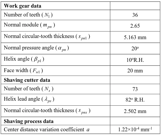
5are coefficients of the proposed modified rotation angle for the helical work gear. These coefficients can be obtained directly from Eq. (20) by solving their respective derivatives. The generated tooth surface depends on the motion functions of the rotating angle s and the traverse movement l. The coefficients of Eq. (24)can then be used in the gear shaving process to generate a crowned helical gear with bias error of the tooth flanks. The tooth surface of shaved work gear can be defined by solving Equations (10), (16) and (17), simultaneously.
modification coefficient are given in Table-1. The shaving machine setup data are calculated according to the basic
[image:5.612.169.443.143.374.2]meshing conditions as illustrated in Ref. [1, 2].
Table-1. Basic data of the gear and shaving cutter.
Work gear data
Number of teeth (N1) 36
Normal module (mpn) 2.65
Normal circular-tooth thickness (spn1) 5.163 mm
Normal pressure angle (pn) 20o
Helix angle (p1) 10oR.H.
Face width (Fw1) 20 mm
Shaving cutter data
Number of teeth (Ns) 73
Helix lead angle (ps) 82o R.H.
Normal circular-tooth thickness (spns) 2.502 mm
Shaving process data
Center distance variation coefficient a 1.22×10⁻⁴ mm-1
According to the algorithm presented in Ref. [18], the modifying work gear rotation angle, expressed in
Eq. (24), for the helical gear with longitudinal tooth crowning is determined as follows:
5 5 5 2 5 7 2
1
73
( , ) 364.042 10 5.349 10 126.1 10 2.066 10 6.917 10 ,
36
s l s l s s sl l
(25)
The normal deviations and simulated tooth surface topographies of the crowned helical gear, with and without modifying work gear rotation angle for the shaved work gear, are shown in Tables 2-3 and Figures 3-4, respectively. The maximum bias error of tooth flank is about 3.39mfor the generated work gear tooth flank by applying conventional shaving method. And after modifying work gear rotation angle in gear shaving process, the maximum bias error of tooth flank is reduced from 3, 39m to a negligible amount of 0.11m. It is
verified that the bias error of the tooth flank is reduced significantly by modifying work gear rotation angle proposed in this study. The longitudinal crowning evenness ratio for the tooth flank surface, as shown in Table 2 and Fig. 3 (Rce0.59), is much smaller than that of the tooth flank surface, generated by modifying work gear rotation angle, as shown in Table-3 and Figure-4
0.98)
(Rce .
Table-2. Normal deviations of crowned work gear surfaces generated with original formula.
Top Land (Unit:m)
E -5.0 -2.6 -1.0 -0.1 -0.1 -0.9 -2.5 -5.0 -8.4
D -5.5 -3.0 -1.2 -0.2 0.0 -0.6 -2.1 -4.5 -7.7
C -6.2 -3.5 -1.5 -0.4 0.0 -0.4 -1.7 -3.9 -6.9
B -6.9 -4.1 -1.9 -0.6 0.0 -0.3 -1.3 -3.3 -6.1
A -8.1 -5.0 -2.6 -1.0 -0.2 -0.1 -0.9 -2.6 -5.1
[image:5.612.89.517.598.715.2]maximum tooth flank twist = 3.39m and longitudinal crowning evenness ratioRce 0.59
Table-3. Normal deviations of crowned work gear surfaces generated with modifying work gear rotation angle.
Top Land (Unit:m)
E -7.0 -4.1 -2.1 -0.9 -0.4 -0.9 -2.1 -4.1 -7.0
D -6.8 -3.9 -1.8 -0.6 -0.2 -0.6 -1.8 -3.9 -6.7
C -6.6 -3.7 -1.7 -0.4 0.0 -0.4 -1.7 -3.7 -6.6
B -6.6 -3.7 -1.6 -0.4 0.0 -0.4 -1.6 -3.7 -6.5
A -6.9 -4.0 -1.9 -0.7 -0.2 -0.7 -1.9 -3.9 -6.8
1 2 3 4 5 6 7 8 9 Gear Root
maximum tooth flank twist = 0.11m and longitudinal crowning evenness ratio Rce0.98
Figure-3. Simulated topography of crowned work gear surfaces generated with original formula.
Figure-4. Simulated topography of crowned work gear surfaces generated with modifying work gear
rotation angle.
CONCLUSIONS
This paper proposes a new CNC shaving method for longitudinal crowning tooth flank by modifying the work gear rotation angle and without varying the center distance during the gear shaving process. The tooth surface topographies of the conventional and proposed shaved helical gear are simulated and compared. It reveals
that the bias error of tooth flank on helical gear is really significantly reduced by applying our proposed shaving method.
Nomenclature
jki
s circular tooth thickness, j = b, o, p; k = t, n; i = 1, 2
jki
helix angle, j = b, o, p; k = t, n; i = 1, 2 crossed angle
jki
lead angle, j = b, o, p; k = t, n; i = 1, 2
jki
m module, j = b, o, p; k = t, n; i = 1, 2
on
p normal circular pitch measured at the operating pitch plane
i
N number of teeth, i = 1, 2
os
E operating distance
jki
pressure angle, j = b, o, p; k = t, n; i = 1, 2
jki
r radius of the pitch circle, j = b, o, p; k = t, n; i = 1, 2
a center distance variation coefficient Subscripts
b base circle
n measured in normal section
t measured in transverse section
o operating pitch circle
p pitch circle
s shaving
1 work gear
REFERENCES
unit: m
-8.1 -5.1
C -6.9
E -8.4
-6.2
-5.0
1 2 3 4 5 6 7 8 A,9
B
D
Top land
Gear root
-6.9 -6.8
C, -6.6
E, -7.0
-6.6 B
D
-7.0 Top land
1 2 3 4 5 6 7 8 A,9
[1] F.L. Litvin. 1989. Theory of Gearing, NASA RP-1212 (AVSCOM 88-C-C035), Washington, DC., USA.
[2] F.L. Litvin. 1994. Gear Geometry and Applied Theory, PTR Prentice Hall, Englewood Cliffs, NJ. pp. 412-468.
[3] R. Endoy, Gear Hobbing. 1990. Shaping and Shaving: A Guide to Cycle Time Estimation and Process Planning, Society of Manufacturing Engineers, Dearborn, MI. pp. 63-74.
[4] J.P. Dugas. 1990. Gear Design Manufacturing and Inspection Manual, Society of Automotive Engineers, Warrendale, PA. pp. 327-334.
[5] I. Moriwaki. 1993. Numerical Analysis of Tooth Forms of Shaved Gears. Transactions of the Japan Society of Mechanical Engineers. 59(568): 3895-3901.
[6] I. Moriwaki, M. Fujita. 1994. Effect of Cutter Performance on Finished Tooth Form in Gear Shaving. Journal of Mechanical Design. 116(3): 701-705.
[7] J.D. Kim, D.S. Kim. 1996. The Development of Software for Shaving Cutter Design. Journal of Materials Processing Technology. 59: 359-366.
[8] H. Koga, K. Umezawa, H.C. Miao. 1996. Analysis of Plunge Shaving Process for Helical Gears with Tooth Modifications. ASME, Power Transmission and Gearing Conference, San Diego, CA. 88, pp. 265-273.
[9] H.C. Miao, H. Koga. 1996. Design and Analysis of Plunge Shaving for Finishing Gears with Tooth Profile Modifications. ASME, Power Transmission and Gearing Conference, San Diego, CA. 88, pp. 275-281.
[10]I.H. Seol, F.L. Litvin. 2001. Computerized Generation and Simulation of Meshing of Modified Spur and Helical Gears Manufactured by Shaving, Computer Methods in Applied Mechanics and Engineering. 190, pp. 5037-5055.
[11]R.H. Hsu. 2006. Theoretical and Practical Investigations on the Design of Plunge Shaving Cutter. Doctoral Dissertation of National Chung Cheng University, Taiwan. pp. 80-103.
[12]C.H. Hung, J.H. Liu, S.L. Chang, H.J. Lin. 2007. Simulation of Gear Shaving with Considerations on Cutter Assembly Errors and Machine Setting Parameters, Journal of Advanced Manufacturing 35(3-4): 400-407.
[13]S.L. Chang, H.J. Lin, C.H. Chu, J.H. Liu, C.H. Hung. 2007. Simulation of Gear Shaving Machine and Tooth Contact Analysis of the Shaved Gears. The IAENG International Conference on Industrial Engineering, Hong Kong. pp. 2187-2192.
[14]R.H. Hsu, Z.H. Fong. 2010. Analysis of Auxiliary Crowning in Parallel Gear Shaving. Mechanism and Machine Theory. 45, pp. 1298-1313.
[15]F.L. Litvin, A. Fuentes, I.G. Peres, L. Carvenali, K. Kawasaki, R.F. Handschuh. 2003. Modified Involute Helical Gears: Computerized Design, Simulation of Meshing and Stress Analysis. Computer Methods in Applied Mechanics and Engineering. 192, pp. 3619-3655.
[16]F.L. Litvin, I.G. Peres, A. Fuentes, K. Hayasaka, K. Yukishima. 2005. Topology of Modified Surfaces of Involute Helical Gears with Line Contact Developed for Improvement of Bearing Contact, Reduction of Transmission Errors, and Stress Analysis, Mathematical and Computer Modelling. 42, pp. 1063-1078.
[17]R.H. Hsu, H.H. Su. 2014. Tooth Contact Analysis for Helical Gear Pairs Generated by a Modified Hob with Variable Tooth Thickness, Mechanism and Machine Theory. 71: 40-51.