DESIGN AND REALIZATION OF VEHICLE INTELLIGENT
MANAGEMENT SYSTEM
1XUEHUA JIANG
1Electric Vehicle & New Energy Technology Research Institute,
Linyi University, Linyi, 276000, China
E-mail: [email protected]
ABSTRACT
With the development of economy, car ownership was increasing, traffic and vehicle management have more and more pressure. In order to realize intelligent management for vehicle conveniently and effectively, the vehicle safety management system based on RFID technology was studied. The RFID technology was introduced, the design principles and the system function were analyzed, and the overall structure was brought forward. According to system function, the system was divided into three major components, the PLC communications control and RFID reader communication were implemented and the procedures of vehicle access management was analyzed, and realized. The vehicle management system was not only easy to use, but also saved manpower resources significantly, and achieved the intelligent management of vehicle. The system had good application value in vehicle management of residential, parking and other vehicle management.
Keywords: Vehicle Management, Intelligent Management, FRID, Electronic Tag
1. INTRODUCTION
With the development of world economy, the transportation has also undergone tremendous change, urban traffic congestion have become huge problems in many cities in the world [1]. It makes vehicle management and traffic management increasingly heavy. A considerable number of medium and small cities still use labor management in vehicle monitoring and management and it is inefficient. It is an increasingly important issue for vehicle management of communities and businesses in each city, and the traditional vehicle management system has facing enormous challenges, which universally has disadvantages, such as inaccurate data record, low efficiency and high error rate. When comes in or out, the vehicle should stop and take the card or read the card, so it drives slowly and the procedures is tedious [2].
In order to improve management efficiency and to ensure vehicle safety, it is urgent to adopt a highly automatic and convenient vehicle management system. As a non-contact automatic identification technology, RFID, short for Radio Frequency Identification has the advantages of fast identification and easy operation, which has been widely used in industrial automation and other fields. In recent years, RFID technology is
increasingly being applied to vehicles management systems [3].
The system of intelligent vehicle monitoring and management combining computer technology with RFID technology is economic, reliable and easy to implement intelligent management. Its anti-interference, rapid identification, safety and security will provide a new solution to vehicle management, reduce human intervention, save manpower and achieve background management, scheduling and
overall supervision, which improves work
efficiency and safety management.
The reminder parts of this paper are as follows: The second section introduces main technologies of FRID. Section three gives the design principles and overall structure of the vehicle intelligent management system. The forth part discusses the system hardware selection. Part five implements the system by software. Section six gives conclusion to show the software is reliable and the method has application value.
2. RFID TECHNOLOGY
2.1 RFID Technology
data. RFID system has a vast range of applications, and it is can be widely used in industrial manufacturing, public traffic management, commodity security, Identity recognition and many other fields. RFID technology can be used to identify and track almost all physical objects, and thus can build a wide intelligence network which houses and links all items in the world.
It uses radio frequency signals, spatial coupling and transmission characteristics to achieve automatic identification of the stationary or moving objects, and get the relevant data for the background system identification, statistics and treatment.
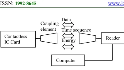
2.2 Components of Application System
RFID system consists of electronic tags, antenna, reader and host. The tag, non-contact IC card, needs to be set on the identified objects. It is composed of coupling elements and chips, and there are built-in antennas in the tag, which transmits and receives signals. The antenna transmits and receives wireless signals. The reader can send and receive commands, communicate with the host, and execute host command. The host sends user commands and displays received data.
2.2.1 Electronic tag
Electronic tag refers to the ultra-tiny little label composed of the IC chip and wireless communication antenna, whose built-in radio frequency antenna communicated with the reader. When the system works, the reader sends a query signal, the passive label rectifies to DC power to supply circuit within the tag after receiving the query signal, and the other part of the energy signal reflects back to the reader after modulated by the data stored within the electronic tag.
2.2.2 Reader
Reader is the core of RFID system; the basic role is to be an exchange link of the core data between forward channel and backward channel. The reader communicates with the application system. The reader modulates and decodes the signal sent by the label, and sent to the application system through USB, serial port and Ethernet port. The application system can send the appropriate commands to the reader and control the reader to complete the task. The reader can activate a number of standard labels within the effective radio frequency range, identify multiple tags at the same time and has anti-collision function.
2.2.3 Antenna
Antenna can receive and radiate radio frequency signal power of transceiver in the form of
electromagnetic waves. The antenna can be divided into shortwave, ultra short wave and microwave antenna according to work band, and it is divided into Omni directional and directional antennas according to directions [4].
2.3 Workflow
In the application, the electronic tag attaches to the items to be identified, when the items with electronic tag pass through the reading range, the reader automatically and non-contact takes the agreement identifying information distantly from the electronic label, so as to achieve the function of automatic identification and collection of identification information.
RF card system has the following specific work procedures.
(1) The writing and reading terminal continues to issue fixed-frequency electromagnetic waves to the surrounding;
(2) There is an LC series resonant oscillator circuit in the frequency radio card with specific frequency corresponding to the terminal, when it enters to the work area, LC resonant circuit will resonate in the electromagnetic excitation;
(3) Resonance makes the capacitance of the RF card accumulate charge, when the saving charge reaches a specified voltage, it can be used as power supply for the RF integrated circuit cards to provide operating voltage;
(4) The relevant control logic circuit of RF card decodes the received signal;
(5) According to decoding information, it determines the request from the writing and reading terminal, reads the relative information of memory or re-programming. When the capacitive of circuit card discharges, it sends the memory data and related information to the terminal to achieve a complete information exchange.
The structure of the system is shown in Fig. 1.
2.4 RFID Middleware
Figure 1. Entire structure of FRID system
It has two main roles, the first is to control writing device to work on schedule, and ensure cooperation and coordination of different writing devices. The second is to filter data according to certain rules, filter out most of the redundant data and transmit the truly effective data to the background system [5].
2.5 Features of RFID technology
RFID is an easy, simple, practical and flexible application technology, and if has unique advantages that the bar code, magnetic card, IC card and other identification technologies can not match.
2.5.1 Quick scan
The bar code can only scan one at a time, while RFID reader can identify a number of RFID tags.
2.5.2 Small size and diverse shape
RFID is not restricted by the size and shape, and not need to act in concert with fixed size and print quality. In addition, RFID tags can develop to smaller and more diverse forms to apply to different products.
2.5.3 Anti-pollution capability and durability The carrier of traditional bar code is paper, so it is vulnerable to pollution, but RFID has strong resistance for water, oil and chemicals. In addition, the bar code is attached to the plastic or cardboard packaging, so it is particularly vulnerable to breakage. RFID label stores data in the chip, so it can be free from fouling.
2.5.4 Be reused
The bar code can not be changed after printing, while RFID tags can be repeatedly added, modified, deleted to facilitate information updating.
2.5.5 Penetrating and non-barrier reading RFID can penetrate paper, wood, plastic and other non-metallic or non-transparent material when covered, and can carry out penetrating communication. The bar code scanner can only distinguish bar code closely when no objects.
2.5.6 Large data memory
The capacity of one-dimensional bar code is 50Bytes, and the maximum capacity of two-dimensional bar code is 2-3000 characters, while the maximum capacity of RFID is a number of Mega Bytes. With the development of memory vectors, data capacity also has growing trend. There are more and more data carried in the future articles, which will demand corresponding increasing in expanding capacity.
2.5.7. Security
Because RFID carries electronic information, and its data can be protected by password, it can not easily be forged or altered.
3. OVERALL DESIGN
Intelligent vehicle management system is an automated management platform of distributed vehicles, which is supported by intelligent devices, uses non-contact smart card to automatically verify the vehicle, uses wireless and wired networks to transmit signal, and uses server and terminal to process comprehensively.
3.1 Design Principles
The system design process should be from the practical application and follow the following points.
3.1.1 Usefulness
It should first consider the requirements of vehicle access and the need of practical application to ensure quick access, easy use, practical and efficient operation.
3.1.2 Stability
For an intelligent management system, stability is particularly important. When in the situation of management workstation failure, network communication interruption or controller failure, it can maintain normal and stable operation of parking system.
3.1.3 Security
To ensure the interests of users, it uses effective high-tech measures to prevent various forms of incomplete events. Meanwhile, the system operation design must be standardized to ensure safety of the system and management personnel.
3.1.4 Scalability
It refers that the system capacity and function can not only meet the current needs of users, but also expand easily, so as to protect the future expansion and upgrading and adding new features.
Contactless IC Card
Data
Time sequence
Energy Coupling element
Computer
3.1.5 Economy
In the case of meeting user needs, functional configuration can be optimized to reduce construction cost. In the future, the maintenance costs and daily management costs is low. The software can freely upgrade the user system regularly at the same time of updating.
3.2 Overall Structures
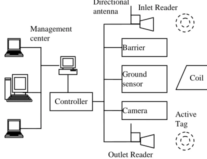
[image:4.612.94.301.526.685.2]According to the requirements of vehicle management system, it uses management mode of local area network. Its combination is flexible, and can achieve strict management of vehicle access. In this mode, the database server of the management system is on the server, and the control room is located in the middle of the import and export. Each control room is placed a management computer and a controller, and the controller contains the RFID controller and PLC controller. The two readers linked with RFID controller are placed in the exit and entrance to achieve the information read. In addition, the inlet and outlet are also placed two sense coils and a barrier. For long-term users, the RFID card should be placed on the left door of the car. The computer of each entrance is linked with the LAN of the community, thus whether the vehicle enter or leave from any gateway, the information of vehicle will be recorded real-time and saved to the central database. Management information system is combined with vehicle access control system, which achieves intelligent management. This will not only meet the requirements of convenient, fast and safety, but also improve service level of residential property, and lay the foundation for intelligent residential construction. The entire system design is shown in Fig. 2.
Figure 2. Structure Of Intelligent Vehicle Management System
When the vehicle with a radio card enter the door, it will automatically send messages, then the reader nearby will read the card information, and send to the system center to be checked. When the vehicle and information is correct, the photo shoot by the camera will check the license number, if all information is accurate, system center will send them to the controller to open the door, and otherwise, the door will not open.
If the car without RF cards enters, he needs to contact the security, send the information of the car and photo to the system center.
4. SYSTEM HARDWARE SELECTION
A vehicle management system has complex structure, of which the most important is RFID device.
4.1 RFID Devices
For RFID equipment selection and evaluation, we should consider from frequency, range and other aspects. RFID system consists of low-frequency system, high-frequency system, ultra-high frequency systems, and microwave system. The energy of low-frequency system is carried out by inductive coupling. It has strong penetrating ability to conducting media, but has short effect distance, low data transmission rate, low signal to noise ratio, and strong environmental sensitivity of the system. High-frequency system is to make the voltage change on the controller through load resistance connection and cut, and achieve amplitude modulation to antenna voltage through long-range sensor. The penetrating ability of the system is reduced, and may be absorbed in the transmission process, but it has large transmission distance. High-frequency system is often used for access control and applications of transmitting large amounts of data. Ultra-high frequency system and microwave system has long identification distance, fast speed, and is often used for train control and highway toll collection system.
The system is mainly used for vehicle identification of units and communities, the vehicle speed is relatively slow, and the distance is small, so it selects low-frequency RFID systems. According to the requirements, we choose Omron V600 Series RFID system with a relatively stable performance. V600 Series system is a high standard electromagnetic coupling RFID system with the operating frequency of 530 KHz. Its coding system is fully compliant with the EPC standard, communication speed is very fast. It has an excellent environmental adaptability, and can work
Inlet Reader
Active Tag Directional
antenna
Ground
sensor Coil
Barrier
Camera
Outlet Reader Controller
in the environment of high temperature. The system consists of RFID controller, read-write head and the RFID tag [6].
4.2 PLC Controller
Programmable logic controller is an electronic device designed for digital computing operation in industrial environments which have also been growing concern by many experts, and some successful application has been obtained [7]. The PLC controls various types of machinery or production processes through digital or analog input and output, and it is an important device to achieve circuit control. Its good performance will directly affect the normal operation of the system. Therefore, when select the equipment; we should consider execution speed of controller, communications and equipment compatibility.
Based on the above considerations, we use Omron CP1L series PLC which is a small, high-speed, multi-functional product. It can choose RS-232 or RS-422/485 ports, input and output can be expanded to 60 points, and the equipment adds function of pulse output, frequency positioning and Ethernet, which can fully meet the vehicle management demand of general user.
5. SYSTEM IMPLEMENTATION
5.1 Design of System Function Modules
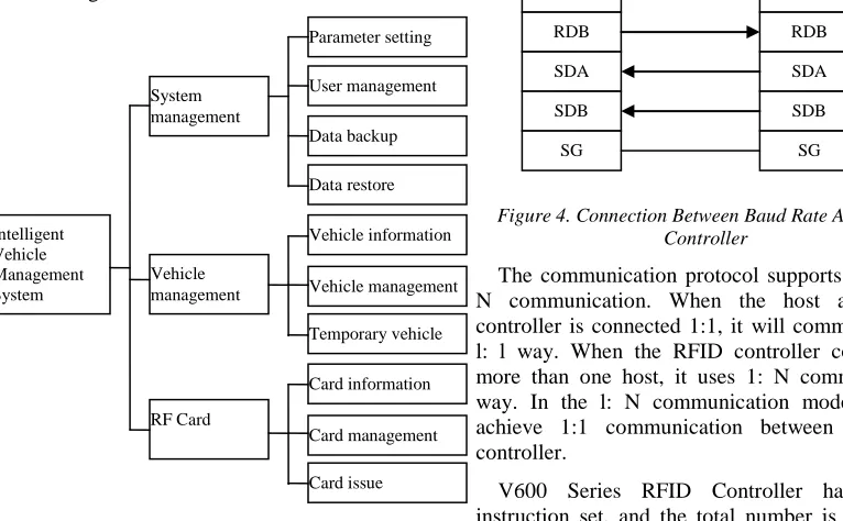
According to system functions, the entire system can be divided into three functional modules, as shown in Fig. 3.
Figure 3. Function Modules Of System
(1) System management. It can set user function permissions, backup and restore system data, and set system parameter.
(2) Vehicle management modules. It manages basic information of vehicle, and is responsible for temporary vehicle registration.
(3) RF card module. It mainly registers vehicle information, initializes the new card, and writes the basic information of the cardholder to the card.
5.2 Implementation of PLC Communication Function
5.2.1 Communication setting
It uses serial communication between PLC and RFID controllers, and according to RFID controller communication specifications, it carries out appropriate mode setting for CPlL serial port 1 and communication baud rate setting. The wiring of communication baud rate and RFID controller is shown in Fig. 4.
5.2.2 Communication protocol
[image:5.612.97.480.467.704.2]When the host computer communicates with RFID controller, it uses a dedicated SYSWAY communication protocol; the host computer sends communication command priority. After receiving, RFID controller firstly analyzes the command from the host, and then reads and writes RFID tags. After communication, RFID controller returns a response code to the host.
Figure 4. Connection Between Baud Rate And RFID Controller
The communication protocol supports l: l and l: N communication. When the host and RFID controller is connected 1:1, it will communicate in l: l way. When the RFID controller connects to more than one host, it uses 1: N communication way. In the l: N communication mode, we can achieve 1:1 communication between host and controller.
V600 Series RFID Controller has a rich instruction set, and the total number is 23, which can achieve flexible communication with host including communication command, general
RDA
RDB
SDA
SDB
SG
RDA
RDB
SDA
SDB
SG System
management
Intelligent Vehicle Management System
Vehicle management
RF Card
Parameter setting
User management
Data backup
Data restore
Vehicle information
Vehicle management
Temporary vehicle
Card information
Card management
communication sub-commands and host commands.
5.3 Implementation of RFID Reader Communication
The computer communicates with RFID controllers through MSComm control. Its communication protocol, command and data transmission format is the same as the communication between PLC and RFID controller. This paper only analyzes connection and implementation of communication.
5.3.1 Communication connection
Computer and Omron V600 Series RFID controller uses l: 1 link. It completes reading/ writing operations of RFID tags through serial communication. It uses connection program of handshake-free signal. This way is easy to connect, only needs one signal ground GND and two data lines, transmission line TXD and receiving line RXD. When wiring, the transmitter TXD and receiver RXD of the computer is connected with the same part of RFID controller respectively, both GND connect, each request lines RTS, allowance transmission lines shortcut. Control lines RTS and CTS self-link, and default the existence of the other signal to ensure the state into the handshake and can directly exchange data.
5.3.2. Add MSComm control
MSComm is ActiveX control of serial communication programming under simplified Windows provided by Microsoft, which can be easy to achieve communication, and program friendly for users [8].
5.4 Vehicle Access Control
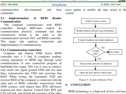
The requirements of vehicle access control are very simple. The workflow is as follows, when a vehicle closes to the door and into the reading range, the reader can obtain tag information automatically and send to the computer of monitoring center. After the system finds the database of the computer, if the verification is correct, surveillance camera will take pictures and store information into the computer, then the door will raise and allow the vehicle to pass. If a vehicle is illegal, the system will sound a warning to the guards on duty to deal with it accordingly [9]. System software flow is shown in Fig. 5.
For the temporary vehicle, we can issue a temporary tag, and when the vehicle leaves the door, the guard will be prompted for recycling. System interface includes system startup, temporary data input, data input, data deletion, data search and exit functions. These features can ensure that the
[image:6.612.88.521.66.390.2]users update or modify the data stored in the system.
Figure 5. System Software Flow
6. CONCLUSION
RFID technology is a high-tech of fast, real-time, fast acquisition and information processing, which has broad application prospects in production, security and other industries. Based on the analysis of RFID technology theory, this paper designs intelligent vehicle management system using Omron v600 series RFID and CPIL type PLC. This system not only can achieve automatic control of vehicle access, but also strengthen vehicle management and enhance the unit security, and collect information without manual procedures when the vehicle pass through the door. The simulation run of system shows that the software is reliable, result is good, and achieves the system design goals, which proves feasibility of the system, and better scalability. In short, the vehicle management system based on RFID technology saves manpower and has good economic benefits.
REFRENCES:
[1] Xu Jin, Luo Jie, “A Study Of Multi-Agent
Based Model For Urban Intelligent Transport Systems”, International Journal of Advancements in Computing Technology, vol. 4, no. 6, 2012, pp. 126-134.
[2] ZHAN Yan-jun, YANG Bi-feng, “RFID-based
Intelligent Vehicle Management System”, Microcomputer Information, vol. 26, no.2-2, 2010, pp.166-168.
Vehicle closes to door
Reader induces and gets tag information
Connect database and make judgment
No is Data
valid ? Give alarm
Take picture and store in database
[3] Yang Bifeng, Zhan Yanjun, “Design of RFID-based Intelligent Vehicle Management System”, Computer Measurement & Control, vol. 18, no.1, 2010, pp. 97-99.
[4] Li Yi, Li, Hongbo, “System Design Based on
RFID Technology for vehicle automatic management”, Microcomputer Information, vol. 21, no.10-2, 2005, pp. 153-154.
[5] HU Dong, “The Vehicle Automatic
Management System Based on Long-range RFID Technology”, Master Degree Dissertation, Taiyuan, Shanxi, China: North University of China, 2008.
[6] Wang Wei, “Community’s Vehicles access
management system based on RFID technology”, Master Degree Dissertation, Qingdao, Shandong, China: Qingdao University, 2008.
[7] Lv Shu-dong, “Study on Controlling Simulation
of Heat Pump Drying System Based on PLC”, Advances in Information Sciences and Service Sciences, Vol. 4, No. 19, 2012, pp. 151-158.
[8] Xu tong, Du Wenlong, “Application of RFID
technology in the safety management system of
vehicle access”, Science & Technology
Information, no.11, 2011, pp. 76-77.
[9] FU Peng-fei, YANG Zhong-gen, WANG