International Journal of Emerging Technology and Advanced Engineering
Website: www.ijetae.com (ISSN 2250-2459,ISO 9001:2008 Certified Journal, Volume 4, Issue 5, May 2014)
410
LLECLAIR: A Cross Layer Design to Optimize the
Performance of TCP in Wireless Networks
Prof Jay L. Borade
1, Prof Rajesh Bansode
21Asst Proff IT FRCRCE, India 2Asst Proff IT TCET, India
Abstract— Transmission Control Protocol (TCP) provides reliable and efficient way of communication in wired networks. Increased use of wireless technologies and the available variety of wireless mobile devices in the market demands for efficient technology for communication. TCP throughput however degrades over wireless links; the performance achieved by TCP can be improved through the use of cross-layer algorithms. In this paper an architecture is presented called as LLECLAIR which can act as a standard for cross layer design ÉCLAIR module in LLECLAIR provides the optimized merging of two or more layers whereas the LLCLMAP module in the proposed architecture provides
a solution for Congestion control in the wireless
communication.
Keywords— Automatic Repeat Request, Cross Layer Design, ÉCLAIR, LLCLAMP, Optimizing Sub System, Tuning Layers, Transmission Control Protocol /Internet Protocol.
I. INTRODUCTION
TCP /IP is an connection oriented byte stream transport protocol which is used by many end-user applications. The available standard protocols have the layered architecture [1]. However, layered architecture is best suited in the wired networks. Several problems arise when the TCP is used in the wireless networks, as the wireless networks have the dynamic behavior that affects reliability, fading / shadowing problems, mobility of the nodes, limited bandwidth and poor resource management.
To enhance the performance in the TCP protocol stack for wireless networks cross layer design method is developed [2][3][4]. Cross layer optimization is an escape from the normal layered concept of TCP/IP with virtually strict boundaries between the layers. Cross layer optimization removes the strict boundaries to allow communication between layers by permitting one layer to access the data of another layer to exchange information and enable interaction. The problem of network congestion is also considered as the main reason for poor performance of TCP in the wireless networks.TCP congestion control is performed on end to end basis. Here the receiver provides an ACK feedback to the sender.
Receiving of positive ACK from the receiver provides reliability of message send. The Congestion control algorithm provided by the TCP is window based. Congestion window (cwnd) controls the amount of data the sender is allowed to output to the network with the acknowledgement.
In order to prevent congestion loss, an active queue management is required to avoid buffer overflow and also a fair scheduling is required for allocating the bandwidth. To enhance the performance of the protocol stack a seamless mobility cross layer feedback algorithm is required.
These algorithms would need to be easily integrated with the existing protocol stacks. Cross layer designing approach provides feedback mechanism which can be used as a standard for easier development, deployment and maintenance of the wireless networks.
In this paper, an architecture named as LLECLAIR is proposed which provides a basic structure for implementing the cross layer feedback mechanism along with a solution for congestion control where the acknowledgement at the receiver is suppressed and is generated at the base station. Even the congestion measure is also calculated at the base station and is attached to the acknowledgment. The main
performance advantages are achieved through the
optimization of interlayer automatic repeat request (ARQ) scheme. This architecture also provides the components like Optimizing Subsystem (OSS) and the Tuning Layers (TL). OSS is the actual cross layer engine which consists of the Protocol Optimizer (PO). TLs provide the APIs to the POs for interacting with various layers and manipulating the protocol data structures.
This paper is organized as follows: related work for cross layer design is given in section II; overview of the ÉCLAIR architecture is given in section III; overview of LLCLAMP architecture is given in section IV; details of proposed system LLECLAIR is given in section V; Conclusion and summary for the paper is provided in section VI.
II. RELATED WORK
International Journal of Emerging Technology and Advanced Engineering
Website: www.ijetae.com (ISSN 2250-2459,ISO 9001:2008 Certified Journal, Volume 4, Issue 5, May 2014)
411 A cross-layer ARQ scheme is provided in [6] which enhance the protocol stack of the wireless sender and receiver which enables collaboration between the link and transport layer. A cross layer feedback optimization architecture which provides the easy development, deployment and maintenance of the layers, ÉCLAIR is given in [7]. An efficient architecture which provides the congestion control and congestion measure at the base station LLCLAMP is given in [8]. The LLECLAIR protocol merges the functionalities of the ÉCLAIR and LLCLAMP and provides a better optimization of TCP in wireless network.
III. OVERVIEW OF ECLAIRARCHITECTURE
The ÉCLAIR architecture is provided in [7] has the following design goals:
- Rapid Prototyping: Enable interfacing with existing stack without any significant changes in the existing stack.
- Minimum intrusion: Enable easy porting to multiple systems.
- Portability: Enable easy porting to multiple systems.
- Efficiency: Enable efficient implementation of cross layer feedback.
A. ÉCLAIR Architecture
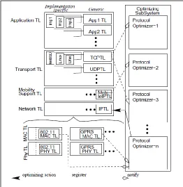
ÉCLAIR splits the cross layer system into two subsystems – Tuning Layers and Optimization Subsystem. Figure 1 from [7] shows the detailed architecture of ÉCLAIR.
- Tuning Layers (TLs): The purpose of a tuning layer is to provide and interface to the internals of a protocol. Data structure of the existing protocol stack is manipulated in the Tuning Layer. TL is further divided as generic and implementation specific sub layer, where the generic and implementation specific protocols for a particular layer are located.
- Optimizing Subsystem (OSS): The optimizing
subsystem contains the algorithms and data structures for cross layer optimizations. The OSS contains many Protocol Optimizers (POs). A PO contains the algorithm for a given cross layer optimization. PO decides the optimizing action to be taken based on the events occurring at various layers and current state of the protocol layer which is to be modified. The OSS executes concurrently with the existing protocol stack processing overhead.
IV. OVERVIEW OF LLCLAMPARCHITECTURE
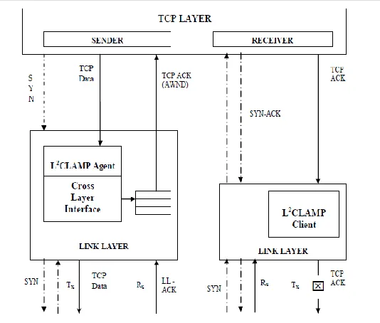
The LLCLAMP agent in Figure 2 from [8] suppresses outgoing LLCLAMP-TCP ACKs at the receiver side and generates them locally at the sender or base station. The basic idea in this architecture is to shift TCP ACK generation point from mobile receiver to the base station.
[image:2.612.322.584.149.418.2]Whenever a TCP data packet is detected, the LLCLAMP Agent in BS /AP, performs service rate, congestion measurement, received rate and calculates the AWND value, stores flow –related information such as flow sequence number carried by packet, port numbers, ACK flag and ACK sequence number, along with the AWND value. LLCLAMP agent calculates the desired size of the AWND window based on the values of congestion measure, received rate and RTT. To calculate congestion measure, a separate Sync packet is sent from the base station to the receiver and the acknowledgement for the Sync is received back by the sender, based on which the transmission time for each packet is calculated.
Figure 1: ÉCLAIR architecture
International Journal of Emerging Technology and Advanced Engineering
Website: www.ijetae.com (ISSN 2250-2459,ISO 9001:2008 Certified Journal, Volume 4, Issue 5, May 2014)
412
V. PROPOSED SYSTEM LLECLAIR
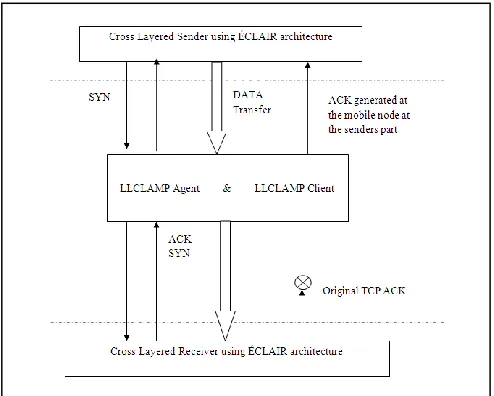
The proposed system LLECLAIR is a combination of the above mentioned ÉCLAIR and LLCLAMP. ÉCLAIR architecture is best for designing the cross layers on the sender and receiver sides, whereas the LLCLAMP architecture provides an efficient congestion free mechanism for communication. In the proposed protocol we have developed the ÉCLAIR protocol on the extreme ends where the actual sender and receiver are located and the LLCLAMP agent and LLCLAMP client modules are used for the purpose of communication between the sender and receiver. The following Figure 3 shows the architecture of the LLECLAIR protocol which is the combination of ÉCLAIR and LLCLAMP architecture in [7] [8].
LLECLAIR architecture provides dual benefit for communication in wireless network using the concept of cross layer design. LLCLAMP provides better congestion control mechanism but using CLAMP can only reduce the problem of congestion control. Every mobile wireless node present in wireless network will first develop the ÉCLAIR architecture on them. This architecture will provide the tuning layer and OSS to every node.
[image:3.612.321.586.134.416.2]Figure 4 below shows a simple example of wireless nodes communicating using the LLECLAIR protocol. Figure 4 shows there are 10 nodes and node N1 is communicating with node N5 and node N3 is communicating with node N10.
Figure 2: LLCLAMP architecture
[image:3.612.36.303.142.369.2]
Figure 3: LLÉCLAIR architecture
[image:3.612.321.588.513.654.2]International Journal of Emerging Technology and Advanced Engineering
Website: www.ijetae.com (ISSN 2250-2459,ISO 9001:2008 Certified Journal, Volume 4, Issue 5, May 2014)
413 All these are wireless or mobile nodes which keep on changing their location. Now if node N1 is communicating with node N5, firstly these nodes have to decide upon which layers and which protocols they would required for the communication. Suppose if node N1 uses the IP protocol of Network layer and ATM protocol from Data link layer, then by using the Tuning layer and Optimization Subsystem layers of the LLECAIR both the layers are merged with each other’s and the required data structure is created for the same which includes the type of packets, type of message queue, size of packets and others. Once the ÉCLAIR layer from LLECLAIR protocol develops the data structure and merges the required layers with the nodes, the communication process moves ahead considering the congestion controlled technique of the LLCLMAP.
Node N1 and N5 first will setup the data structure as mentioned above after which the sender N1 will send the SYN packet to the receiver N5, LLCLAMP agent and LLCLAMP client acts as the intermediate layer for communicating between the sender and receiver. N5 sends the SYNACK in response with the SYN bit sent by the N1. If both nodes are ready to transmit the data is send from the sender to receiver. LLCLAMP agent and LLCLMAP client provides reliable communication between two nodes. As the nodes are mobile LLCLAMP also locates the sender and receiver for the data transmission. Whenever the packets are received by the receiver the LLCLAMP client will send the ACK packet to the LLCLAMP agent and no hence no need of generating of the ACK packets by the receiver which saves even the communication time.
The communication flow of LLECLAIR protocol is shown in the Figure 5 above.
A. LLCLAMP Algorithm
LLECLAIR uses the LLCLAMP algorithm for doing calculation of congestion control which is as below:
Receive New Data Packet from Network If (Data Packet == TCP) then
Generate a TCP Acknowledgement with the respective fields.
Store it in the buffer.
Calculate the Congestion measure.
ps(q) =max ((q-a)/ c,0) (1)
Calculate the AWND window size
(2)
(3)
If ( w(tk)<0) or (3 Duplicate ACK’s) Stop slow start
Set w (tk +1) =w (tk)/2 end if
AWND (tk) min (w(tk), AWND) (4)
Add the information to the Stored ACK Buffer. Forward the TCP Data Packet for Transmission Wait for Link Layer Acknowledgement
if (LL-ACK received==yes) then
Pop the generated ACK from the buffer and transmit to the sender
else
Drop the ACK generated stored in the buffer end if
else
Forward the packet to the wireless node. end if
where
q – Current value of moving average
– Time instant of kth packet when received by MN
Δw ( ) – Change in window size α, β - smoothing factors
AWND ( ) – Actual Window size
d* - RTT of the flow in seconds (propagation delay + queuing delay)
– Service rate of a queue
d – Propagation delay
[image:4.612.43.290.487.685.2]q (t) = τ / b (amount of flow in bytes)
International Journal of Emerging Technology and Advanced Engineering
Website: www.ijetae.com (ISSN 2250-2459,ISO 9001:2008 Certified Journal, Volume 4, Issue 5, May 2014)
414
VI. SUMMARY AND CONCLUSION
In this paper, we presented LLECLAIR architecture for cross layer feedback and congestion controlled transmission of the data. This architecture has two main components ÉCLAIR module at the sender and receiver end and LLCLAMP module in between sender and receiver for communication. ÉCLAIR module consists of two main components which are tuning layer and Optimizing subsystem layer both together provides a simple architecture to merge any two or more layers on the TCP protocol in order to develop cross layer design for wireless networks. LLCLAMP avoids TCP ACK transmission over the wireless link through local generation of ACKs at the sender node or at the base station. The congestion measure is also calculated at the base station based on which the receiver advertised window is calculated. LLECLAIR provides a structured approach of cross layer design by using which the TCP performance can be optimized in the wireless networks.
Our future scope shall be to simulate the LLECLAIR protocol and compare it with some standard protocol such as AODV, DSR and others.
REFERENCES
[1] ITU, Information technology –OSI-Basic Reference Model, July
1994. X.200.W.-K.
[2] S. Rao and K. Sharma, ―Cross Layer protocols for Multimedia
Transmission in wireless networks‖, International Journal of Computer Science and Engineering Survey (IJCSES), vol.3, pp.15-28, June 2012.
[3] T. Mahmoodi, V. Friderikos, O. Holland and H. Aghvami, ―Cross
Layer Design to improve wireless TCP performance with Link-Layer Adaptation‖, IEEE, pp.1504-1508, 2008.
[4] M. Lee, M. Kang and J.Mo, ―A cross layer approach for TCP
optimization over wireless and mobile networks‖, Elsevier B.V, pp.2669-2675, 2008.
[5] V. Srivastava and M. Motani, ―Cross Layer Design: A Survey and
the Road Ahead‖, IEEE Communication Magazine, pp. 112-119, December 2005.
[6] D. Kliazovich, F.Granelli and M. Gerla, ―Performance improvement
in wireless networks using cross –layer ARQ‖, ELSEVIER Computer Networks 51, pp 4396-4411, June 2007.
[7] V. Raisinghani and S. Iyer, ―ÉCLAIR: An Efficient Cross Layer
Architecture for Wireless Protocol Stacks‖, WWC 2004.
[8] P. Sathaya and K. Murgan, ―Cross Layer Approach to Enhance TCP