This is a repository copy of
Delay-Robust Distributed Secondary Frequency Control: A
Case Study
.
White Rose Research Online URL for this paper:
http://eprints.whiterose.ac.uk/144279/
Version: Accepted Version
Proceedings Paper:
Alghamdi, S, Smith, N, Schiffer, J et al. (1 more author) (2019) Delay-Robust Distributed
Secondary Frequency Control: A Case Study. In: IEEE. IEEE PES PowerTech, 23-27 Jun
2019, Milano, Italy. IEEE . ISBN 9781538647226
https://doi.org/10.1109/PTC.2019.8810821
© 2019 IEEE. Personal use of this material is permitted. Permission from IEEE must be
obtained for all other uses, in any current or future media, including reprinting/republishing
this material for advertising or promotional purposes, creating new collective works, for
resale or redistribution to servers or lists, or reuse of any copyrighted component of this
work in other works.
[email protected] https://eprints.whiterose.ac.uk/
Reuse
Items deposited in White Rose Research Online are protected by copyright, with all rights reserved unless indicated otherwise. They may be downloaded and/or printed for private study, or other acts as permitted by national copyright laws. The publisher or other rights holders may allow further reproduction and re-use of the full text version. This is indicated by the licence information on the White Rose Research Online record for the item.
Takedown
If you consider content in White Rose Research Online to be in breach of UK law, please notify us by
Delay-Robust Distributed Secondary Frequency
Control: A Case Study
Sultan Alghamdi
∗, Nathan Smith
∗, Johannes Schiffer
§, Petros Aristidou
∗∗School of Electronic and Electrical Engineering, University of Leeds, Leeds LS2 9JT, UK
§Institute of Electrical and Thermal Energy Systems, Brandenburg University of Technology Cottbus-Senftenberg
Emails:{elsalg, el16njs, p.aristidou}@leeds.ac.uk, [email protected]
Abstract—With the purpose of enabling a low-carbon future, power systems worldwide are undergoing major transformations. These developments require new advanced control and operation approaches to ensure a stable and efficient system operation. Distributed consensus-based algorithms are a promising option to provide the necessary flexibility and scalability to cope with these challenges and have, thus, been widely investigated in the literature. Yet, most available results are limited to scenarios with reduced-order models and ideal communication. Motivated by this, we perform a case study using a detailed dynamic model of the well-known Nordic test system equipped with a consensus-based distributed secondary frequency controller. Our main objectives are to analyse the robustness of the closed-loop system with respect to unmodelled (voltage and higher-order generator) dynamics as well as communication delays. To facilitate the later property, we employ robust-stability conditions in the control design. Then, the performance of the proposed controller is assessed through detailed dynamic simulations covering several disturbances leading to large frequency and voltage excursions.
Index Terms—Distributed control, consensus algorithms, sec-ondary frequency control.
I. INTRODUCTION
A. Motivation and Related Work
Power systems are seeing a growing demand to integrate more renewable energy sources (RES) for a more sustainable, low-carbon future. The rise in RES penetration means there is also an increase in power-electronic-interfaced components re-placing conventional thermal generation units, hence reducing the total system inertia. This leads to new stability and security concerns involving frequency deviation and restoration, after a significant disturbance has occurred. Therefore, there is a need for advanced solutions through the use of new technologies and control approaches.
Regulating the steady-state frequency to the nominal value is required to maintain the balance between real-time genera-tion and load. The latter is tradigenera-tionally achieved by hierarchi-cal control layers: primary, secondary and tertiary control [1]. The primary control is a proportional control that acts fast to stabilize the frequency in a decentralized fashion but cannot perform steady-state frequency restoration. Secondary frequency control adjusts the active power setpoints to com-pensate for the steady-state frequency deviation which results from the primary control operation and the disturbances.
The development of cyber-physical power systems compris-ing the combination of power systems and communication networks could promote new control techniques in this area
and aid in reaching secondary frequency control goals by the utilisation of distributed communication architectures.
Conventionally, secondary frequency control is realized through a centralized scheme termed Automatic Generation Control (AGC), where the area control error is transmitted to the data center to be analyzed. Then new setpoints are broad-casted to each generator [2]. The resilience of future power systems is limited by the reliance of centralized approaches on a single control center; thus, making them vulnerable to single point failures. In addition, the need to minimise the complexity of communication infrastructures to achieve better scalability, makes centralized schemes inefficient. These challenges can be addressed with the use of new, distributed, schemes [3].
As a consequence, there is a need for transforming the power system from a centralized control scheme to a dis-tributed architecture. To this end, much work has been dedicated to employing distributed control algorithms such as consensus approaches [4]–[6] and primal-dual gradient-based algorithms [7], [8] that incorporate both frequency restoration and optimal generator dispatch. The work in this paper considers consensus-based algorithms for secondary frequency control which rely on peer-to-peer communication where each generation unit exchanges information with neigh-bouring participating generators. In practice, the consensus-based controller is simpler to implement than the primal-dual algorithm and also does not require prior knowledge of the actual load demand nor the generator parameters and power flows. Furthermore, consensus-based control can guarantee an optimal steady-state resource allocation (with standard quadratic generation cost functions).
B. Contributions
Based on the above discussion, our paper provides for the first time an extensive case study that evaluates the per-formance of a consensus-based secondary frequency control scheme on a realistic, full-detailed, medium-scale power sys-tem under the explicit consideration of communication delays. Furthermore, it is empirically shown that the conditions for delay robustness established previously by part of the authors in [14] also could guarantee robust stability in the presence of additional unmodelled dynamics. Compared to the related work [6], [15], our case study is not only limited to verify the steady-state frequency restoration with economic dispatch but, in addition, explores the impact of communication delays as well as the interaction of the controller with unmodelled voltage phenomena. Our case study is performed on the Nordic test system [16] and simulated with the software RAMSES.
II. OPTIMALCONSENSUS-BASEDFREQUENCYCONTROL
In this section, we present some essential background in-formation on optimal resource allocation and delay-robustness of the employed consensus-based controller.
A. Reduced Power System Model
For the control development, we represent the power net-work using the Kron-reduction method [1] as a connected and undirected graph with set of nodes N ={1,2, . . . , n}. We assume that at each node a generator is connected and assign a phase angle θi:R≥0→R and a relative frequency ωi= ˙θi−ωd, whereωd∈R≥0 is the desired (nominal)
net-work frequency, to each uniti∈ N.It is convenient to define the vectors θ=col(θi)andω=col(ωi). Moreover, we make
the following standard assumptions: the voltage amplitudes
V ∈Rn
≥0 at all nodes are constant and the transmission line
impedances are purely inductive [1]. With these assumptions, two nodes i and k are connected via a non-zero suscep-tance Bik∈R<0. If there is no line between i and k, then Bik= 0. We denote the set of neighboring nodes of nodeiby
Ni={k∈ N |Bik= 0}. The active power flow can be written
as follows P :Rn→Rn,
P(θ) =∇U(θ),
where the potential functionU :Rn →Ris given by
U(θ) =− X {i,k}∈[N]2
|Bik|ViVkcos(θik).
Moreover, the electromechanical generator dynamics can be compactly written as
˙
θ=ω,
Mω˙ =−Dω− ∇U(θ) +Pnet+Pm,
(1)
where Pm:R≥0→Rn is the mechanical power and Pnet=col(Pd
i −GiiVi2), wherePid ∈Rdenotes the nominal
power injection setpoint andGiiVi2, Gii∈R≥0, represents the
active power demand at thei-th node. Furthermore, the diago-nal and positive definite matricesD∈Rn×n andM ∈Rn×n
denote the damping and inertia coefficients, respectively. Before introducing the turbine-governor dynamics as well as to motivate the need for a consensus-based secondary control
law, we will study the steady-state frequency deviation of the system (1). Suppose that the solution of the system (1) converges to a synchronous motion with ωs=1
nω∗, where ω∗ is constant. Then, ω∗ is obtained from
1⊤
nMω˙
s= 0 ⇒
ω∗= 1 ⊤
nPnet+1⊤nPms
1⊤nD1n , (2) where we have used the fact that 1⊤
n∇U(θ) = 0.Clearly, in
order to obtain a zero stationary frequency deviation, the total generated power needs to match the total consumption. In the present paper, we aim at achieving this classical secondary control objective by simultaneously allocating the stationary secondary control injections in an optimal fashion, i.e. by solving an economic dispatch problem online. Therefore, we introduce the following optimization problem [17]:
min
Ps m
1 2(P
s m)⊤AP
s m,
subject to1⊤nPnet+1⊤nPms = 0,
(3)
where A=diag(Aii)∈Rn×n is a diagonal positive definite
weighting matrix. Hence, the cost function is quadratic and strictly convex. It can be seen from (2) that satisfying the constraint in (3) guarantees steady-state frequency restoration. The optimal solution to (3) is given by [4], [17], [18]
Pms =αA−
11
n, α=
1⊤
nPnet
1⊤nA−11n. (4) Since Pm is the output of the turbine-governor system, we
next introduce standard second-order turbine-governor dynam-ics together with a suitable distributed consensus-based sec-ondary frequency controller, such that the stationary solutions
Ps
m of the closed-loop power system correspond to optimal
solutions of (3).
B. Turbine-Governor Dynamics
The speed of a synchronous generator is determined by the speed of the prime mover. One of the well-known prime movers is the steam turbine. The speed of the steam turbine is controlled by the speed governor that senses the speed deviation and converts it into an appropriate valve action [19]. It is common in stability analyses to use a simplified model for the steam turbine-governor model to facilitate the stability analysis such as the TGOV1 model, see [20]. In this paper, we use a modified version of the TGOV1 [19] together with a secondary frequency control signal which will be used to achieve steady-state frequency restoration.
The physical dynamics of the steam turbine-governor can be written as follows
TmP˙m=−Pm+Ps,
TsP˙s=−Ps−K−1ω+p,
(5)
wherePs:R≥0→Rn is the steam power andp:R≥0→Rn
is the secondary control signal. Furthermore, the diagonal and positive definite matrices K∈Rn×n, T
m∈Rn×n and Ts∈Rn×ndenote the droop gains, governor time and turbine
time constants, respectively.
C. Optimal Consensus-Based Frequency Control
power system given by (1) and (5)
Tpp˙=−p+Pm−(In−K−1)ω−ALAp, (6)
where the controller (6) is associated with an undirected con-nected communication network represented by the Laplacian matrix L ∈Rn×n enabling distributed information exchange between the generators. The set of undirected edges of the communication graph is denoted by E and its cardinality by |E|. Furthermore, the diagonal positive definite matrix
Tp∈Rn×n denotes the controller time constants. It has been
shown in [4], [6], [17], that - if appropriately tuned - the control (6) is able to restore the frequency to its nominal value, that is, limt→∞kωi−ωdk= 0 for alli∈ N. In addition, it
was shown in [6], [17] that in steady-state Ps
m=ps and that
the power injections of all generation units satisfy the identical marginal cost requirement, i.e.,
AiiPm,is =AkkPm,ks ∀i∈ N, ∀k∈ N. (7)
Consequently, the matrix A is usually fixed by economic considerations and the stationary secondary control power injections correspond to optimal solutions of (3).
Guaranteeing robustness with respect to communication delays is essential for the implementation of (6) since delays pose a severe threat to the power system performance. Thus, we consider that the message sent from generation uniti∈ N to generation unit k ∈ N over the m-th communication link is subjected to a constant communication delay τm>0.
In order to introduce the closed-loop system with commu-nication delays compactly, we follow [13], [14] and introduce the matrices Lm,m= 1, . . . ,2|E|,
L=
2|E|
X
m=1
Lm. (8)
Now, we define the vector x=col(Pm, Ps, p)∈R3n as well
as the matrices
T =blkdiag(Tm, Ts, Tp), A¯=blkdiag(A, A, A), (9)
Φ =
In −In 0
0 In −In
−In 0 In
(10)
and
Ψm= ¯Ablkdiag(0,0, Lm) ¯A. (11)
Then, by combining (1), (5) with (6), the closed-loop dynamics with delays are given by
˙
θ=ω,
Mω˙ =−Dω− ∇U(θ) +Pnet+
In 0n×2n
x,
Tx˙=−Φx−
2|E|
X
m=1
Ψmx(t−τm)
−
0
K−1 In−K−1
ω. (12)
As usual [12]–[14], we assume the following.
Assumption 1: The system (12) possesses an equilibrium point col(θs,0
n, xs)∈R5n, such that
|θis−θ s k|<
π
2 ∀i∈ N, ∀k∈ Ni.
D. Delay-Robust Stability Condition
Following [13], [14], let W ∈ R3n×3n−1, such that
W⊤T12A¯−113n=03n−1 and introduce the two matrices
¯
Φ =W⊤T−12ΦT−12W, (13)
¯
Ψm=W⊤T−
1
2ΨmT−12W. (14) We then employ the following result for designing the gains of the controller in (12), the proof of which is given in [14].
Proposition 1: Consider the system (12). Fix A, K, L, T
and D as well as τm ∈ R>0. Suppose that for all Ψm
de-fined in (11), there exist matricesRm>0∈R(3n−1)×(3n−1), Sm > 0 ∈ R(3n−1)×(3n−1), P > 0 ∈ R(3n−1)×(3n−1), P2∈R(3n−1)×(3n−1),P3>0∈R(3n−1)×(3n−1)satisfying
Q=
−D Q12 Q13 0n×(3n−1)
∗ Q22 Q23 Q24
∗ ∗ Q33 Q34
∗ ∗ ∗ −S−R
<0, (15)
where
R=blockdiag(Rm), S=blockdiag(Sm),
Q12=1
2
In 0n×2n
T−12W−0 K−1 In−K−1T−12W P2,
Q13=−0 K−1 In−K−1T−
1 2W P3,
Q22=−P2⊤Φ¯−Φ¯⊤P2+ 2|E|
X
k=1 Sk−
2|E|
X
k=1 Rk,
Q23=−Φ¯⊤P3+P−P2⊤, Q24= ¯
Q24,1. . .Q¯24,2|E|,
¯
Q24,m=Rm−P2⊤Ψ¯m, Q33=−P3−P3⊤+ 2|E|
X
k=1 τk2Rk,
Q34=Q¯34,1. . .Q¯34,2|E|, Q¯34,m=−P3⊤Ψ¯m.
Then, the equilibrium point col(θs,0
n, xs)∈R5n is locally
uniformly asymptotically stable (modulo rotational symmetry).
III. TESTSYSTEM ANDRESULTS
Fig. 1. Schematic representation of the Nordic test system taken from [16]
A. Implementation of Secondary Frequency Controller
In this section, we choose the gain of the distributed sec-ondary frequency controller (6) for the described test system based on Section II. The distributed control is implemented at five of the thermal generators in the Central area (g6, g7, g14, g15, and g16) by replacing the constant mechanical power with the modified TGOV1 governor described by (5) and (6). The North area generators are equipped with hydraulic turbines.
For the communication network topology shown in Fig. 1 and for a maximum communication delay of200ms, we select the controller parameters Tp as follows. First, we form the
matrixLin (6) based on the communication network topology and the matrixAin (6) based on the generator marginal costs. Then, we define Tp = 0.041κA, where0.04 is the droop gain
for the primary control, κ∈ R>0 is a tuning parameter and
we set the communication delay to the maximum allowed
τm=τ = 200ms. Then, we select a large initial value of κ
(that is, a smallTpand fast-acting controller) and decrease its
value until the conditions (15) become feasible. This procedure gives us the fastest acting controller that satisfies the delay-robustness conditions. Moreover, this choice of TP allows
that generators with small cost coefficients (i.e., small Aii)
will react faster than the ones with large cost coefficients (i.e., largeAii). Fig. 2 provides a feasibility map of the
stabil-ity analysis conditions in (15) for the specific test system for
0 50 100 150 200
0.1 0.2 0.3 0.4 0.5
[s
]
Fig. 2. The feasibility map of condition (15) with different maximum communication delays.
0 100 200 300 400 500 600 700 800
Time [s]
-0.45 -0.3 -0.15 0 0.05
With Controller Without Controller With Controller (1.79 )
Fig. 3. Case 1: Frequency deviation
0 100 200 300 400 500 600 700 800
Time [s]
-0.35 -0.25 -0.15 -0.050 0.05
[image:5.612.309.566.81.378.2]With Controller Without Controller
Fig. 4. Case 2: Frequency deviation
different time delays and tuning parameter κ. The conditions are feasible in the shaded regions.
The feasibility of the analysis conditions (15) were imple-mented in MATLAB by using Yalmip [21] and Mosek [22] while all the dynamic simulations below were carried out using the simulation software RAMSES [23].
B. Case 1: Trip of 300MW Generatorg2in North Area
In this case, the 300MW thermal generator g2 is tripped at t= 100s in the North area resulting in a frequency devi-ation (∆ω) that triggers the primary frequency response and the distributed secondary frequency controller. The frequency response is shown in Fig. 3, both with and without the proposed secondary frequency controller. We can see that in both variants the system is stable after the primary responses but in the second one, the proposed controller quickly restores the frequency to its nominal value, as desired. Furthermore, in order to investigate the conservativeness of the proposed condition in Proposition 1, we increase the value ofκ, i.e. the response speed of the controller in RAMSES, while the value of the communication delays τm=τ= 200ms is fixed. We
0 100 200 300 400 500 600 700 800
Time [s]
0.8 0.9 1
[image:6.612.53.297.80.159.2]With Controller Without Controller
Fig. 5. Case 2: Bus voltage deviation at bus 1044 in Central area
0 200 400 600 800
Time [s] 2800
3000 3200 3400 3600
With Controller Without Controller
Fig. 6. Case 2: Total active power output from the participating generators
in the present scenario), but fairly accurate if the equilibrium phase angle differences are larger.
C. Case 2: Trip of 750MW Generatorg8 in North Area
In this case, the large 750MW thermal generator g8 is tripped in the North area at t= 100s. Fig. 4 shows the frequency deviation both with and without the controller. It can be seen that without the secondary frequency controller the system collapses at t≈ 240s. The generation lost in the North causes depressed voltages in the Central area. As the voltages are restored (due to the combined effect of generator AVR and OLTCs actions), so is the load power consumption. The combined effect leads to a long-term voltage collapse [24], as shown in Fig. 5.
When the secondary frequency controller is used, the active power injected in the Central area as a response to the under-frequency deviation, stabilises the system and restores the frequency to its nominal value. This can be seen in Fig. 6 in which the total active power output of the generators participating in the secondary frequency control is shown.
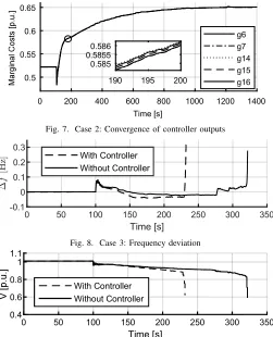
Finally, Fig. 7 shows the controller exchanged variables reaching consensus in steady state after small deviations (see Fig. 7, zoom) right after the disturbance.
D. Case 3: Loss of Major Corridor Line
In the considered test system, active power is transferred from the North area (where most of the generation is located) to the Central area (where most of the load is located). In this case, we trip a branch located in the main corridor linking the Central and the North areas of the system, 4032-4044 in Fig. 1. This change limits the ability of the transmission system to evacuate power to the Central area.
First, this leads to a surplus of power in the North and a deficiency in the Central area. Consequently, we observe an initial over-frequency (see Fig. 8) accompanied with depressed voltages in the Central area (see Fig. 9). Later, the voltages in the Central area start being restored (along with the load power demand) and the frequency decreases below the nominal one. This scenario leads to a long-term voltage collapse, driven by the load restoration and the generator over-excitation limits.
0 200 400 600 800 1000 1200 1400
Time [s] 0.5
0.55 0.6 0.65
g6 g7 g14 g15 g16
190 195 200
[image:6.612.313.564.84.394.2]0.585 0.58550.586
Fig. 7. Case 2: Convergence of controller outputs
0 50 100 150 200 250 300 350
Time [s]
-0.1 0 0.1 0.2 0.3
With Controller Without Controller
Fig. 8. Case 3: Frequency deviation
0 50 100 150 200 250 300 350
Time [s] 0.4
0.6 0.8 1 1.1
[image:6.612.56.294.182.265.2]With Controller Without Controller
Fig. 9. Case 3: Bus voltage of bus 1044 in Central area
0 50 100 150 200 250 300 350
Time [s]
2300 2500 2700 2900 3100
With Controller Without Controller
Fig. 10. Case 3: Total active power output from the participating generators
However, it can be seen from Figs. 8 and 9 that the proposed controller accelerates the system collapse.
The reasoning for the accelerated collapse is that the sec-ondary controller reacts to the initial over-frequency by reduc-ing the output power of the participatreduc-ing generators. Therefore, the power injected in the Central area is reduced, leading to a further reduction in bus voltages and accelerating the system collapse. Fig. 10 shows the total active power output of the generators participating in the secondary frequency control.
E. Discussion
[image:6.612.317.559.421.498.2]effective in this scenario, despite the presence of unmodelled system dynamics.
In Cases 2 and 3, the frequency dynamics initiated by the disturbance strongly interact with the long-term voltage dynamics driven by the load restoration mechanisms and the generator limits, leading to a complex dynamical interplay. This voltage-driven behaviour is not modelled in the controller analysis and, as the case study reveals, results in unforeseen system behaviours. In Case 2, the long-term voltage dynamics coincide with an under-frequency excursion, thus the controller response supports the system restoration by injecting more active power in the Central area. On the contrary, the behaviour of the controller in Case 3 leads to an accelerated system collapse due to the over-frequency excursion right after the disturbance that reduces the power injected in the Central area, thus further depressing the voltages.
Overall the presented case study analysis demonstrates that the proposed consensus-based secondary frequency control law (6) provides a flexible alternative to the standard AGC with the advantages of a fully distributed implementation and of combining frequency restoration with economic dispatch in real-time. The latter property may, e.g., also be used to enable peer-to-peer electricity markets [25].
But our investigations also show that the decoupling as-sumption between frequency and voltage dynamics, which is usually invoked when designing secondary frequency con-trollers [3], [4], [6], [7], [9], [14], can degrade the system performance in the presence of pronounced voltage dynamics following a disturbance. It is thus essential to be cautious when implementing the controller without considering such additional dynamics, in order to avoid deteriorating the overall system stability.
IV. CONCLUSIONS
We have investigated the performance of a consensus-based secondary frequency control via a case study on a detailed dynamic model of the Nordic test system. Two main aspects of interest were the robustness with respect to communication delays and with respect to unmodelled (voltage and higher-order generator) dynamics. Therefore, the controller has been designed by means of the delay-robust stability conditions derived in [14].
We have found that in the event of generator outages the steady-state frequency restoration was achieved in an optimal manner also in the presence of communication delays and unmodelled dynamics. Thus, the conditions in [14] were effi-cient. However, it was also shown that when complex voltage dynamics – not modelled in the control analysis phase – dominate the system behaviour, the controller might behave in an unexpected manner (stabilising or accelerating the system collapse).
Future work will therefore include the consideration of voltage dynamics, generator location and network topology in the analysis of the closed-loop performance to further improve the system resilience and robustness with respect to complex dynamic phenomena. Moreover, we will conduct a study to compare the performance of the proposed distributed controller
with the standard centralized AGC under communication de-lays.
REFERENCES
[1] P. Kundur,Power system stability and control. McGraw-Hill, 1994. [2] J. Machowski, J. Bialek, J. R. Bumby, and J. Bumby, Power system
dynamics and stability. John Wiley & Sons, 1997.
[3] C. Zhao, E. Mallada, S. H. Low, and J. Bialek, “Distributed plug-and-play optimal generator and load control for power system frequency regulation,”Int. J. Electr. Power Energy Syst., 2018.
[4] S. Trip and C. D. Persis, “Distributed optimal load frequency control with non-passive dynamics,”IEEE Trans. Control Netw. Syst., vol. PP, no. 99, pp. 1–1, 2017.
[5] J. Schiffer and F. D¨orfler, “On stability of a distributed averaging PI frequency and active power controlled differential-algebraic power system model,” inECC. IEEE, 2016, pp. 1487–1492.
[6] A. Kasis, N. Monshizadeh, and I. Lestas, “A novel distributed secondary frequency control scheme for power networks with high order turbine governor dynamics,” inECC, 2018, pp. 2569 – 2574.
[7] T. Stegink, C. De Persis, and A. van der Schaft, “A unifying energy-based approach to stability of power grids with market dynamics,”IEEE Trans. Autom. Control, vol. 62, no. 6, pp. 2612–2622, 2017.
[8] N. Li, C. Zhao, and L. Chen, “Connecting automatic generation control and economic dispatch from an optimization view,”IEEE Trans. Control Netw. Syst., vol. 3, no. 3, pp. 254–264, 2016.
[9] L. Jiang, W. Yao, Q. Wu, J. Wen, S. Chenget al., “Delay-dependent stability for load frequency control with constant and time-varying delays,”IEEE Trans. Power Syst., vol. 27, no. 2, p. 932, 2012. [10] H. Bevrani and T. Hiyama, “A control strategy for LFC design with
communication delays,” inIPEC, 2005, pp. 1087–1092 Vol. 2. [11] C. K. Zhang, L. Jiang, Q. H. Wu, Y. He, and M. Wu, “Delay-dependent
robust load frequency control for time delay power systems,” IEEE Trans. Power Syst., vol. 28, no. 3, pp. 2192–2201, 2013.
[12] S. Alghamdi, J. Schiffer, and E. Fridman, “Distributed secondary fre-quency control design for microgrids: Trading off L2-gain performance
and communication efforts under time-varying delays,” inECC, 2018, pp. 758 – 763.
[13] J. Schiffer, F. D¨orfler, and E. Fridman, “Robustness of distributed aver-aging control in power systems: Time delays & dynamic communication topology,”Automatica, vol. 80, pp. 261–271, 2017.
[14] S. Alghamdi, J. Schiffer, and E. Fridman, “Conditions for delay-robust consensus-based frequency control in power systems with second-order turbine-governor dynamics,” inCDC, 2018, pp. 786–793.
[15] C. Zhao, E. Mallada, S. H. Low, and J. Bialek, “Distributed plug-and-play optimal generator and load control for power system frequency regulation,” Int. J. Electr. Power Energy Syst., vol. 101, pp. 1 – 12, 2018.
[16] T. Van Cutsem, M. Glavic, W. Rosehart, J. Andrade dos Santos, C. Ca˜nizares, M. Kanatas, L. Lima, F. Milano, L. Papangelis, R. An-drade Ramos et al., “Test systems for voltage stability analysis and security assessment,” IEEE, Tech. Rep., 2015.
[17] S. Trip, M. B¨urger, and C. De Persis, “An internal model approach to (optimal) frequency regulation in power grids with time-varying voltages,”Automatica, vol. 64, pp. 240–253, 2016.
[18] F. D¨orfler, J. W. Simpson-Porco, and F. Bullo, “Breaking the hierarchy: Distributed control and economic optimality in microgrids,”IEEE Trans. Control Netw. Syst., vol. 3, no. 3, pp. 241–253, 2016.
[19] A. R. Bergen,Power systems analysis. Pearson Education India, 2009. [20] P. Pourbeiket al., “Dynamic models for turbine-governors in power system studies,”IEEE Task Force on Turbine-Governor Modeling, 2013. [21] J. L¨ofberg, “YALMIP : a toolbox for modeling and optimization in MATLAB,” in IEEE Int. Symposium on Computer Aided Control Systems Design, Sept. 2004, pp. 284 –289.
[22] M. ApS, The MOSEK optimization toolbox for MATLAB manual. Version 8.0.0.64, 2017.
[23] P. Aristidou, D. Fabozzi, and T. Van Cutsem, “Dynamic simulation of large-scale power systems using a parallel schur-complement-based decomposition method,”IEEE Transactions on Parallel and Distributed Systems, vol. 25, no. 10, pp. 2561–2570, 2014.
[24] T. Van Cutsem and C. Vournas, Voltage Stability of Electric Power Systems. Springer US, 1998.
![Fig. 1. Schematic representation of the Nordic test system taken from [16]](https://thumb-us.123doks.com/thumbv2/123dok_us/1768296.130624/5.612.70.277.71.411/fig-schematic-representation-nordic-test-taken.webp)