UNIVERSITI TEKNIKAL MALAYSIA MELAKA
DEVELOPMENT OF UNINTERRUPTIBLE POWER SUPPLY
USING VARIABLE VOLTAGE REGULATOR FOR LOW
POWER DEVICES
This report is submitted in accordance with the requirement of the Universiti Teknikal Malaysia Melaka (UTeM) for the Bachelor’s Degree of Electronics
Engineering Technology (Telecommunication) with Honours
by
MOHAMAD AFFENDI BIN AMRAN
B071410122
920823-06-5035
FACULTY OF ENGINEERING TECHNOLOGY
9l!i~~I
~µ~,.s-:-v·~J\
UNIVERSITI TEKNIKAL MALAYSIA MELAKA
UNIVERSITI TEKNIKAL MALAYSIA MELAKA
BORANG PENGESAHAN STATUS LAPORAN PROJEK SARJANA MUDA
TAJUK: Development Of Uninterruptible Power Supply Using Variable Voltage Regulator
SESI PENGAJIAN: 2017/18 Semester 1
Saya MOHAMAD AFFENDI BIN AMRAN
mengaku membenarkan Laporan PSM ini disimpan di Perpustakaan Universiti Teknikal Malaysia Melaka (UTeM) dengan syarat-syarat kegunaan seperti berikut:
1. Laporan PSM adalah hak milik Universiti Teknikal Malaysia Melaka dan penulis. 2. Perpustakaan Universiti Teknikal Malaysia Melaka dibenarkan membuat salinan
untuk tujuan pengajian sahaja dengan izin penulis.
3. Perpustakaan dibenarkan membuat salinan laporan PSM ini sebagai bahan pertukaran antara institusi pengajian tinggi.
4. **Sila tandakan ( ./)
D
D
D
SULIT TERHAD TIDAK TERHAD Alamat Tetap:(Mengandungi maklumat yang berdarjah keselamatan atau kepentingan Malaysia sebagaimana yang termaktub dalam AKTA RAHSIA RASMI 1972)
(Mengandungi maklumat TERHAD yang telah ditentukan oleh organisasi/badan di mana penyelidikan dijalankan)
Disahkan oleh:
Cop Rasmi:
NO 477, KAMPUNG BERKAT SATU,
26500 MARAN,
PAHANG DARUL MAKMUR.
Tarikh: Tarikh: ~~~~~~~~~~
~~~~~~~~~~-** Jika Laporan PSM ini SULIT atau TERHAD, sila lampirkan surat daripada pihak berkuasa/organisasi
iii
DECLARATION
I hereby, declared this report entitled “Development of Uninterruptible Power Supply Using Variable Voltage Regulator” is the results of my own research except as cited
in references.
\
Signature : ………
Author’s Name : Mohamad Affendi Bin Amran
iv
APPROVAL
This report is submitted to the Faculty of Engineering Technology of UTeM as a partial fulfilment of the requirements for the degree of Bachelor of Electronics Engineering Technology (Telecommunications) with Honours. The member of the supervisory is as follow:
………
(En. Mohd Anuar Bin Adip)
v
ABSTRAK
vi
ABSTRACT
vii
DEDICATION
viii
ACKNOWLEDGEMENT
Alhamdulillah, thank you Allah because of his blessing, I finally complete and finish my PSM 2 successfully. With great pleasure, I want to take this opportunity to express my heartfelt gratitude to all people who helped in making this major project work a grand success.
I was grateful to Mr. Mohd Anuar Bin Adip, lecturer of Fakulti Teknologi Kejuruteraan (FTK) UTeM for his valuable suggestions and guidance during the execution of this project and also for giving me moral support throughout the period of our study in UTeM. I believe that, without his knowledge and assistance, I will be lost into my wrong turn.
ix
TABLE OF CONTENTS
Abstrak v
Abstract vi
Dedication vii
Acknowledgment viii
Table of Contents ix
List of Figures xii
List of Tables xiii
CHAPTER 1: INTRODUCTION 1
1.0 Introduction 1
1.1 Background of Project 1
1.2 Problem Statement 2
1.3 Objectives 2
1.4 Scope of Project 2
1.5 Summary 2
CHAPTER 2: LITERATURE REVIEW 3
2.0 Introduction 3
2.1 Previous Project Analysis 3
x 2.2.4 Next-Generation Multi-Functional Modulator intelligent UPS for
smart grid 5
2.2.5 Impact of temperature on the efficiency of double-conversion
UPS 6
2.2.6 Double-conversion UPS efficiency under varying mains
conditions 7
2.2.7 A Voltage Regulator for Power Quality Improvement in
Low-Voltage Distribution Grids 8
2.2.8 Step-up AC Voltage Regulators with High-Frequency Link 8 2.2.9 The Influence of Parasitic substrate diode on load transient
Response of Three-Terminal Adjustable Voltage Regulators 9
2.3 Hardware Review 10
2.3.1 Uninterruptible Power Supply 10
2.3.2 Elements of UPS 10
2.3.3 The Static Bypass 11
2.3.4 Rectifier 11
2.3.5 Battery 13
2.3.6 Inverter 14
2.4 Types of UPS 15
2.4.1 The Standby UPS 15
2.4.2 Line Interactive UPS 15
2.4.3 Online/Double-conversion 16
2.5 Voltage Regulator 18
2.6 Variable Voltage Regulator 18
CHAPTER 3: METHODOLOGY 19
3.0 Introduction 19
3.1 Methodology 19
3.2 Project Flow 21
xi
3.2.2 Process of the Project 21
3.2.3 Post Processing of the Project 21
3.3 Flowchart II processing 23
3.4 Flowchart III Circuit flow Processing 23
3.5 Equipment Measurement 25
3.5.1 Oscilloscope 25
3.52 Multi meter 25
3.6 Component Removing 26
3.7 Expected Result 27
CHAPTER 4: RESULT & DISCUSSION 29
4.1 Software Analysis 29
4.1.1 Arduino module software 29
4.1.2 Voltage sensor 30
4.2 Hardware Analysis 32
4.2.1 Inverter 32
4.2.2 Step-down converter 32
4.2.3 Battery 33
4.2.4 Voltage sensor 34
4.2.5 Connector 35
4.2.6 DC motor 35
4.3 Result 36
4.3.1 Project model of UPS 40
CHAPTER 5: CONCLUSION & FUTURE WORK 41
5.1 Conclusion 41
5.2 Future Work 42
xii
LIST OF FIGURES
Figure 2.1: Block Diagram of UPS 10
Figure 2.2: Simple Block Diagram of UPS 11
Figure 2.3: Circuit of Rectifier 11
Figure 2.4: Block Diagram of Rectifier Position 12
Figure 2.5: Battery in UPS 13
Figure 2.6: Block Diagram of Inverter Position 14
Figure 2.7: Standby UPS 15
Figure 2.8: Line interactive UPS 16
Figure 2.9: Online/Double-Conversion UPS 17
Figure 2.10: Variable Voltage Regulator 18
Figure 2.11: Block Diagram of Variable Voltage Regulator 18
Figure 3.1: Flowchart I 20
Figure 3.2: Flowchart II 22
Figure 3.3: Flowchart III circuit flow 24
Figure 3.4: Oscilloscope device 25
Figure 3.5: Digital Multi meter equipment 25
Figure 3.6: Inverter Component 26
Figure 3.7: Block Diagram UPS 26
xiii
Figure 4.6: Inverter part in UPS 32
Figure 4.7: Step-Down Converter 33
Figure 4.8: Battery 12V 7.2AH 34
Figure 4.9: Voltage sensor 34
Figure 4.10: connector 35
Figure 4.11: DC motor 35
Figure 4.12: Graph of voltage discharge 36
Figure 4.13: Graph of voltage vs time for lamp 37
Figure 4.14: Graph of DC motor result 38
Figure 4.15: Graph shown the voltage vs time for modem 39
Figure 4.16: Project model 40
Figure 4.17: Project model .41
LIST OF TABLES
Table 4.1: Table of voltage discharge 36
1
CHAPTER 1
INTRODUCTION
1.0 Introduction
The first chapter introduces brief idea of the project. It focused on the overview of the project, detailing the objectives, the problem statement, scope and outcome of the project.
1.1 Background of Project
2
1.2 Problem Statement
The common problem in existing UPS is the converting process at the output devices from DC to AC. In this project the last converting will be remove. So in this project is to create the simple circuit and collect the data to compare the between existing UPS and modified UPS whether this product efficient or not.
1.3 Objectives
To achieved this project, the objectives should be success: i. To improve the power efficiency of UPS
ii. To develop UPS Direct Current (DC) output. iii. To develop variable output
iv. Study for low power devices.
1.4 Scope project
This project using uninterruptible power supply for low power devices. This project to show the power efficiency when some part in UPS is removing. So, this project to check whether this product will be efficient compared the existing product.
1.5 Summary
3
CHAPTER 2
LITERATURE REVIEW
2.0 Introduction
A Literature review is the summarization work related on the research on Uninterruptible power supply. Most of the information related is taken from journal, books, article, and also the relevant website. It also will summarize the usability of the hardware and research information that important to this project. Other than that, this chapter will discuss and summarize some past related research of the Uninterruptible power supply.
2.1 Previous Project Analysis
4
2.2 Project Description and Related Project
2.2.1 Integration of Smart Hybrid Uninterruptible Power Supply
Hamdan Islam, 2015, the main from this journal is to utilize the renewable resources to provide uninterruptible power supply (UPS). The related from this project is this project using the same devices. So, from this project can get the more information about the UPS either this project more design the suppling the source of UPS. in this undertaking we focused especially on sunlight based and hydro vitality. The vitality created from these sources would be utilized to charge batteries. At that point the DC voltage would be changed over to AC voltage utilizing an inverter. Since we are proposing to give uninterruptible power, so as to do this the inverter would be combined with the fundamental supply such that at whatever point the primary supply falls flat the inverter would give energy to the heap. Besides, a GSM module will be incorporated also. This module will kill on or the UPS physically utilizing short message benefit (SMS) when the batteries are completely charged or released. Potential advantage of such undertaking is that the wellspring of vitality is free on the grounds that sustainable assets are utilized.
2.2.2 Three-Phase On-line Uninterruptible Power Supply with Isolated Battery Charger
5
2.2.3 Ripple Current Reduction for Fuel Cell Powered Single-Phase Uninterruptible Power Supplies
Nanjun Lu, 2016.This journal studying between energy units and power converters,
looks at the energy unit voltage reactions to a progression of current sinusoidal irritations and distinguished a recognizable hysteresis at around 100 Hz solely. Another paper investigates the impacts of current swell on energy component's execution, the outcome affirms both the nearness of hysteric wonder and the closeness of swell recurrence to the power device's cut-off recurrence can be figured into extra misfortunes of the yield influence. In addition, power module's sturdiness and life expectancy can likewise be injured because of the low recurrence sinusoidal unsettling influences. Moreover, the low recurrence current swells are as of late observed to be a noteworthy reason for debasement in the energy unit's cathode impetus, which is another risk to framework execution and dependability.
2.2.4 Next-Generation Multi-Functional Modular Intelligent UPS System for Smart Grid
6
2.2.5 Impact of temperature on the efficiency of double-conversion UPS
7
2.2.6 Double-conversion UPS efficiency under varying mains conditions
8
2.2.7 A Voltage Regulator for Power Quality Improvement in Low-Voltage Distribution Grids
Rubens Tadeu Hock Jr. 2016. This journal presents a voltage-controlled DSTATCOM-based voltage regulator for low voltage distribution grids. The voltage controller is intended to incidentally meet the framework code, putting off impromptu speculations while a conclusive arrangement could be wanted to tackle direction issues. The power arrange is made out of a three-stage four-wire Voltage Source Inverter (VSI) and a moment arrange low-pass channel. The control methodology has three yield voltage circles with dynamic damping and two dc transport voltage circles. What's more, two circles are incorporated to the proposed control methodology: the idea of Minimum Power Point Tracking (mPPT) and the recurrence circle. The mPPT enables the voltage controller to work at the Minimum Power Point (mPP), keeping away from the course of superfluous receptive remuneration.
2.2.8 Step-up AC Voltage Regulators with High-Frequency Link
9
2.2.9 THE INFLUENCE OF PARASITIC SUBSTRATE DIODES ON LOAD TRANSIENT RESPONSE OF THREE-TERMINAL ADJUSTABLE VOLTAGE REGULATORS
10
2.3 Hardware Review
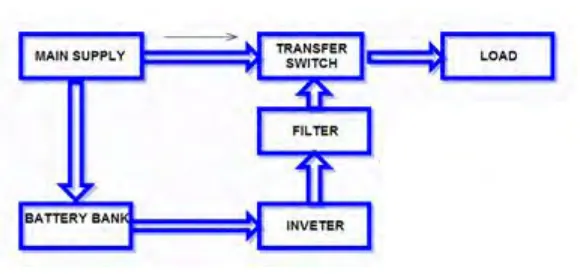
[image:23.612.168.458.185.322.2]2.3.1 Uninterruptible Power Supply
Figure 2.1: Block diagram
Uninterruptible Power Supply(UPS) is maintains a continuous supply of electric power to connected equipment by supplying power from a separate source when utility power is not available. It varies from an assistant power supply or standby generator, which does not give moment assurance from a transient power intrusion.
2.3.2 Elements of UPS
The elements of UPS had divided 6 elements which is: Input
Rectifier/battery charger Dc system
11
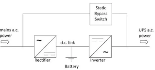
[image:24.612.197.500.177.314.2]2.3.3 The static bypass
Figure 2.2: simple block diagram of UPS
Figure2.2 shown the simple block diagram for online UPS. In case of a framework disappointment, the static sidestep consequently shuts the circuit and enables the approaching energy to occupy around the rectifier, batteries and the inverter to supply utility review control (unconditioned) straightforwardly to your heap. In spite of the fact that this isn't adapted power, it enables your frameworks to keep working regardless of whether the UPS's inside segments come up short.
[image:24.612.129.474.545.673.2]2.3.4 Rectifier