International Journal of Innovative Technology and Exploring Engineering (IJITEE) ISSN: 2278-3075, Volume-8, Issue- 6S4, April 2019
Abstract— Methods found in the literature are regularly not capable of concurrently examine financial and technical oriented benefits for multi-location DG placement systems. Therefore an effective system is presented to such benefits as for multiple DG placements. Particle Swarm Optimization (PSO) is extensively used to optimize dimensional data in number of applications due to its fast searching and converging property to optimal solution and hence used in finding optimal location for multi DG placement. It is tested on 33 IEEE bus systems in which three initial locations are selected on random basis for DG placement and power flow analysis is done to evaluate electricity losses and voltage profile at all buses. Then PSO is used to find the optimal locations which give high values of voltage profile then initial configuration and proposed three best effective, beneficial locations where there are minimum electricity losses and high voltage profile indices. For speedy convergence of the algorithm adaptive weight parameter is used instead of fixed weight. Experimental results have been carried out for IEEE 33 radial bus in which type-1 DG placement is considered. With optimized locations, new switch-ties gives 70.4 % less power loss than the initial tied switches.
Keywords: DG placement, 33 IEEE radial bus, Distributed generation, Optimal location, PSO, Newton-Raphson
I. INTRODUCTION
At central station generations, the electricity in majority is produced, and transferred over a transmission line which is of high-voltage range to distributed networks afore sourcing drives to customers in a outmoded strength approach. Nevertheless, in recent times, owing to reduction in budget of scales, technical invention, ecological and market place liberalization, DG units are all-pervading the power scheme in major numbers and capacity [1]. Moreover, by means of the minor level size like DG units setting up time and specific doubts in financial preparation and building are abridged. Consequently, the DG plans originate by way of a reduced amount of threat associated with fundamental power plants. Furthermore, modularizing the DG technologies, for instance fuel cell, could be set up in amounts to raise entire size to counterpart load escalation. DG units could provide improved feature of power to distributed network and there will be improvement in profile of the voltage closer to the cease of distributed feeder and diminish bottleneck and electricity losses within the networks, meanwhile they could openly stream electricity to the native request. Distributed generation improves
Revised Manuscript Received on April 12, 2019.
Nitin Khajuria, Department of Electrical Engineering, Chandigarh University, Mohali, India. ([email protected])
Satyanand Vishwakarma, Department of Electrical Engineering, Chandigarh University, Mohali, India. ([email protected])
Rohit Kumar, Department of Electrical Engineering, Chandigarh University, Mohali, India. ([email protected])
consistency with the aid of developing electricity supply in a particular sector, diminishes the electricity distribution and energy losses over Transmission & Distribution systems, and deferment the requirement of Transmission & Distribution exaltation through the use of nearby belongings [2]. There are many ways to maintain the operations, reliability, expenditure and performance of the distribution units which is generally named as reconfiguration of the network, placing distributed-generations (DG’s) and placing the capacitors etc. Those electrical power units which are positioned close to the load side and also makes a connection with the distribution networks are generally considered to be distributed generation. Depending on their power delivering capability, the DG units are categorized into 4 main types depending upon their capabilities of providing the active power and reactive power
Type-1: That supplies or gives the best active electricity or power at unity strength component of DG
Type-2: That supplies or gives the best reactive electricity or power at zero strength component of DG
Type-3: That supplies or gives the active power but by absorbing reactive electricity or power
Type-4: That supplies or gives reactive and active power at power factor which lies in b/w zero to 1
In [3], a logical expression is proposed for examining the optimum size and location of DG units for decreasing power loss beside procedures for recognizing the finest position. An analytical methodology is implemented in [4] for most excellent location of a set of Distributed generation unit so that loss in the power can be minimized. Therefore, a technique is suggested so that the location of Distributed Generation units can be identified so that load capacity will be increase in distribution system in [5]. The two methods plays a significant role to define location where Distributed generation could be placed and size which are generally, the algorithm of Genetic method and Particle optimization method so that we can be able to minimize the losses that is occurring in system in [6] and [7]. In [8], we are having multi goal index characteristic whose performance generally is minimized by using GA-based algorithm. When distributed generation takes place, then there will be an effect in active as well as reactive loss of the power scheme, due to this there will be loading of the line in the distribution and improvement
Multiple DG Placement in Radial Bus System
using Weight Adaptive Swarm Intelligence to
Improve Voltage Profile
in the profile of the voltage which is reflected by the keys. At every bus voltage is bound therefore GA is generally used to find the optimum location and size of Distributed generation units in order to lessen the damages that happened in system as well as the power which is supplied by the main grid, in [9]. A whole effect of a DG on voltage constancy is up owing to decline reactive power losses and enhanced voltage profiles. In [10], a systematic routine was analyzed to define the best size and the suitable location of the Distributed generation in order to minimize the line losses that is present in the power system. In [11], optimum size and location of a DG in a interconnected arrangement was recognized by an comprehensive exploration procedure, considering account scheme losses and short circuit levels. The Particle and swarm optimization method was presented so that we can classify Distributed generation unit location and its size by which we can diminish the actual power damages in [12] and [13]. [14] introduced the algorithm of adaptation in weight Particle swarm optimization in order to discover the optimal placements of various Distributed generation; though the impartial task was to somehow minimize the loss that is happening in the active power of the method. In [15], grouping of GAs and PSO was used to invent the most beneficial position of a restore functionality of Distributed generation units installed into the network. [16] Introduced method of Particle swarm optimization system so that losses can be minimized that is occurring at the active power in order to recognize numerous placements of the Distributed generation with power factor equal to non-unity. Then, PSO algorithm used in [17] for a multi-goal index-based method which is used to recognize optimum location, size of the Distributed unit in the distribution network through diverse representation of the load. Persistence energy streams in order to define the impact which is having on the Distributed generation units on maximum sensitive buses which results in the to collapse of the voltage.
II. VOLTAGE STABILITY
The stability in the voltage is generally defined as the capability of network, so that voltage level can be preserve among bounds in every bus in the scheme afterward being exposed to a trouble after an assumed preliminary process state. The uncertainty which is occurring in system voltage is due to the result of collapse of the voltage which associates many power system modules and their variables. This method would results a power failure or infrequent value of voltage which is of low size in a particular portion of power network. The Voltage constancy in the broadcasting or in the distributed network can also be considered by having a support of fixed load boundary which is generally a supplementary loading that scheme could endure above and beyond the base case load former to the collapse argument. Load ability is proportionate to the fixed loading boundary of the method and it could be contingent on load and peers commands [18], [19]. Amongst numerous practices to solve power flow equations, Newton-Raphson is an effective method when there is large size of bus system. Gauss –Seidal however converge faster when small bus system is under consideration.
III. PROPOSED METHODOLOGY
A. Problem Formulation
Main feature of this placement hassle to reduce the general losses that is occurring in the overall reactive power which is generally specified in (2), wherever the loss in reactive power formula is employed. Reduced objective function
1 1
(
)
(
)
N N
jk j k j k L
j k jk j k j k
P P
Q Q
Q
Q P
P Q
(2)Where jk jk
cos(
j k)
j k
x
V V
(2a)sin(
)
jk
jk j k
j k
x
V V
(2b)j j
V
is the voltage at the bus j and rjk +jxjk = Zjk isjkth element of Zbus. Subject to equality constraints
2
1
cos( )
N
gi mi i ii in i n in n i n
n i
P P V G Y V V
(3a)2
1
sin(
)
N
gi mi i ii in i n in n i
n n i
Q
Q
V B
Y V V
(3b)Where the voltage at the typical bus i.e the ith bus,
i i i
V
V
and| (cos sin )
ij ij ij ij ij ij ij ij
Y Y Y j G jB bus
admittance matrix element. Inequality constraint
min i max
1,...,
V
V
V
i
N
(4a)g min i gi g max i 1,...,
P P P i N (4b)
g min i gi g max i 1,...,
Q Q Q i N (4c)
IV. PARTICLE AND SWARM
OPTIMIZATION (PSO)
International Journal of Innovative Technology and Exploring Engineering (IJITEE) ISSN: 2278-3075, Volume-8, Issue- 6S4, April 2019
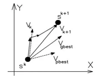
Fig. 1: Movement of searching-point in PSO
Let us consider that v and i are generally the velocity and position of a particle which is loacated in the search space, respectively. Consequently, this ith particle is provided as si = (si1, si2,…, sid) where the d is dimensional space. The greatest former point of the ith particle is verified and presented as pbesti = (pbesti1, pbesti2, . . . , pbestid ). The
best particle amongst the particles in the group is conferred by gbestid. The velocity for particle i is given as vi = (vi1,
vi2, . . . , vid ). The current position and velocity of each particle could be computed with current and previous velocity, and the particle which is at preceding position, as shown in fig 1.
1
1
2
*
* rand() *(pbest
v )
c *
() *(gbest
v )
k k k
id id id id
k d id
v
v
c
rand
(5)1 1
,
1, 2,..., n, d 1, 2,..., m
k k k id id id
s s v
i
(6)
where
m quantity of individuals in the particle; n quantity of particles in the group; ω inertia weight factor;
k iteration kth;
c1, c2 acceleration constants;
rand() uniform random value in the range ;
υk i denotes the velocity of the particle i at k iteration; sk I denotes the position of the particle i at k iteration. Appropriate choice of inertia weight ω offers stability among local and global examinations, therefore demanding smaller amount iteration, on average, to analyze an adequately optimum result. So by using the formula which is given below, inertia weight specific function can be calulated
max min
max
max
k
k
(7)where ωmax and ωmin denotes maximum and minimum
inertia weight, correspondingly. The standards of ωmin and
ωmax are 0.4 and 0.9, correspondingly. The c1 and c2
denotes the constant of the acceleration and are generally considered to be 2.0. In Figure 1, sk+1 they are generally searching point which are modified, sk is the current searching point, vk+1 is the velocity of agent I which is modified, vk denotes the current velocity, Vgbest is the velocity which is generally based on gbest and Vpbest is thew velocity based on pbest.
A. Partial swarm optimization Procedure
To reduce the loss in reactive power an approach or method is introduced to discover the size and location of Distributed generation units which is generally termed as Particle and swarm optimization method and it involves the following stages.
1. Enter bus voltage limits and system data (bus and line information).
2. Compute the base case loss of reactive power through the load flow of the distribution.
3. Arbitrarily produce primary inhabitants of particles by arbitrary velocities and positions on the dimensions. Fixed the iterative k count which is equivalent to 0.
4. For each particles assume if the bus voltage is specified in limits, then we can compute the overall loss in reactive power by (2). If not, then of course that particle is assume to be infeasible.
5. For all particles, differentiate its value of objective with that of the specific best. If the value of objective is lesser than that of the pbest, assign this value as per that of current pbest, so that we can account for the matching position of particle. 6. Choose a particle related to that of least individual,
best value of the pbest from all the particles, thereby assigning the pbest value in place of current total best value of gbest.
7. Update its position and the velocity of the particles by considering 5 and 6.
8. If our iteration having a number that will reach to its highest value, then move to Step 9. Else, assign index for iteration which is k = k +1, then move to step four.
9. At the end try to display the optimum answer of objective problem and finest location comprises the optimum size, location of Distributed generation and their corresponding value of the fitness expressing the minimum total loss in the active power.
V. RESULTS AND DISCUSSIONS
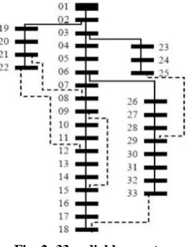
Fig. 2: 33 radial bus system
With the aid of installing Distributed generation units inside the system, each real and reactive electricity losses are diminished and therefore the load factor is enriched expressively. Nonlinear and differential equations are generally solved by using the method of Newton and Raphson. Therefore the desired results of real power index performance indices for the base case loading condition is given in Table 1. The DGs are first put at buses five, sixteen and nineteen and optimal locations are evaluated.
TABLE 1: CHANGE IN ACTIVE POWER LOSS, MINIMUM VOLTAGE PROFILE AND AVERAGE
VOLTAGE PROFILE WITH AND WITHOUT OPTIMIZATION
Parameters Initial configuration
DG placement using PSO Loss in Overall
Power 438.662 kW 124.6337 kW
Minimum Voltage
Profile found 0.8294 pu 0.95295 pu
Average voltage
[image:4.595.311.543.64.675.2]profile 0.8865 pu 0.9710 pu
Fig. 3: Voltage profile comparison
TABLE 2: VOLTAGE PROFILE WITH INITIAL CONFIGURATION AND FINAL CONFIGURATION
FOUND BY PSO Bus
number
Voltage Profile with initial configuration
Voltage Profile using APSO
1 1 1
2 0.996827 0.997081
3 0.980672 0.986669
4 0.980124 0.983195
5 0.979941 0.979957
6 0.861072 0.974551
7 0.856739 0.973915
8 0.839623 0.964942
9 0.834479 0.962275
10 0.831964 0.963941
11 0.831639 0.964025
12 0.831174 0.96432
13 0.829634 0.961742
14 0.829404 0.96095
15 0.83002 0.957292
16 0.829601 0.956036
17 0.880637 0.953579
18 0.88103 0.953021
19 0.996696 0.995178
20 0.832599 0.979277
21 0.833019 0.974844
22 0.831929 0.971388
23 0.965715 0.981298
24 0.93528 0.970802
25 0.90846 0.963683
26 0.863424 0.973341
27 0.866866 0.97178
28 0.882168 0.965566
29 0.894202 0.961269
30 0.889862 0.957717
31 0.884092 0.953831
32 0.882656 0.953032
33 0.881773 0.952953
[image:4.595.46.291.422.709.2]International Journal of Innovative Technology and Exploring Engineering (IJITEE) ISSN: 2278-3075, Volume-8, Issue- 6S4, April 2019
Three DG units of equal size are chosen for placement and with initial configuration total power losses are equal to 420.508 KW which is evaluated for 33 bus radial bus system which results from system losses at variant load-levels. Similar losses are evaluated when optimized locations found by PSO which are 124.6337 KW and approx. 70% less than initial configuration. PSO is also tested with fixed weight and adaptive weight where adaptive weight based PSO converges faster to optimal solution.
VI. CONCLUSION
The optimal allocation of the DG with swarm optimization is carried out in this work. Results show proficiency of the PSO based DG placement for reducing of power losses , voltage profile improvement then initial randomly chosen configurations, , economically beneficial and enhancing reliability of the system. Testing of implemented method is carried out on DG’s that operates at unity power factor named as type-1. The presented PSO method gives better results for the tested 33 IEEE radial bus system. Three locations are chosen as initial configuration which is at fifth, sixteenth and nineteenth bus that are shown here in result section. The optimal locations found are seventh, ninth and fourteenth which are produced whatever initial locations are provided. It can be concluded that there is efficient reduction in both real and reactive power-losses along with improvements in voltage profile. PSO has been improved in many applications in which especially evolution of weight parameter is proposed, hence PSO variants can be used for fast convergence as a part of future scope.
REFERENCES
1. Chandrasekhar Yammani, Sydulu Maheswarapu,
Sailajakumari Matam “Multiobjective Optimization for Optimal Placement and Size of DG using Shuffled Frog Leaping Algorithm”, Energy Procedia, Volume 14, 2012, Pages 990-995
2. Oscar Andrew Zongo, Anant Oonsivilai “Optimal placement
of distributed generator for power loss minimization and voltage stability improvement”, Energy Procedia, Volume 138, 2017, Pages 134-139
3. M.M. Aman, G.B. Jasmon, A.H.A. Bakar, H. Mokhlis “A new
approach for optimum DG placement and sizing based on voltage stability maximization and minimization of power losses”, Energy Conversion and Management, Volume 70, 2013, Pages 202-210
4. Hasan Doagou-Mojarrad, G.B. Gharehpetian, H. Rastegar,
Javad Olamaei “Optimal placement and sizing of DG (distributed generation) units in distribution networks by novel hybrid evolutionary algorithm’’, Energy, Volume 54, 2013, Pages 129-138
5. Bikash Das, V. Mukherjee, Debapriya Das “Optimum DG
placement for known power injection from utility/substation by a novel zero bus load flow approach”, Energy, Volume 175, 2019, Pages 228-249
6. Miguel A. Velasquez, Nicanor Quijano, Angela I. Cadena
“Optimal placement of switches on DG enhanced feeders with short circuit constraints”, Electric Power Systems Research, Volume 141, 2016, Pages 221-232
7. Paschalis A. Gkaidatzis, Aggelos S. Bouhouras, Dimitrios I.
Doukas, Kallisthenis I. Sgouras, Dimitris P. Labridis “Load variations impact on optimal DG placement problem concerning energy loss reduction”, Electric Power Systems Research, Volume 152, 2017, Pages 36-47
8. Ashokkumar Lakum, Vasundhara Mahajan “Optimal
placement and sizing of multiple active power filters in radial distribution system using grey wolf optimizer in presence of nonlinear distributed generation”, Electric Power Systems Research, Volume 173, 2019, Pages 281-290
9. Ehsan kianmehr, Saman Nikkhah, Abbas Rabiee
“Multi-objective stochastic model for joint optimal allocation of DG units and network reconfiguration from DG owner’s and DisCo’s perspectives”, Renewable Energy, Volume 132, 2019, Pages 471-485
10. D.B. Prakash, C. Lakshminarayana “Multiple DG placements
in radial distribution system for multi objectives using Whale Optimization Algorithm”, Alexandria Engineering Journal, Volume 57, Issue 4, 2018, Pages 2797-2806
11. Sajjan Kumar, Kamal K. Mandal, Niladri Chakraborty
“Optimal DG placement by multi-objective opposition based chaotic differential evolution for techno-economic analysis”, Applied Soft Computing, Volume 78, 2019, Pages 70-83
12. P. Vijay Babu, S.P. Singh “Optimal Placement of DG in
Distribution Network for Power Loss Minimization Using NLP & PLS Technique”, Energy Procedia, Volume 90, 2016, Pages 441-454
13. Subhrajyoti Sahu, Ajit Kumar Barisal, Abhishek Kaudi
“Multi-objective optimal power flow with DG placement using TLBO and MIPSO: A comparative study”, Energy Procedia, Volume 117, 2017, Pages 236-243
14. Pathomthat Chiradeja, Suntiti Yoomak, Atthapol
Ngaopitakkul“Optimal Allocation of Multi-DG on
Distribution System Reliability and Power Losses Using Differential Evolution Algorithm”, Energy Procedia, Volume 141, 2017, Pages 512-516
15. Surajit Sannigrahi, Parimal Acharjee “Maximization of
System Benefits with the Optimal Placement of DG and DSTATCOM Considering Load Variations”, Procedia Computer Science, Volume 143, 2018, Pages 694-701
16. D. Rama Prabha, T. Jayabarathi “Optimal placement and
sizing of multiple distributed generating units in distribution networks by invasive weed optimization algorithm”, Ain Shams Engineering Journal, Volume 7, Issue 2, 2016, Pages 683-694
17. S.A. ChithraDevi, L. Lakshminarasimman, R. Balamurugan
“Stud Krill herd Algorithm for multiple DG placement and sizing in a radial distribution system”, Engineering Science and Technology, an International Journal, Volume 20, Issue 2, 2017, Pages 748-759
18. Dinakara Prasad Reddy P., Veera Reddy V.C., Gowri
Manohar T. “Optimal renewable resources placement in distribution networks by combined power loss index and whale optimization algorithms”, Journal of Electrical Systems and Information Technology, Volume 5, Issue 2, 2018, Pages 175-191
19. Bindeshwar Singh, Deependra Kumar Mishra “A survey on
enhancement of power system performances by optimally placed DG in distribution networks”, Energy Reports, Volume 4, 2018, Pages 129-158
AUTHORS PROFILE
Satya Vishwakarma. He is working as Assistant professor in Electrical Engineering department in Chandigarh University, Punjab. He did his M.TECH in Power Systems Engineering in Galgotias University Noida. He is having wide area of interest in the field of Electric vehicles and Renewable generation.