Simo, Jules and McInnes, Colin (2012) Feedback stabilization of
displaced periodic orbits : Application to binary asteroid. In: 22nd
AAS/AIAA Spaceflight Mechanics Meeting, 2012-01-29 - 2012-02-02. ,
This version is available at https://strathprints.strath.ac.uk/36808/
Strathprints is designed to allow users to access the research output of the University of Strathclyde. Unless otherwise explicitly stated on the manuscript, Copyright © and Moral Rights for the papers on this site are retained by the individual authors and/or other copyright owners. Please check the manuscript for details of any other licences that may have been applied. You may not engage in further distribution of the material for any profitmaking activities or any commercial gain. You may freely distribute both the url (https://strathprints.strath.ac.uk/) and the content of this paper for research or private study, educational, or not-for-profit purposes without prior permission or charge.
Any correspondence concerning this service should be sent to the Strathprints administrator: [email protected]
AAS 12-130
FEEDBACK STABILIZATION OF DISPLACED PERIODIC ORBITS:
APPLICATION TO BINARY ASTEROID
Jules Simo∗and Colin R. McInnes†
This paper investigates displaced periodic orbits at linear order in the circular re-stricted Earth-Moon system (CRTBP), where the third massless body utilizes a hybrid of solar sail and a solar electric propulsion (SEP). A feedback linearization control scheme is implemented to perform stabilization and trajectory tracking for the nonlinear system. Attention is now directed to binary asteroid systems as an application of the restricted problem. The idea of combining a solar sail with an SEP auxiliary system to obtain a hybrid sail system is important especially due to the challenges of performing complex trajectories.
INTRODUCTION
The design of spacecraft trajectories is a crucial task in space mission design. However, propel-lant usage is a critical parameter for any spacecraft mission, thus the choice of an efficient control strategy is important. Propellantless spacecraft propulsion systems such as solar sailing rely on solar radiation pressure, the flux of momentum transported by sunlight, to provide propulsive force. A so-lar sail is then a so-large, flat, lightweight reflective surface deployed in space that can propel spacecraft without the use of propellant. Although the force on a solar sail spacecraft is less than a conventional chemical rocket, the solar sail spacecraft constantly accelerates over time and achieves a significant energy change. Therefore, this form of propulsion can in principle provide energy changes greater than are possible with either ion or chemical propellants. This paper covers the results of a study on displaced periodic orbits in the Earth-Moon system in which the third body uses a hybrid solar sail. The hybrid sail model is composed of two low thrust propulsion systems, namely a solar sail and solar electric propulsion. In a prior study, displaced lunar orbits was investigated using low-thrust propulsion.1, 2, 3, 4, 5, 6, 7 The idea of combining a solar sail with an auxiliary SEP system to obtain a hybrid sail system is important due to the challenges of performing complex missions.8, 9, 10 The
solar electric propulsion system possesses high specific impulse (Isp ≈3000sec). SEP consumes
propellant and decreases the mass of the spacecraft, whereas the solar sail does not consume any propellant. This form of propulsion is useful for some high energy missions, but unlike solar sails, they have a finite∆V capability, which makes them unsuitable for missions where a non-Keplerian orbit has to be maintained over indefinite periods of time.
Solar sails can also be utilised to maintain highly non-Keplerian orbits, such as closed orbits displaced high above the ecliptic plane. Solar sails are especially suited for such non-Keplerian orbits,11, 12, 13, 14, 15 since they can apply a propulsive force continuously over long periods. In such trajectories, a sail can be used as a communication satellite for high latitudes. For example, the orbital plane of the sail can be displaced above the orbital plane of the Earth, so that the sail can
∗
Academic Visitor, Department of Mechanical and Aerospace Engineering, University of Strathclyde, Glasgow, G1 1XJ, United Kingdom. Email: [email protected].
†
stay fixed above the Earth at some distance, if the orbital periods are equal. Displaced orbits have more recently been developed using collocation schemes and Finite-difference methods.16, 17 A new concept of creating artificial equilibria aboveL1point in the Sun-Earth system for Earth observation
has been proposed, in which the third body uses a hybrid of solar sail and SEP. These artificial equi-libria have potential applications for future space physics and Earth observation missions. Hybrid low-thrust propulsion has been proposed on the same spacecraft to enable a pole-sitter orbit.18 Dis-placed geostationary orbits using hybrid low-thrust propulsion has also been proposed to increase the capacity of the geostationary ring.19 In fact, the pressure from sunlight reflecting off the solar sail pushes the satellite above or below geostationary orbit, and also displaces the centre of the orbit behind the Earth, away from the Sun.
The Earth-Moon libration points have been a topic of great interest in recent years. Particularly attractive are the orbits around the collinear points because their unique positions are advantageous for several important applications in space mission design.20, 21, 22, 23, 24, 25, 26 Such orbits cannot be maintained without active control due to their instability.24, 25, 26If the orbit maintains visibility from
Earth, a spacecraft on it (near the L2 point) can be used to provide communications between the
equatorial regions of the Earth and the lunar poles. Moreover, if another communications satellite is located at theL1point, there could be continuous communications coverage between the equatorial
region of the Earth and the entire lunar surface.
This paper investigates displaced periodic orbits at linear order in the circular restricted Earth-Moon system, where the third massless body utilizes a hybrid of solar sail and a solar electric propulsion system. In particular, periodic orbits in the vicinity of the Lagrange points in the Earth-Moon system will be explored along with their applications. Firstly we describe the dynamic model of the hybrid sail. The first-order approximation is derived for the linearized equations of motion. Then, a feedback linearization control scheme27is proposed and implemented. The main idea of this approach is to cancel the nonlinearities and to impose desired linear dynamics satisfied by the solar sail. We then select the SEP control, which takes into consideration the nonlinearity cancellation and the stabilizing linear control. When the control is applied to the nonlinear system, asymtotic stability is achieved. This provides the key advantage that the displacement distance of the hybrid sail is then constant. A hybrid concept for displaced periodic orbits in the Earth-Moon system has been developed. In recent years a significant progress has been made in discovery of binary asteroids among all populations in the solar system.28 The binary near-Earth asteroids (NEAs) have been
discovered from a combination of lightcurve and radar observations. Near-Earth Objects include asteroids and comets whose orbits approach or intersect the Earths orbit around the Sun.29, 30, 31 A natural extension of the hybrid concept is then to investigate the possible transition to a binary system. Finally, this research integrates results from the dynamics in order to develop a mission to a binary asteroid system. Therefore, important generalizations of the physical nature of the primaries lead to modified versions of the restricted problem, in which the primaries have either variable or equal masses. The displaced orbits found in the reference16show large excursions in displacement distance. In practice, a constant displacement distance may lead to easier tracking from the lunar surface for communications applications. Finally, we evaluate the performance of the hybrid sail approach.
SYSTEM MODEL
In this work m1 represents the larger primary (Earth),m2 the smaller primary (Moon) and we
x Moon
Sun−line
z
ξ L2
η ζ
Sail
γ n m
r2
r1
x
m1= 1−µ m2=µ
ω
y
S
µ 1−µ
Earth
(a)
SEP Thruster Sail
m
n
γ
S
[image:4.612.107.534.53.261.2](b)
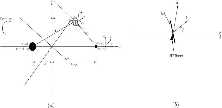
Figure 1 (a) Schematic geometry of the Hybrid Sail in the Earth-Moon circular
restricted three-body problem;(b)Angleγbetween the Hybrid Sail surface normaln
and the Sun-line directionS, and SEP thrust vector directionm.
the two more massive bodies are moving in circular orbits with constant angular velocityω about their common center of mass, and the mass of the third body is too small to affect the motion of the two more massive bodies. The unit mass is taken to be the total mass of the system(m1+m2)and
the unit of length is chosen to be the constant separationR⋆betweenm
1andm2. The time unit is
defined such thatm2 orbits aroundm1 in time2π. Under these considerations the masses of the
primaries in the normalized system of units arem1= 1−µandm2=µ, withµ=m2/(m1+m2)
(see Figure 1 (a)). The dashed line in Figure 1 (a)) is a line parallel to the Sun-line direction.
Equations of Motions
The nondimensional equation of a motion of a hybrid sail in the rotating frame of reference is described by
d2r
dt2 + 2ω×
dr
dt +∇U(r) =aS+aSEP, (1)
whereω = ωˆz (ˆzis a unit vector pointing in the directionz) is the angular velocity vector of the rotating frame andris the position vector of the hybrid sail relative to the center of mass of the two primaries. We will not consider the small annual changes in the inclination of the Sun-line with respect to the plane of the system. The three-body gravitational potentialU(r), the solar radiation pressure acceleration aS and the nondimensional acceleration due to the SEP thruster aSEP are defined by
U(r) = −
"
1 2|ω×r|
2+1−µ
r1
+ µ
r2
#
,
aS = a0(S·n)2n, (2)
where µ = 0.012150582is the mass ratio for the Earth-Moon system. The hybrid sail position vectors w.r.t. m1 andm2 respectively (see Figure 1 (a)), are defined as r1 = [x+µ, y, z ]T and
r2 = [x−(1−µ), y, z]T, a
0 is the magnitude of the solar radition pressure acceleration exerted on
the hybrid sail and the unit vectorndenotes the thrust direction,aSEP is the acceleration from the SEP system and the unit vectormdenotes the thrust direction. A constant displacement distance of 1750kmhas been imposed, considering a characteristic acceleration ofa0 = 0.10mm/s2for the
simulations. The sail is oriented such that it is always directed along the Sun-lineS, pitched at an angleγ to provide a constant out-of-plane force. The unit normal to the hybrid sail surfacenand the Sun-line direction are given by
n =
cos(γ) cos(ω⋆t) −cos(γ) sin(ω⋆t) sin(γ)
T
,
S =
cos(ω⋆t) −sin(ω⋆t) 0
T
,
whereω⋆ = 0.923is the angular rate of the Sun-line in the corotating frame in a dimensionless
synodic coordinate system.
Linearized System
We now want to investigate the dynamics of the hybrid sail in the neighborhood of the libra-tion points. We denote the coordinates of the equilibrium point as rL = (xLi, yLi, zLi) with
i = 1,· · · ,5. Let a small displacement in rL be δr such that r → rL +δr. The equations for
the hybrid sail can then be written as
d2δr
dt2 + 2ω×
dδr
dt +∇U(rL+δr) =aS(rL+δr) +aSEP(rL+δr), (4)
and retaining only the first-order term inδr = [δx, δy, δy]T in a Taylor-series expansion, the
gradi-ent of the potgradi-ential and the acceleration can be expressed as
∇U(rL+δr) = ∇U(rL) +∂∇U(r)
∂r r
=rL
δr+O(δr2), (5)
aS(rL+δr) = aS(rL) + ∂aS(r)
∂r r
=rL
δr+O(δr2), (6)
aSEP(rL+δr) = aSEP(rL) +∂aSEP(r)
∂r r
=rL
δr+O(δr2). (7)
It is assumed that∇U(rL) = 0, and the accelerationsaS andaSEP are constant with respect to
the small displacementδr, so that
∂aS(r) ∂r
r
=rL
= 0, (8)
∂aSEP(r)
∂r r
=rL
= 0. (9)
The linear variational system associated with the libration points atrLcan be determined through a Taylor series expansion by substituting Eqs. (5), (6) and (7) into (4) so that
d2δr
dt2 + 2ω×
dδr
where the matrixKis defined as
K =−
"
∂∇U(r) ∂r
r
=rL
#
. (11)
Using matrix notation the linearized equation about the libration point (Equation (10)) can be repre-sented by the inhomogeneous linear systemX˙ =AX+b(t), where the state vectorX= (δr, δr˙)T,
and for whichb(t) (a6×1vector) is equal to the sum of control accelerations of the sail and the SEP.
The Jacobian matrixAhas the general form
A=
03 I3
K Ω
, (12)
whereI3is a identity matrix, and
Ω =
0 2 0
−2 0 0 0 0 0
. (13)
By making the transformation r → rL +δr and retaining only the first-order term in δr =
(ξ, η, ζ)T in a Taylor-series expansion where (ξ, η, ζ) are axes attached to the libration point as
shown in Figure 1 (a), the linearized nondimensional equations of motion relative to the collinear libration points can be written as
¨
ξ−2 ˙η−Uxxo ξ = aξ+aSEPξ, (14)
¨
η+ 2 ˙ξ−Uyyo η = aη +aSEPη, (15)
¨
ζ−Uzzo ζ = aζ+aSEPζ, (16)
whereUo
xx, Uyyo ,andUzzo are the partial derivatives of the gravitational potential evaluated at the
collinear libration point, and the solar sail acceleration is defined in terms of three auxiliary variables
aξ,aη, andaζ.
Again, the sail attitude is fixed such that the sail normal vectorn, which is the unit vector that is perpendicular to the sail surface, points always along the direction of the Sun line with the following constraintS·n ≥0. Its direction is described by the pitch angleγ relative to the Sun-line, which represents the sail attitude.
The solar sail acceleration components are therefore given by
aξ = a0cos(ω⋆t) cos3(γ), (17)
aη = −a0sin(ω⋆t) cos3(γ), (18)
aζ = a0cos2(γ) sin(γ), (19)
wherea0 is the characteristic acceleration. The SEP acceleration components aSEP are used for
TRACKING BY FEEDBACK LINEARIZATION
Linearization by feedback is a well-known approach to control nonlinear systems. This method transforms a nonlinear state space model into a new coordinate system where the nonlinearities can be cancelled by feedback. It is a way of transforming system models into equivalent models of simpler form.
This technique is completely different from a Jacobian linearization, on which linear control is based. From equation (1) the motion of the hybrid solar sail in the CRTBP is described by the scalar equations in the form
¨
ξ = 2 ˙η+ (xL2+ξ)−(1−µ)
(xL2 +ξ) +µ
r13 −µ
(xL2+ξ)−1 +µ
r23 +aξ+uξ, (20)
¨
η = −2 ˙ξ+η− 1−µ
r31 + µ r32
!
η+aη +uη, (21)
¨
ζ = − 1−µ
r31 + µ r32
!
ζ+aζ+uζ, (22)
where the vector
u(t) = uξ uη uζ T (23)
is the applied control acceleration due to the SEP thruster, such thatu(t),aSEP.
To develop a feedback linearization scheme, the motion of the hybrid solar sail moving in the CRTBP is separated into linear and nonlinear components, such that
¨
ξ = fN onξ −Linear+fLinearξ +aξ+uξ, (24)
¨
η = fN onη −Linear+fLinearη +aη+uη, (25)
¨
ζ = fN onζ −Linear+fLinearζ +aζ+uζ, (26)
where thef functions are defined as the linear and the nonlinear terms in the equations (20), (21) and (22)
fN onξ −Linear = −(1−µ)(xL2 +ξ) +µ
r13 −µ
(xL2 +ξ)−1 +µ
r23 , (27)
fLinearξ = 2 ˙η+ (xL2+ξ), (28)
fN onη −Linear = − 1−µ
r3 1
+ µ
r3 2
!
η, (29)
fLinearη = −2 ˙ξ+η, (30)
fN onζ −Linear = − 1−µ
r3 1
+ µ
r3 2
!
ζ, (31)
fLinearζ = 0, (32)
withr1 =
p
((xL2 +ξ) +µ)2+η2+ζ2 and r2 = p
((xL2+ξ)−1 +µ)2+η2+ζ2.
u(t) = uξ uη uζ
= U(t) +u˜(t), (33)
where
U(t) =−
(xL2 +ξ)−(1−µ)
(xL2+ξ)+µ
r3 1
−µ(xL2+ξ)−1+µ
r3 2
−Uo
xxξ
− 1r−3µ 1
+rµ3 2
!
η−Uo
yyη
− 1−r3µ 1
+rµ3 2
!
ζ−Uo
zzζ . (34)
The equations (20), (21) and (22) then become
¨
ξ = 2 ˙η+Uxxo ξ+a0cos(ω⋆t) cos3(γ) + ˜uξ, (35)
¨
η = −2 ˙ξ+Uyyo η−a0sin(ω⋆t) cos3(γ) + ˜uη, (36)
¨
ζ = Uo
zzζ+a0cos2(γ) sin(γ) + ˜uζ. (37)
By removing the nonlinear dynamics from the system, the control acceleration vector u˜(t) is
determined such that the desired response characteristics of the linear time-invariant dynamics are produced and so Eq. (35) - (37) are identical to the linear system defined by Eq. (14) - (16). In particular, it can be ensured that the displacement distance of the periodic orbit is constant, which provides key advantages for lunar polar telecommunications.
TRACKING A REFERENCE TRAJECTORY Linear Feedback Control
Let us consider nonlinear system described by
¨
x=f(x,x˙) +u, (38)
where x ∈ R3 is the state. Let e(t) = x(t) −xref(t) denote the state error relative to some
reference solution, where the reference trajectory
xref(t) = ξref ηref ζref T (39)
is given by the analytical solution
ξref(t) = ξ0cos(ω⋆t), (40)
ηref(t) = η0sin(ω⋆t), (41)
ζref(t) = ζ0, (42)
We then differentiatee(t)until the control appears so that
e(t) = x(t)−xref(t), (43)
˙
e(t) = x˙(t)−x˙ref(t), (44)
¨
e(t) = x¨(t)−x¨ref(t), (45)
= f(x,x˙) +u−x¨ref(t), (46)
= −λ1e˙−λ2e, (47)
and so, we have
u(t) =−f(x,x˙) +x¨ref(t)−λ1e˙−λ2e, (48)
where−λ1e˙−λ2eis the stabilizing term.
Trajectory Tracking
Consider the system given by (38), where our objective is to make the output x ∈ R3 track a
desired trajectory given by the reference trajectoryxref ∈R3while keeping the position bounded.
Therefore, we want to find a control law for the inputu˜ ∈ R3 such that, starting from any initial
state in a domainD⊂R3, the tracking errore(t) =x(t)−xref(t)goes to zero.
Hence, asymptotic tracking will be achieved if we design a state feedback control law to ensure thate(t)is bounded and converges to zero asttends to infinity.
Thus, the control law
˜
u=−λ1e˙−λ2e (49)
yields the tracking error equation
¨
e+λ1e˙+λ2e= 0, (50)
whereλ1andλ2are chosen positive constants.
EVALUATION OF HYBRID SAIL PERFORMANCE
In this section we investigate the performance of the hybrid sail system, constituted by a solar sail combined with solar electric propulsion. The simulation was performed around the collinear libration point L2 for a period of one month. The magnitude of the total control effort appears
in Figure 4. Thus, the control acceleration effortU(t) required to track the reference orbit while rejecting the nonlinearities varies up to 0.005 (0.014 mm/s2) about the L2 point. The control
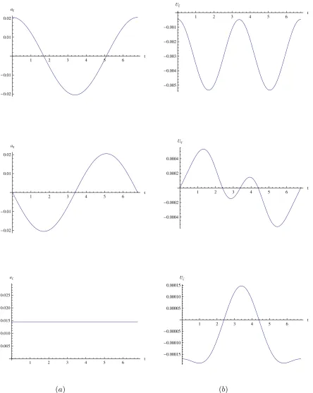
accelerations are continous smooth signals. The acceleration derived from the solar sail (denoted byaξ,aη,aζ) is plotted in terms of components for one-month orbits in Figure 2 (a) aboutL2, and
the SEP acceleration components appears in Figure 2 (b) aboutL2. The control acceleration effort
derived from the thruster (denoted byUξ,Uη, Uζ) is order of10−3 -10−4, while the acceleration
derived from the solar sail is approximately 10−2. The small control acceleration from the SEP
thruster is then applied to ensure that the displacement of the periodic orbit is constant. The solar sail provides a constant out-of-plane force.
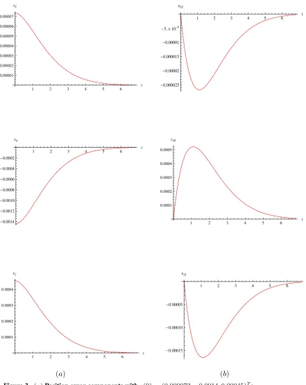
Figure 3 (a) (resp. Figure 3 (b)) illustrates the position error components, denoted byeξ, eη, eζ
(resp. velocity error components, denoted byeξd, eηd, eζd) under the nonlinear control and the SEP
thruster aroundL2. These Figures show that the motion is bounded and periodic. This observation
1 2 3 4 5 6 t
-0.02 -0.01 0.01 0.02
a
Ξ
1 2 3 4 5 6 t
-0.005 -0.004 -0.003 -0.002 -0.001
U
Ξ
1 2 3 4 5 6 t
-0.02 -0.01 0.01 0.02
aΗ
1 2 3 4 5 6 t
-0.0004 -0.0002 0.0002 0.0004
UΗ
1 2 3 4 5 6 t
0.005 0.010 0.015 0.020 0.025 a
Ζ
(a)
1 2 3 4 5 6 t
-0.00015 -0.00010 -0.00005 0.00005 0.00010 0.00015
UΖ
[image:10.612.120.564.70.627.2](b)
Figure 2 (a)Acceleration derived from the solar sail about theL2point;(b)
1 2 3 4 5 6
t
0.00001 0.00002 0.00003 0.00004 0.00005 0.00006 0.00007
eΞ
1 2 3 4 5 6
t
-0.000025 -0.00002 -0.000015 -0.00001 -5.´10-6
eΞd
1 2 3 4 5 6
t
-0.0014 -0.0012 -0.0010 -0.0008 -0.0006 -0.0004 -0.0002
e
Η
1 2 3 4 5 6
t 0.0001
0.0002 0.0003 0.0004 0.0005 e Ηd
1 2 3 4 5 6
t 0.0001
0.0002 0.0003 0.0004 eΖ
(a)
1 2 3 4 5 6
t
-0.00015 -0.00010 -0.00005
eΖd
[image:11.612.121.562.75.630.2](b)
Figure 3 (a)Position error components withe(0) = (0.000073,−0.0014,0.00045)T ;
1 2 3 4 5 6 t 0.001
[image:12.612.201.409.52.179.2]0.002 0.003 0.004 0.005 U
Figure 4. Magnitude of the total control effort about theL2point.
0.2 0.4 0.6 0.8 1.0 t
@daysD 0.0001
0.0002 0.0003 0.0004
U@mms2D
(a)
0.2 0.4 0.6 0.8 1.0 1.2 1.4t @daysD 0.0001
0.0002 0.0003 0.0004
U@mms2D
(b)
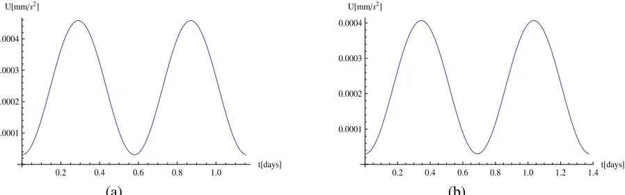
Figure 5 (a) Magnitude of the total control effort,µ = 0.25; (b) Magnitude of the
total control effort,µ= 0.5.
APPLICATIONS TO BINARY ASTEROID SYSTEMS
The previous section established a hybrid concept for displaced lunar orbits, using the Earth-Moon System as the primaries in the circular restricted three-body problem. The application to be treated here is related to binary asteroid systems. Thus, several set of curves of the control acceleration effort required to track a reference orbit while rejecting the nonlinearities are shown fromµ= 0.15toµ= 0.5.
The magnitude of the total control effort appears in Figure 5 (a) for system mass ratioµ= 0.25, and Figure 5 (b) forµ = 0.5. The control acceleration effortU(t)required to track the reference orbit while rejecting the nonlinearities varies up to 0.0004 mm/s2 for µ = 0.25 and µ = 0.5.
Again, the control accelerations are continous smooth signals. The acceleration derived from the solar sail (denoted byaξ,aη,aζ) is plotted in terms of components for one revolution of the asteroid
orbit in Figure 6 (a), and the SEP acceleration components appears in Figure 6 (b) for system mass ratio µ = 0.25. Similarly, the acceleration derived from the solar sail is plotted in terms of components for one revolution of the asteroid orbit in Figure 7 (a), and the SEP acceleration components appears in Figure 7 (b) for system mass ratioµ= 0.5. The control acceleration effort derived from the thruster (denoted byUξ,Uη, Uζ) is order of10−4 -10−5, while the acceleration
derived from the solar sail is approximately10−2forµ= 0.25andµ= 0.5.
[image:12.612.103.552.223.363.2]0.2 0.4 0.6 0.8 1.0 t
@daysD
-0.015
-0.010
-0.005 0.005 0.010 0.015
aΞ@mms2D
0.2 0.4 0.6 0.8 1.0
t@daysD
-0.0004
-0.0003
-0.0002
-0.0001 UΞ@mms2D
0.2 0.4 0.6 0.8 1.0 t@daysD
-0.015
-0.010
-0.005 0.005 0.010 0.015
aΗ@mms2D
0.2 0.4 0.6 0.8 1.0 t@daysD
-0.00004
-0.00002 0.00002 0.00004
UΗ@mms2D
0.2 0.4 0.6 0.8 1.0
t@daysD 0.005
0.010 0.015 0.020
aΖ@mms2D
(a)
0.2 0.4 0.6 0.8 1.0 t@daysD
-0.00002
-0.00001 0.00001 0.00002
UΖ@mms2D
[image:14.612.118.560.77.611.2](b)
Figure 6 (a)Acceleration derived from the solar sail with the system mass ratio
0.2 0.4 0.6 0.8 1.0 1.2 1.4t
@daysD
-0.015
-0.010
-0.005 0.005 0.010 0.015
aΞ@mms2D
0.2 0.4 0.6 0.8 1.0 1.2 1.4
t@daysD
-0.0004
-0.0003
-0.0002
-0.0001 UΞ@mms2D
0.2 0.4 0.6 0.8 1.0 1.2 1.4t@daysD
-0.015
-0.010
-0.005 0.005 0.010 0.015
aΗ@mms2D
0.2 0.4 0.6 0.8 1.0 1.2 1.4t@daysD
-0.000015
-0.00001
-5.´10-6 5.´10-6 0.00001 0.000015
UΗ@mms2D
0.2 0.4 0.6 0.8 1.0 1.2 1.4 t@daysD 0.005
0.010 0.015 0.020
aΖ@mms2D
(a)
0.2 0.4 0.6 0.8 1.0 1.2 1.4
t@daysD
-0.00001
-5.´10-6 5.´10-6
UΖ@mms2D
[image:15.612.116.563.74.612.2](b)
Figure 7 (a)Acceleration derived from the solar sail with the system mass ratio
µ= 0.5;(b)Acceleration derived from the SEP thruster with the system mass ratio
CONCLUSIONS
Using the Earth-Moon System as the primaries in the circular restricted three-body problem, a hybrid concept for displaced lunar orbits has been developed. A feedback linearization was used to perform stabilization and trajectory tracking for the nonlinear system. The idea of this control is to transform a given nonlinear system into a linear system by use of a nonlinear coordinate transforma-tion and nonlinear feedback. The augmented thrust acceleratransforma-tion is than applied to ensure a constant displacement periodic orbit, which provides key advantages for lunar polar telecommunications. A stabilizing approach is then introduced to increase the damping in the system and to allow a higher gain in the controller.
REFERENCES
[1] J. Simo and C. R. McInnes, “Stabilization of Displaced Periodic Orbits in the Solar Sail Restricted Three-Body Problem,” presented at the SIAM Conference on Applications of Dynamical Systems (DS09), Snowbird, Utah, May 17 - 21, 2009.
[2] J. Simo and C. R. McInnes, “Asymptotic Analysis of Displaced Lunar Orbits,”Journal of Guidance, Control and Dynamics, Vol. 32, No. 5, September-October 2009, pp. 1666–1671.
[3] J. Simo and C. R. McInnes, “Analysis and Control of Displaced Periodic Orbits in the Earth-Moon System,”In60th
International Astronautical Congress, Daejeon, Republic of Korea, 12 - 16 October 2009. IAC-09.C1.2.4.
[4] J. Simo and C. R. McInnes, “Displaced Periodic Orbits with Low-Thrust Propulsion in the Earth-Moon System,” In 19th
AAS/AIAA Space Flight Mechanics Meeting, Savannah, Georgia, February 8 - 12, 2009. AAS 09-153.
[5] J. Simo and C. R. McInnes, “Designing Displaced Lunar Orbits Using Low-Thrust Propulsion,”Journal of Guidance, Control and Dynamics, Vol. 33, No. 1, January-February 2010.
[6] J. Simo and C. R. McInnes, “Displaced solar sail orbits: Dynamics and applications,”In20th
AAS/AIAA Space Flight Mechanics Meeting, San Diego, California, February 14-17, 2010. AAS 10-222.
[7] J. Simo and C. R. McInnes, “Tracking Unstable Periodic Orbits in the Circular Restricted Three-Body Problem,”Workshop on Applications on Control theory to Astrodynamics problems, Surrey, England, April 26-27, 2010.
[8] M. Leipold and M. G¨otz, “Hybrid Photonic/Electric Propulsion,”Kayser-Threde, TR SOL4- TR-KTH-0001, Munich, Jan. 2002, ESA Contract No. 15334/01/NL/PA.
[9] G. Mengali and A. A. Quarta, “Trajectory Design with Hybrid Low-Thrust Propulsion system,”Journal of Guidance, Control, and Dynamics, Vol. 30, No. 2, March-April 2007, pp. 419–426.
[10] B. Dachwald, W. Seboldt, and B. H¨ausler, “Performance Requirements for Near-Term Interplanetary Solar Sailcraft Missions,”6th
International Symposium on Propulsion for Space Transportation of the XXIst Century, Versailles, France, May 2002.
[11] C. R. McInnes,Solar sailing: technology, dynamics and mission applications. London: Springer Praxis, 1999.
[12] T. Waters and C. McInnes, “Periodic Orbits Above the Ecliptic in the Solar-Sail Restricted Three-Body Problem,”Journal of Guidance, Control, and Dynamics, Vol. 30, No. 3, 2007, pp. 687–693.
[13] J. Simo and C. R. McInnes, “Solar sail trajectories at the Earth-Moon Lagrange points,”In59th Inter-national Astronautical Congress, Glasgow, Scotland, 29 Sep - 03 Oct 2008. Paper IAC-08.C1.3.13. [14] J. Simo and C. R. McInnes, “Solar Sail Orbits at the Earth-Moon Libration points,”Communications in
Nonlinear Science and Numerical Simulation, Vol. 14, No. 12, December 2009, pp. 4191–4196. [15] R. J. McKay, M. Macdonald, M. Vasile, and F. B. d. Frescheville, “A Novel Interplanetary
Communica-tions Relay,”In AIAA/AAS Astrodynamics Specialist Conference and Exhibit, Toronto, Canada, August 2010. Paper AIAA-2010-7964.
[16] M. Ozimek, D. Grebow, and K. Howell, “Solar Sails and Lunar South Pole Coverage,”In AIAA/AAS Astrodynamics Specialist Conference and Exhibit, Honolulu, Hawaii,August 2008. Paper AIAA-2008-7080.
[17] G. G. Wawrzyniak and K. Howell, “Numerical Techniques for Generating and Refining Solar Sail Trajectories,”Advances in Space Research, Vol. 48, 2011.
[19] J. Heiligers, M. Ceriotti, C. Mcinnes, and J. Biggs, “Displaced Geostationary Orbit Design Using Hybrid Sail Propulsion,” Journal of Guidance, Control, and Dynamics, Vol. 34, No. 6, November-December 2011, pp. 1852–1866.
[20] V. Szebehely,Theory of Orbits: the restricted problem of three bodies. New York and London: Aca-demic Press, 1967.
[21] R. Farquhar and A. Kamel, “Quasi-periodic orbits about the translunar libration point,”Celestial Me-chanics, Vol. 7, 1973, pp. 458–473.
[22] F. Vonbun, “”A Humminbird for the L2Lunar Libration Point”,”Nasa TN-D-4468, April 1968. [23] G. G´omez, A. Jorba., J.Masdemont, and C. Sim´o,Dynamics and Mission Design Near Libration Points,
Vol. III, IV. Singapore.New Jersey.London.Hong Kong: World Scientific Publishing Co.Pte.Ltd, 2001. [24] J. Breakwell and J. Brown, “The ‘halo’ family of 3-dimensional periodic orbits in the Earth-Moon
restricted 3-body problem,”Celestial Mechanics, Vol. 20, 1979, pp. 389–404.
[25] K. Howell, “Three-dimensional, periodic, ‘halo’ orbits,”Celestial Mechanics, Vol. 32, 1984, pp. 53–71. [26] K. Howell and B. Marchand, “”Natural and Non-Natural Spacecraft Formations Near L1and L2
Li-bration Points in the Sun-Earth/Moon Ephemerics System”,” Dynamical Systems: An International Journal, Vol. 20, No. 1, March 2005, pp. 149–173.
[27] J.-J. E. Slotine and W. Li,Applied Nonlinear Control. Englewood Cliffs, New Jersey 07632: Prentice Hall, 1991.
[28] J. Bellerose and D. J. Scheeres, “Mission to Binary Asteroids: 1999 KW4 as a Case Study,” In18th AAS/AIAA Space Flight Mechanics Meeting, Galveston, Texas, January 27 - 31, 2008. Paper AAS 08-170.
[29] D. Scheeres and R. Schweickart, “The Mechanics of Moving Asteroids,”1st
Planetary Defense Con-ference, Orange County, California, February 23 - 26, 2004. AIAA 2004-1446.
[30] S. B. Broschart and D. J. Scheeres, “Control of Hovering Spacecraft Near Small Bodies: Application to Asteroid 25143 Itokawa,”Journal of Guidance, Control, and Dynamics, Vol. 28, No. 2, March-April 2005, pp. 343–354.
[31] J. P. Sanchez and C. R. McInnes, “Asteroid Resource Map for Near-Earth Space,”Journal of Spacecraft and Rocket, Vol. 48, No. 1, January-February 2011, pp. 153–165.
[32] H. Baoyin and C. McInnes, “Solar sail halo orbits at the Sun-Earth artificial L1point,”Celestial
Me-chanics and Dynamical Astronomy, Vol. 94, No. 2, 2006, pp. 155–171.