International Journal of Innovative Technology and Exploring Engineering (IJITEE) ISSN: 2278-3075, Volume-8 Issue-7, May, 2019
Abstract: In process industry specifically in oil and Gas industries, Spherical tank is preferred for storage of high-pressure fluids because of its strong structure and its even distribution of stresses on the sphere's surfaces, both internally and externally. Geometrically speaking its structure naturally highly nonlinear in nature. In oil and gas industries, every operation is done by the automation with the help of field sensors, controllers and final control elements (Actuators). Controlling any process variable is commonly difficult in oil and gas process industries. The level control of spherical tank is highly difficult job because of its geometrical structure. The area of the spherical tank is continuously varying with respect to its height. So, it required a special type of controllers needs to control it. This article presents the controller tuning methods of PID controller to control the level of Spherical Tank Control system.
Index Terms: Spherical Tank, Level Control, Process Automation, Non-linear System, PID Controller, ZN Controller.
I. INTRODUCTION
[image:1.595.305.556.223.495.2]A. OIL & GAS COMPANIES IN INDIA - A SURVEY Table 1. Types of Control System used in various
industry in India
Revised Manuscript Received on May 10, 21019.
BOOBALAN S, Electrical and Electronics Engineering, Sri Krishna College of Engineering and Technology, Coimbatore, India.
Dr LAKSHMI K, Electrical and Electronics Engineering, Sri Krishna College of Engineering and Technology, Coimbatore, India.
GOBHINATH S, Electrical and Electronics Engineering, Sri Krishna College of Engineering and Technology, Coimbatore, India.
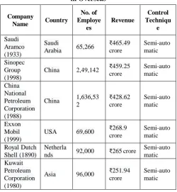
Table 2. Types of Control System used in various industry in Overseas
Company
Name Country
No. of Employe es Revenue Control Techniqu e Saudi Aramco (1933) Saudi
Arabia 65,266
₹465.49 crore Semi-auto matic Sinopec Group (1998)
China 2,49,142 ₹459.25 crore Semi-auto matic China National Petroleum Corporation (1988)
China 1,636,53 2 ₹428.62 crore Semi-auto matic Exxon Mobil (1999)
USA 69,600 ₹268.9
crore Semi-auto matic Royal Dutch Shell (1890) Netherla
nds 92,000 ₹265 crore
Semi-auto matic Kuwait Petroleum Corporation (1980)
Asia 96,000 ₹251.94
crore
Semi-auto matic
From the survey Table 1& 2, it is identified that the process automation isn’t intelligent in automation. Process automation like pressure, Temperature, Level controls are in semi-automatic systems are employed till now. It is highly represented here to implement a fully automatic system is needed to control the process automation. In this present manuscript the nonlinear controller is implemented with real-time small-scale setup and simulated in MATLAB Simulink.
B. SPHERICAL TANK SYSTEM IN OIL AND GAS INDUSTRY
Spherical tank systems are used to hold liquids, compressed gases which is not typically labelled or regulated as a storage tank. Spherical tank could withstand internal pressure easily because of its geometrical structure. LPG is stored under pressure, and the tank must keep this storage in it. Spheres are the strongest shape so they can hold the highest pressures. Also, they have the lowest possible surface area to volume ratio (which minimizes the amount of heat that gets inside through the tank
wall).
Mathematical Modelling and Simulation of
Non-Linear PID Controller for Spherical Tank
Level Control in oil and Gas Industry
Boobalan S, Lakshmi K, Gobhinath S
Company Name
Production No. of Emplo yee Revenues /Year Control Technique Adani Welspun Ltd
oil and gas 24,000 ₹66.2671 billion
Semi-autom atic with DCS Reliance
Petroleum Limited
Petroleum and Natural Gas 187,72 9 ₹36,075 crore Semi-autom atic
GAIL Energy 4,355 ₹50,059.2
6 crore
Semi-autom atic Oil and
Natural Gas Corporation (ONGC)
Oil and gas 33,560 ₹362,246. 96 crore
Semi-autom atic
BPCL Oil and gas 12,567 ₹244,648. 50 crore
[image:1.595.42.303.493.692.2]Gas Industry
There are five basic types of LPG storage, 1. Horton sphere
2. Mounded storage vessel 3. Refrigerated LPG storage vessel 4. Cavern storage
C. Horton Sphere Tank system
Horton spheres tank system is used to safely hold liquefied natural gas (LNG), which is produced by cooling natural gas at atmospheric pressure to minus 260 degrees Fahrenheit, at which point it liquefies. Sphere is the geometrically perfect shape for a system that resists internal pressure.
D. Mounded ground vessel Tank
Mounded tanks (horizontal) are majorly used for storage of Propane / Liquid Petroleum Gas which is generally safer than methods of storing the highly inflammable LPG. This type of LPG Bullets are Large, Horizontal cylindrical steel tanks with of size ranging about 3.5 to 8.5 diameter and lengths about 35 to 70 meters.
E. Refrigerated LPG storage vessel
This type of vessel system is used to store refrigerated and cryogenic gas under higher pressure level. Refrigerated LPG storage vessel type of tanks and their insulation systems must work together to ensure optimum performance for low temperature and cryogenic storage for safe operation.
F. Cavern Storage Tank
Until Fairway Energy commenced operations, all existing commercial crude oil storage in the Houston area has been in above ground tank storage. While above ground storage has its purpose, it is extremely wasteful in terms of space as compared to underground storage and is not protected from catastrophic events such as hurricanes and floods which have so adversely affected other types of oil storage facilities in the past [17], [18]. Highly economical in terms of land area utilization, underground storage has less impact on the environment and provides natural barriers from weather-related events.
II. MATHEMATICAL MODELLING FOR A
SIMPLE SPHERICAL TANK SYSTEM
The spherical tank is basically a highly nonlinear system because of its geometrical shape. The level control the system is also highly complicated one. Hence PID controller is used in this process and the gain parameters were choosen by ZN tuning rule [1], [17]. The proportional integral- derivative (PID) controllers are widely used in many industrial control systems for several decades. S.Nithya, N.Sivakumaran, T.K.Radhakrishnan and N.Anantharaman [1]
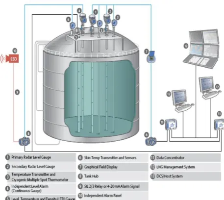
The following CAD Model is used to model the entire spherical tank system with the all real-time parameters.
The proposed spherical tank system, identified as a nonlinear complex structure is shown in Fig. 1, where
[image:2.595.321.550.58.262.2]H = Total height of the spherical tank, f1 = Input flow rate of spherical tank and f2 = Output flow rate of spherical tank.
Fig.1. Spherical Tank and its controllers
Fig.1. Mathematical modeling of spherical tank system is derived based on the structure and the output transfer function is obtained.
The open loop system’s performance is mainly based the PID gain parameters vales. Unfortunately, the values are chosen by trial and error method. Even though it yields good static response, it will take larger in time to tune the PID gain values. It is very difficult to develop the mathematical model of the process to adjust a particular control loop which time varying one [2]. Even though, it is possible to derive a transfer function-based model by conducting a open loop plant test. The open loop plant test is to bring a step change in the manipulated input, and observe the measured process output. Generally, the closed loop process is represented by a model as
(1)
The process plant basic parameters are the static gain (K), the time constant (τ), and the time delay (td) of the plant derived from the transient response.
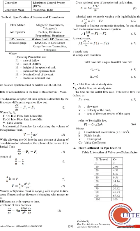
Table 3. The spherical tank system’s specification
Spherical Tank Company
Taishan Spherical storage tank
Maximum Pressure 2.5 Mpa
Inner diameter 10m
Max weight 1,000ton
Max capacity 10,000m³
Materials Carbon Steel Alloy, Stainless
Steel, Non-Ferrous Metals
Pump ABB 3 Phase, 37 Kw, 50 Hp,
415 V, Induction motor Control valve with
Positioner
Siemens Valve Positioner
International Journal of Innovative Technology and Exploring Engineering (IJITEE) ISSN: 2278-3075, Volume-8 Issue-7, May, 2019
Controller Distributed Control System
(DCS)
[image:3.595.57.539.48.842.2]Controller Make Yokogawa, India
Table 4. Specification of Sensors and Transducers
Flow Meter Magnetic Flowmeters,
Yokogawa's
Air regulator Parker,Electronic
Proportional Regulator
E/P converter Watson Smith I/P Converters
Pressure gauge EJA530E, In-Line Mount
Gauge Pressure Transmitter, Yokogawa
Where,
Operating Parameters are: F1 - rate of Inflow F2 - rate of Outflow
H - height of the spherical tank. R - radius of the spherical tank H - Nominal level of the tank r - Radius at nominal level
Mass balance equation could be written as [3], [4], [5],
Rate of accumulation in the tank = Mass flow in – Mass.
The dynamics of spherical tank system is described by the first order differential equation flow out.
(2)
Where F1, F2,
F1-Oil Inlet Flow Rate Litres/Min F2-Oil Inlet Flow Rate Litres/Min V- Tank volume
Mathematical Formulae for calculating the volume of the Spherical Tank.
r3 (3)
While allowing the Oil into the tank the rate of change of accumulation of oil is based on the volume of the nature of the Spherical Tank
(4)
The ratio of
(5)
(6)
(7)
Volume of Spherical Tank is varying with respect to time because if input and out flowrate is changing with respect to time.
Differentiate with respect to time, The volume of tank becomes
(8)
Cross sectional area of the spherical tank is that,
(9)
spherical tank volume is varying with liquid height also,
(10)
We need to find out the transfer function, for that that we need the transient mass balance equation
(11)
At steady state,
(12)
s-steady state
at steady state condition
inlet flow rate = equal to outlet flow rate
F1s=F2s (13)
h
1s=0
(14)F1s - Inlet flow rate at steady state
F
2s -Outlet flow rate steady stateTo find out the outlet flow rate, Volumetric flow rate is defined as
F
2=v
∗
a
, (15)F2 - flow rate
V - velocity of the fluid,
a - area of the cross section of the space
refer to Torricelli's law,
(16)
Where,
g Gravitational acceleration (9.81 m/s2), h Fluid's height
V Fluid speed, Cv- Valve Coefficients
[image:3.595.47.298.383.699.2]G. Flow Coefficient in Pipe line (Cv)
Table 5. Selection of Valve co-efficient factor
% Travel Cv
Gas Industry
The flow coefficient or valve coefficient represented by “Cv”. It is used to calculate the valve size that will govern to allow the valve to pass the required flow rate in it. The following table will provide the essential data to select the perfect “Cv” for the process fluid [9].
(17)
(18)
α, β- non linear element..
To convert linear to non linear we could use Taylor series.
Let we can consider for [10], [11],
H= H-H1s
F=F-F1s
dH1/dt=h1F1-βh1sH1 (19)
Apply Laplace Transform
SH1(s)=h1F1(s)-β(h1s)H1(s) (20)
SH1(s)=h1F1(s)-β(h1s)H1(s) (21)
SH1(s)+β(h1s)H1(s)= h1F1(s) (23)
(SH1(s)+β(h1s)H1(s) )/(F1(s))=h1 (24)
H1(s)[(S+β(h1s))/F1(s) ]=h1 (25)
(H1(s))/(F1(s))=h1/(S+β(h1s) ) (26)
Where, β =α Cv√ 2gh,
α =[H^3/(4πR^3 )]
The Transfer function for the Spherical tank system was derived as a first order with time delay.
General Transfer function for the Spherical tank system
(H1(s))/(F1(s))=A/(τS+1) (27)
Where,
K=2hs/F2 ,
[image:4.595.322.528.67.202.2]τ =4πKhs and F2=Cv√ 2gh
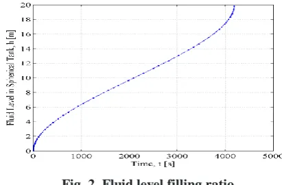
Fig. 2. Fluid level filling ratio
Fig.2. The results are plotted over the amount of time it takes to fill the sphere, which can be easily calculated.
B. Introduction to PID Controller in Oil and Gas Industries
Proportional-Integral-Derivative (PID) controllers are the controller commonly used in process control applications. In many industries it is easy to implement and control. In oil and gas Industry to regulate flow, temperature, pressure, level, and many other industrial process variables are very complex [12]. They date back to 1939, when the Taylor and Foxboro instrument company was introduced the first two PID controllers to automate the process in processing industries. PID controllers are the base controllers of now a days modern process control systems, it will automatically regulate the process otherwise it has been tuned by manually by changing its gains values manually. The controller gain setting is playing a most important role in automation process [15],[16]. If the controller gains values are doesn’t meet the requirement the automation process won’t happen properly. So it needs to select such a way that it leads to minimize the process error. But it is a tedious process. Only by the experience operator can able to choose the gain values. Ziegler-Nichols tuning rule gives sometime better results but not suitable for all process. Because of the improper tuned controller parameters. This is one of the major disadvantages in Ziegler-Nichols controller.
[image:4.595.319.546.572.710.2]III. CONVENTIONAL Z-N PID FOR SPHERICAL TANK SYSTEM
Fig. 3. Block diagram - Conventional Z-N PID controller of Spherical Tank System
International Journal of Innovative Technology and Exploring Engineering (IJITEE) ISSN: 2278-3075, Volume-8 Issue-7, May, 2019
t
0
e(t) dt
d d K e(t)dt i
K e(t) P K
u(t) (28)
The following gains are,
Proportional gain , Kp
Integral gain, Ti = 1/Ki Derivative gain, Td = 1/Kd
Error = Set point value - Process variable value
The above gains formulae derived in John G. Ziegler and Nathaniel B. Nichols. Z-N rulebook and it was originally introduced by Ziegler-Nichols to tune Proportional – Integral - Derivative controller [13].
[image:5.595.319.564.48.173.2]Conventional controller is the controller where the controller parameters Kp, Ki, Kd are all calculated by trial and error method. With the knowledge of field operator, the processes were automated i.e. known as open loop control system [14].
Table 6. Transfer function obtained for various levels
Region (Meter)
Process Gain K
Time
Constant
Transfer function
0-4 0.945 4747.68
4-8 1.3367 13431.25
8-12 1.6361 24659.33
12-16 1.8892 37965.35
16-20 2.1123 53061.5
[image:5.595.62.284.52.151.2]The following Table 7 shows the formulae to calculate the PID controller gains,
Table 7. PID Gain calculation Formulae
Controller Type
Ultimate Gain (Kc)
Integral Time (Ti)
Derivative time (Td)
P Ku/2 - -
PI Ku/2.2 Pu/1.2 -
PID Ku/1.7 Pu/2 Pu/8
IV. SIMULATION RESULTS & DISCUSSION
A. Open loop Response
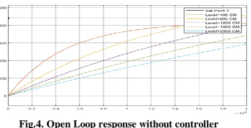
The Simulation Results Fig.4 shows the open loop response for the regulator response of the level system at level 400 cm,
(29)
Fig.4. Open Loop response without controller
From the MATLAB simulation results it is identified that the level of the tank couldn’t be sustained its setpoint.
B. Closed Loop Response
At Level 400cm, Derived Transfer Function is follows as,
(30) [image:5.595.312.542.394.507.2]
The following Simulation Results shows at level of 400 cm. The closed loop response for the level system static response parameters. the closed response of the system is also doesn’t meet the setpoint requirement. Because the system is basically a nonlinear system one. So, it is highly recommended to implement a nonlinear controller to that system.
Fig.5. Closed Loop response without controller C. Conventional ZN Method
The following Simulation Results shows the PID controller response for the regulator response of the level system at level 400 cm
[image:5.595.46.296.565.632.2](31)
[image:5.595.295.547.571.837.2]Gas Industry
Fig.6. shows the PID controller tuned level control simulation MATLAB. It shows the efficient error rejection between its output to setpoint. It has better error rejection capability, it yields the better regulatory response in offline. Even though it was proved the good results, it has some draw back during dynamic transient period of the system.
D. Comparison Results
At Level 400cm, the Derived Transfer Function,
(32)
The following Fig.7. Simulation Results shows the overall comparison of the open & closed loop and Controller response for the regulator response of the level system at level 400 CM
Fig.7. Response of closed loop vs Non-Linear PID controller
V. CONCLUSION
In this research article, the mathematical modelling of spherical tank is derived as transfer function with the help of mass balance equation and differential equation. The simulation results were obtained for open and closed for various level liquid. The results are compared with open, closed, ZN PID tuned controller. The gains were chosen by trial and Error method with the help of field operator. ZN based PID controller yields the good response over closed loop response in offline mode. The response of the open, closed, PID controller response are simulated. But here the chosen of gain parameter are made by trial and error method. Due to that Dynamic response of the system doesn’t meet the requirement. In future the PID gain values are trained and chosen by evolutionary algorithm.
REFERENCES
1. Loganathan, N., Lakshmi, K., and Arun Venkatesh, J., “ A Robust Energy Management System for Smart Grid” International Journal of Advances in Intelligent Systems and Computing (ISSN: ), Springer Series, Vol. 467, pp.423-435, 2017.
2. Lakshmi, K. and Vasantharathna, S., “Gencos Wind-Thermal Scheduling Problem using Artificial Immune System Algorithm”, International Journal of Electrical Power and Energy Systems (ISSN: 0142-0615), Elsevier, Vol.54, pp.112-122, 2014.
3. Lakshmi, K. and Vasantharathna, S., “Hybrid Artificial Immune System Approach for Profit Based Unit Commitment Problem” Journal of Electrical Engineering and Technology (ISSN: 1975-0102), Korean IEEE, Vol.08, No. 05, pp.959-968, 2013.
4. Radhamani, R, Lakshmi, K, and Vijayagowri, G., “Fuzzy Optimization of Line Current Harmonics for 12 Pulse Converter”, International Conference on Recent Advancemets in Electrical Sciences, January 2010, Tiruchengode, India.
5. Jayaraman, L., Vijayakumar, K., Nandagopal, V. and Rameshkumar, K., 2018. Implementation of ILC based Gain Scheduled PID Controller for Non-Linear Spherical tank Level Process. International Journal of Pure and Applied Mathematics, 118(18), pp.4637-4644.
6. Carvajal, J., Chen, G. and Ogmen, H., 2000. Fuzzy PID controller: Design, performance evaluation, and stability analysis. Information sciences, 123(3-4), pp.249-270.
7. Lee, Y., Lee, J., & Park, S. (2000). PID controller tuning for integrating and unstable processes with time delay. Chemical engineering science, 55(17), 3481-3493.
8. Su, Y. X., Dong Sun, and B. Y. Duan. "Design of an enhanced nonlinear PID controller." Mechatronics 15.8 (2005): 1005-1024.
9. Sundaravadivu, K., B. Arun, and K. Saravanan. "Design of fractional order PID controller for liquid level control of spherical tank." 2011 IEEE International Conference on Control System, Computing and Engineering. IEEE, 2011.
10. Kumar, D. Dinesh, C. Dinesh, and S. Gautham. "Design and implementation of Skogestad PID controller for interacting spherical tank system." International Journal of Advanced Electrical and Electronics Engineering 2.4 (2013): 117-120.
11. Sakthivel, G., T. S. Anandhi, and S. P. Natarajan. "Design of fuzzy logic controller for a spherical tank system and its real time implementation." International journal of engineering research and applications 1.3 (2011): 934-940.
12. Yadav, Shekhar, Santosh Kumar Verma, and Shyam Krishna Nagar. "Reduction and controller design for fractional order Spherical tank system using GWO." 2016 International Conference on Emerging Trends in Electrical Electronics & Sustainable Energy Systems (ICETEESES). IEEE, 2016.
13. GirirajKumar, S. M., Bodla Rakesh, and N. Anantharaman. "Design of controller using simulated annealing for a real time process." International Journal of computer applications 6.2 (2010): 20-25.
AUTHORS PROFILE
Mr. BOOBALAN S Received B.E- EEE at K. S. Rangasamy College of Technology and Master of Engineering in Control and Instrumentation Engineering at Kongu Engineering College. Doing part time Ph.D. in Sri Krishna College of Engineering and Technology (Autonomous) affiliated to anna University, Chennai. Research Area: Process Automation, PID Controller Tuning by Various Evolutionary Algorithms, Bio Signal Processing.
Dr. LAKSHMI K Received M.E. and Ph.D. Anna University, Chennai in 2004 and 2014 respectively. She is currently working as a Professor & Head of the Department in Sri Krishna College of Engineering and Technology, (Autonomous) Coimbatore, Tamilnadu, India. Research Area: field of control of electrical power systems.