Development of a single drum chopper concept for a sugarcane harvester
104
0
0
Full text
(2) INTRODUCTION. Abstract: This chapter presents the background and 7notivation for this study. The potential. significance ofthis research is discussed along with the aiJns and objectives ofthe study..
(3) 2. 1.1. Background and Dlotivation. Australia is currently one of the world's largest exporters of raw sugar and a nUl11ber of rural areas in North Queensland and NOlthern NSW are dependent on the industry for survival. Presently, the sugarcane crop is harvested by lnechanicallneans, after which, it is processed in lnilling facilities for the production of raw sugar.. However, a global push towards. renewable energy has seen increased interest in the use of the sugarcane crop for energy production. This process, terlned cogeneration, requires a higher proportion of the total bioluass to be sent to the IniU in order for it to be econolnically viable. The adverse affect of this is a significant reduction in bulk density of the harvested Inaterial, and therefore transport costs to harvester owners and Inillers significantly increase due to the volunle dependent transpoltation Inethods. The bulk density of the harvested lnaterial is strongly affected by the lnanner in which it is billeted in the harvester chopper systeln.. Current. chopper systelTIS are linlited in their capability to vary billet lengths and therefore bulk density. Hence, if cogeneration is going to be successful in the sugar industry, there is a strong need to develop a chopper systelu which is capable of Inaintaining material bulk density as the propoltion of retained biolTIass is increased. Despite the perceived benefits, relatively little- research has been devoted to designing new, luore effective chopper systellls.. Most changes to the systelTI have involved slllall. lTIodifications to existing systelus, ultiJnately only providing a 'quick fix' to the problelTI. As luore lTIodifications are lnade to the existing system, there is a belief within the industly that chopper efficiencies are decreasing, resulting in luore losses in the harvesting process. Losses in the chopping process are a well knowl} side-effect of billeting cane during harvesting, yet current systenls far fron1 lninilnise the losses associated with this process. Billet quality and losses during billeting are issues fundalnental to the lnaxiluisation of sugar quality and sugar recovely. Cane and juice losses during: billeting in current harvesters have been estilnated to be costing the Australian industry. over $35 lnillion a year. Hence, there is. a strong case for developlnent of a lnore efficient chopper systeln. The inability of current chopper systen1s to produce l1igh quality billets of desired length at increased pour rates has provided inspiration for the research and developluent of alternative chopper systelns..
(4) 3. 1.2. Research context. Mechanical harvesters have been universally adopted in the Australian sugarcane industry since the 1960s. Over this tilne, a nUlllber of different chopper systetns have been developed and trialled. The fundatTIental problem relnains that past and present systeills l1ave struggled to keep pace with requiretnents of a changing and expanding industry. The stalting point for the developlnent of a new chopper systeln Blust therefore begin with a review of existing designs and design theories. This research is not litnited to the sugar industry, as there are benefits to be gained frotn in an investigation into chopper concepts utilised in similar agricultural industries. In light of this, the current study focuses on developing a new chopper systeln for a sugarcane harvester.. The performance of the cOllcept will be initially analysed ustng. laboratoty experitnents and nutllerical nlethods. Positive results frOtll this patt of the study will give confidence for the construction of a prototype for experilnental testing.. The. prototype will be tested under 'real harvesting' conditions, ultitTIately providing insight into the expected perfortTIance of the concept. The prototype will be assessed on its ability to handle full scale feed rates, it's ability to provide COl1sistent preset billet lengths and also on it's billet quality and cane and juice losses. At the end of this study, a new chopper concept for a sugarcane harvester will have been developed and thorough]y tested.. 1.3. Aim. The aitTI of this thesis is to develop and exatnine a new chopper concept for a sugarcane harvester. A review of existing research on. chopper systetTIs in the sugarcane and sitnilar industries will provide the basis for the concept developnlent.. The perfot1TIance criteria for. the developed systetll will be based on the current and predicted future industty requirelnents including variable billet length and systetll efficiencies. The concept will be evaluated using experitnental and conlputational tnethods.. The project also aims to construct and. experinlentally test a prototype of the developed ,cbncept.. Finally, the project ailTIS to. provide an understanding into the defortTIation behaviour and resulting stalk danlage present during the billeting of sugarcane.. 1.4. Scope. The scope of this study includes: a) Conducting a review of literature on billeting system designs and sugarcane stalk tnaterial propetties and behaviour when cut..
(5) 4 b) Perforlning a set of laboratory experitnents to gain an understanding into the stalk defornlation behaviour when cut in by a single knife against a stationary anvil.. c) An investigation into a new chopper systenl for a sugarcane harvester. d) The creation and application of a dynatnic finite elelnent lnodel of billet trajectoty through the proposed chopper systeln. e) The developInent and construction of a prototype of the proposed chopper concept. t). A set of experitnental tests evaluating the perfot1nance of the prototype chopper systeln.. 1.5. Thesis outline. Chapter T\vo is a literature review of published works relevant to the developlnent of a novel chopper concept. The pettinent literature on past and present sugarcane harvester chopper concepts, including published works on chopping systelns in similar industries is reviewed. All relevant infornlation affecting the chopping process including the physiology and tnechanical properties of cane is presented.. Chapter Three describes a set of laboratory experinlents on the single knife slicing of sugarcane against a stationaty anvil. The affect of a nUlnber of paranleters on the quality of the cut and the behaviour of the stalk are tested. The deforlnation behaviour and resulting stalk end dalnage is discussed, ulthnately giving insight into the cutting process which Inay be expected froln a single drunl chopper systetTI.. Chapter Four details the process undergone in the developlnent of the single druln chopper concept. The conceptual design of each conlponent and the theoly followed is detailed throughout this chapter.. Chapter Five describes the developlnent and testing of a dynalnic Inodel of the proposed chopper systetll. The affect of a nUlnber of design and operating paranleters on the billet trajectory is discussed, and based on these results COl1clusions are lnade as to the suitability of the concept for use in a harvester.. Chapter Six describes the developlnent and experitnentaI testing of a prototype of the proposed chopper systetn. The affect of a nutnber of operational and design paratTIeters on the efficiency and quality of the cut is assessed under full capacity conditions. A clear -explanation of the causes of billet dalnage during the single drum chopping process is.
(6) 5. presented and conclusions on the effectiveness of the proposed single drum chopper systetn for use in a sugarcane harvester are tnade.. Chapter Seven gives conclusions drawn froln the study. ReC0111Inendations for the fluther developlnel1t of the concept are also detailed..
(7) 6. LITERATURE REVIEW. Abstract: This chapter reViel1JS pel~tinej1t literature on past and present sugarcane harvester chopper concepts, including published works on chopping syste111S in siJnilar industries. All relevant infornlation affecting the chopping process including the physiology and 111echanical properties ofcane is presented..
(8) 7. The mechanic:al sugarcane harvester. 2.1. he first conln1erc aI luechanical sugarcane harvesters were inv nted and trialled in the early 0. 1940- s after th ind lstrywa struggling to expand due to the labour lutel sive process 0 111anu.ally cutting tll. \;rup. t=v~r. y~ar.. With. l-l~. pot udal to deliver a mu h higher output. with he us ofnl°ninlal wages he mechanical harvester Allstraran sugar indu try. Tl ere ar no. as quick] adoped hr ughout the. appro~7inlately 1200. lechal leal harvesters in use. arolllld Australia. John Deere and Case IH are th two COJllpanies which constr ct. 1. odern. ugarcane harvesters and both macJline operate o.n the same basic principles.. Figure J Most recent 1110del John Deere track dri en sugarcane choP1Jei' harvester The prirnar function of the sugarcane harvesteri~ to r 1110V th. cftne sf::. lks fronl the field. and d Ii er hel to tl e haul-out bin. This i done by removing the leafy top of the pla.n and cutting the stalk i-to Hlanag abl lengths ca. led b·))etso 'The 111achine 1 ust also cu the crop. wit, Olut causing significant danlage to the stalk during 'he proce T. lC. Il-:Lcchanical sugarcane lJarveslc;r j . a. UlltJ-pa:s~. lnalihint: aud as il ravt:.ls down. ~ach. the cane is fed into he front mach One- is processed and e rits through the "ear. fnn(l::ll. ent~l. con pOllents of a 11lechal1ical har- ester are S110 n in Figure 2.. -ow. The.
(9) 8. Secondary Extractor. Primary Extroclor. \. Base Cutters. Figure 2 - Fundalnental C07J1pOnents ofa 7nodern 7nechanical sugarcane harvester (BSES,. 2002) The Topper is the first part of the ll1achine to CaIne into contact with the cane and it has the purpose of cutting off the leafy top of the cane. TIle height of the toppers can be adjusted by the operator when cutting cane of variable height. An effol1 lnnst be lnade to relnove as lnnch of the leafy top as possible as this reduces the cleaning load on systelns fUl1her on in the process. The Crop Dividers (Spirals) direct the cane stalks illto the Inouth.ofthe harvester. These are pal1icularly useful in lodged cane, where the stalks have collapsed into neighbouring rows. Once the leafless stalks have been knocked down by the Knockdown Roller and Finned. Roller, they are severed off at ground level by the Basecutters. The basecutters are two discs with replaceable blades that rotate parallel to the,.. ground. The secondary objective of the basecutters is to feed the cane butt first into the roller train. The Feed Rollers (or Roller Train) pick the cane up from the basecutters and feed it longitudinally into the choppers. The top roller of each pair is lnounted on a pivot and can travel up and down to account for surges in the feed. Each roller has uniquely shaped fins which playa vital role in straightening the stalks before they are fed into the choppers. The Chopper System accepts the straightened mat of stalks and trashfroln the feed rollers and cuts it into billets of unifornl length. The choppers also propel the chopped cane/trash into the extraction chalnber..
(10) 9 The Primary and Secondary Extractor fans create a strong upward air strean1 which separates the lighter trash fron1 the cane billets.. These systems have proven to be. responsible for the lnajority of the cane loss in a ll1echallical harvester. The Elevator cOllveys the cane and ren1aining trasIl froln the chopper box into the haul-out using a fljght systeln. All of the components on a sugarcane harvester are hydraulically driven by a l1lunber of pumps connected to the 300 to 350 horsepower diesel engine. Note lnust be taken that the choppers are driven by their own hydraulic pUlnp due to their high power usage.. 2.1.1. The history of chopper systems in sugarcane harvesters The following background all the developlnent of the chopper systen1 in cane harvesters is as described by Hockings and Davis (1999). The concept of billeting cane and il1corporating cutting and loading into one operation was developed as early as the Faulkiner harvester in the 1920s. It was not until Massey Ferguson developed the low cost 515 chopper harvester in the 1950s that the. adv~ntages. of this. harvesting systelll were sufficiently< tangible to be accepted by the industry in the 1960s. To billet the cane, the 515 chopper harvester incorporated a systeln known as the rotary pinch chop. The systelTI was conceptualised, desiglled and developed by engineering staff at Massey Ferguson, and appropriate patents protected the design. The success of the chopper harvester concept spawned the developIllent of alteIl1ative concepts for billeting cane such as the 'swing-knife', 'chop-throw' and alternative. di~um. designs. Since the expiry of the patents. on the rotary pillCh chop in the early 1980's, it has been the preferred systeITI throughout the world. There has, however, been considerable evolution and developIllent in the concept, which. i~. delnonstrated by the cllange froln the original two knife c·hopper druITIs to the lTIOSt recent six knife drUITIs. The original rotary chop was developed as an over centre chop concept where the interacting blades cOlnpleted their engagenlent as they aligned between the centreline of the choppers. An alternative approach was the hoe chop where the chopper blades cOlnplete the cut well before they align between the centreline of the choppers. This design essentially superseded the over centre chop as it offered lower power consulnption, lower cut losses, lower juice losses and lower billet dalTIage. With the exhaustion of Massey Ferguson patents on the pinch chop concept, Versatile-Toft adopted this systeln in their 7000/7700 series harvesters. This systeln was based on designs.
(11) 10. developed by Massey Ferguson during the evolution froln the original 515 to the 305 harvester, and was silnilar to tlleir hoe chop design. This relnained the 'industry standard design', over the following 15 years, and was installed in both Austoft and Calneco Inachines. Perceived problelns with this design led to the developlnent of alternative designs by third party harvester cOlnponent suppliers such as 'Grieves Enterprises', 'WesthillEngineering' and 'Trail Brothers', with a range of other alternative designs being developed by innovative farlners.. Although many of these design's 're-invented the wheel', the level of activity. indicated a high level of dissatisfaction with the standard design.. One after Inarket. conversion introduced by a third party supplier in 1995 included a redesign of tIle knife clanlps and the fitting of rubber rather than steel thrower bars.. This Ineant the systeln. offered a dralnatic reduction in chopper operating pressure and reduced susceptibility to overload, effectively giving a significant increase in lnachine capacity over the stalldard choppers. After liJnited field trials in 1995, both harvester Inanufacturers (Austoft and Calneco) introduced choppers of new design and of larger diameter into their Inachines in 1996. Whilst both designs appeared to reduce power consumption at high pour rates, effectively increasing ll1achine capacity, both Inanufacturers encountered billet quality as a major problem with their 1996 lTIodellnachines. Data froln Inillers and various BSES asseSSlnents repol1ed very high levels of damaged and nlutilated billets being produced by the 1996 lnachines.. This continued to drive a frenzy of fUlther developlnent and a heightened. awareness of other factors impacting on the probleln. An additional entl")' to the Inarket lnade available during 1996 was a chopper utilising unequal drunl dialneters. This gave a blade entI")' configuration initially approxiJnating a blade/anvil configuration. As the cutting cycle progressed, the blade configuration took on an action similar to that of the how chop systenl. design. This concept, tenned the differential chop, has beCOlne the 'industl")' standard' 011. the basis of field observations which have indicated reduced billet dalnage and. extended tilne between knife changes. The differential chop systeIll is the current systeln installed in both the CASE IH (forIllerly Austoft) and the John Deere (fornlerly Calneco) harvesters. The Inost recent changes in chopper systelns have been driven by the desire to cut shorter billets (to increase bin weights). This has seen the increase in the nUlnber of knives on the chopper drullls, where up to six knives per drunl are available in SaIne current systeITIs. The three rotal")' pinch chop systelTIS described above are illustrated in Figure 3 and a photograph of a 1998 Calneco cllopper systeITI is shown in Figure 4..
(12) 1I. 0"'.- e· _entre. ~op. Hoe cll. FigUJ e 3 - ROlar pinch chop s steIn configuration~ (Hockin sand Dm i. Figure 4. 1999). ChoP1Jer s ste111 in a 1998 nlodel anleco hal ester. 2. __ ,Z. Chopper losses Bille. uahty and losses during billeting are i sues fundanlental to the lnaximisatioll of sugar. quality and su a1' recovelY. The move froIn, holestalk to billeted cane had not beell without. problel11s,. Dete' ioration of th cane because of the nunlber of cut urfaces was exacerbat d by daI ag to the bill ts.. With ery little consIstent accu ~ate data publis ed on tlloder cJl0pper systenl losses and effici ] e , BSES undertook a 11lajor project in 1998 to JlleaS ire chopper loss sand.
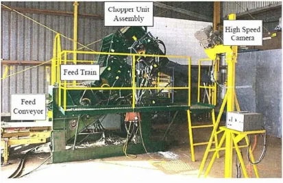
(13) 12 dete11nin,e the optil rlUll1 chopper setup and operating conditions. The results weI' publi, h d b Hockings and Davis (1999). The specIfic objectives of the study Included: 1) QuantifyiIIg the relation hips betw en the cane feed train n01111nal velocity chappel. perIpheral. ni fferent. elocity billet lengh bille le 19th distr"bution and billet quality of choppel~. sy teoll1S at differel1t pour rates.. instantaneous torque loadings. Povver conSlunpt' on and. ere also asse sed.. 2) Quantifying the inhe ~en juice and fibre losses and bille daluage in the cutting process \vi h h different d,es· gns and under clIff; rent harvesting conditions (po r ·ate feed train speed and cane type). l~he. test rig used for he r search was a sta ionary rep icate of a sta ldard 1998 ITIodeI CASE. IH" Austoft 7000 can· harvester feed train and chopper systen1_ The cho.pper Jnodule on th.e rig was inerchangeabl. 0. a different chopper systen s co lld be t sted. TI e fi e chopper. systenlS tes ed were" a 121nch Austoft systeln (standard UlltiI 1995) a current 1998)Ausoft 15 inch system a custom 12 inch Aus oft. syS" eIll,. a W,esthillngineering 15 inch syst. III. and a Massey Ferguson 12 'inch systenl. Cane stalks and tTash were fed into the rig via a COil eyor.. The rig used 11} this tud is s lown i,n Figure 5.. Figure 5 - Chopper test rig used in the B E) trials (Hocking' and Davis 1999).
(14) 13. The results found [r01TI the trials include: 1) The Austoft 15 inch differential chopper systelll provided the lowest losses (in the range of 1.9 to 3.1 percent). 2) Losses were increased in brittle varieties. 3) A roller peripheral speed of 60 to 700/0 of the chopper peripheral speed resulted in the lowest losses. 4) All chopper systelTIS showed a lower degree of loss for a pour rate of 120 tlhr (2.83.3 percent) than at 240 tlhr (4-5.9 percent). 5) Three tilnes lTIOre losses were found when blunt knives were used cOITIpared to new knives.. 6) Mean billet length is independent of pour rate and variety and dependent on feed train roller speed. 7) A lnaxitnum cutting force of 14 kN applied to the cane bundle was recorded for the. 15 inch Austoft differential chopper cutting at a pour rate of 240 t/hr. 8) A InaxilTIUlTI chopper power of 13.4 kW was recorded for the 15 inch Austoft differential chopper cutting at a pour rate of 240 t/hr. 9) Cutting forces and chopper power increased with pour rate, toughness of variety and lTIis111atcil of peripheral speed between cl).opper and feed train rollers.. 2.2. Chopper systems used in siInilar industries. There are a nunlber of other agricultural crops which are harvested in a situilar 'chopping' process. The widest spread of these being the crops in the forage industry. Across the world forage plants are grown for silage which is fern1el!ted to provide feed for livestock. C0l11lTIOn plants used for silage include grass crops such as lnaize and,_ sorghun1. In order for the lnaterial to ferlTIent and dry, the crop is chopped into lengths of between 2 and 50 lnillilnetres during the harvesting process. The following section describes a current chopper systelTI used in-a forage harvester.. 2.2.1. The forage harvester chopper system The forage harvester inspected was a 2002 lllodel Claas Jaguar 830. The choppers in this harvester are used to cut forage Inaterial into lengths of between 4 and 19 lUln.. Each. cOlnponent of the chopper systeln is described in this section.. Chopper Drum The chopper druln has a 700 n1ln dialneter Ineasured fro.lTI knife tip to tip. There are 24 knives on the drUlTI, yet a systeln with 20 blades can be installed if longer pieces of lTIaterial.
(15) 14. are desired. The speed of the druIll is constant at 1200rpIll and is driven lllechanically froln the engine. A schelnatic of the druln is shown in Figure 6.. Shear Bar / Anvil The shear bar in the systeln is lnade out of heat treated tungsten carbide and is reversible and replaceable. It is l1lounted all a Inovable pivot, which is adjusted to lnove relative to the drUIn so as the distance between itself and the knives is kept at a mininlum for the life of the knives. Contact sensors control the adjusttnent, whereby the shear bar is moved in until the sensors detect contact, upon which time the shear bar is nloved back out a fraction and set at that position. The adjustInent process is initiated by an operator in the cab, after which a cOlnputer controls an electric IllataI' which Inoves the pivot on either end of the shear bar pivot asselnbly. A schenlatic of the shear bar and pivot assembly is shown in Figure 7.. Sharpening System The knives on the chopper druln require sharpening to both retain the sharp edge on the knives as well as ensure even wear of the knives. During sharpening, a sharpening stone passes across the outer face of the knives. The drum continues to spin forwards at the saIne speed as operation. The sharpening stone is gradually lowered with every pass to acCOUt1t for wear in both the blades and the stone. The Claas Jaguar 830 has a lowering systelTI which utilises a ratchet InechaniSlTI, whereby the' stone is fitted to a thread and when the stone gets to one end, the ratchet turns the thread, in turn slightly lowering the stone. The stone is passed along the length of the drUITI using a hydraulic ram that is connected to a 2: 1 chain systeln. This ratio forined by the chain and pulleys allows the stone to travel the entire length of the drum whilst the ranl only travels half.. A schelnatic of the stone holder. asselllbly including the thread and ratchet is shown in Figure 8.. Knives The knives used in the Claas Jaguar 830 forage harve-ster chopper systeln are lnade out of heat treated tungsten carbide. The cutting edge of the knives has a slight helical shape, which results in one side of the edge passing the anvil slightly earlier or later tllan the other, depending which side it is. This results in a slight shearing effect, silnilar to the cutting tnechanisnl of a pair of scissors. The inside face of the outer portion of the knife is coated with a spray 011 hardening Inaterial to prevent wear and help retain a sharp edge on the knife as it \vears. The geoll1etry of the knife is shown in Figure 9..
(16) 15. Figure 6 - ScheJnatic ofa Claas Jaguar 830 forage harvester chopper drUlJl (Claas, 2002). 74. £1.11115. o5092t03 JAGUAR 900-830. Figure 7 - SCheJl1atic ofa Claas Jaguar 830 forage harvester shear bar and pivot asseJnbly (Claas, 2002).
(17) 16. 00094z00 JAGU. 900~O. Figur? 8 - Shen1atic ofa Claas Jaguar 830 forage harvester shalpening stone and holder ass f?111bI (C laa.~ . .002. (a.) Top Vie\\l. (c) En.d View Figure 9 -. (b) Unders"de V"ew. d) Angled View·. laas tJaguar 830 forage harl estel chopper knife.
(18) 17. 2.2.2. The use of forage harvesters for cutting sugarcane Recent interest in co-generation at the Inills has seen slnall scale adoption of wilole-crop harvesting, where the total biolnass product is recovered during harvesting. As the current chopper harvester is designed to provide a high quality cleaned product for sugar production, there are unnecessary costs and inefficiencies when using it for harvesting a crop for biolnass fuel recovely. In an attelTIpt to find a faster, lTIOre econolnical way to harvest the whole crop for fuel production, forage harvesting equiplnent has been trialled. Jakeway (2003) conducted trials cOlnparing the efficiencies of a standard chopper harvester against a forage harvester for whole-crop harvesting and data was collected on equiplTIent productivity, paliicle size, Inaterial bulk density, and actual biolnass recovery.. The. sugarcane harvester used in the trials was a CLAAS 2000. Although this is slightly different froln the Austoft and John Deere harvesters seen in Australia, it relies on the saIne principals to harvest the cane. The forage harvester tested by Jakeway (2003) was a CLAAS Jaguar 880 (sinlilar to the 830 lTIodel described in section 2.2.1). Key production data found froln the trials is shown in Table 1.. Table 1 - Harvester production data (Jakeway, 2003). Parameter. ",. ,/ ", 'Carie HarVester. Forage Harvester. ... 9.1. 11.6. Avg. harvested lnaterial particle size (InlTI). 355.6. 15.2. Transpo11 bulk density (kghn 3 ). 132.9. 219.4. RecovelY yield, t/ha. 93.7. 67.0. Avg. residue left after harvest (t/ha). 18.2. 62.6. Avg. effective productivity (t/hr). The effective productivity was defined as the cane harvested during actual working hours. It is repo11ed that the conventional cane harvester perforIned Blore reliably, with the forage harvester having a nUlnber of breakdowns.. The increased productivity of the forage. harvester is a result of having a Illore powerful engine, and a wider cutting width. The average harvested Inaterial size (billet length) was significantly different between the two lnachines, which resulted in a significantly higher bulk density of the Inaterial froln the forage harvester..
(19) 18. he recovery yield was reported to have been influenced by he quali( of he crop being cut. The crop used in this set of trials was lodged and not in a neat stat ding arrangelnent The result of which was a sIgnificantly lowTer recovery yield of the forage harvester due to its. inability to collect fallen callie off the ground.. The aITIOunt of residue left by the forage harvester was a r suIt of the header cutting the cane above g't ound level.. However th. ba ecutters on tl e calle harvester cut the stalk of at or below ground level luiniJnising the. resid ~1.1'e left in th,e field. t is obvious froln thi se _of trials that tiler are advantages to be seen in productivity rates and an increase in bulk density if SOlne pr"'nciples froln forage harves ing equipment were. adopted in cane harvesters. Howevel- a s andard forage harvestervvithout cane harvesting ITIodifications is not quite capable of collecting the sprawted cane crop into the lnachine without significant losses.. 2.3. The physical ,s,tru1cture ofs,ugarca'oe. Sugarcane grows froln billets planted beneath the soil during tl e plantil g process", Shoots stelll fronl each billet an,d at 111aturlty a sta k is between 2 and 3 lneres tall and btween 12. and 50 111illinletres in dial11eter depending on val iety and gro ing conditions. Stalks gro\\r in bundles and share a. COlTIlnOn. root system which steIns franl the pare'l1t billet. Figure 10. shows a picture of a 111ature crop of sugarcane.. Figure 10 ~ Mature crop ofsugarcane'prior to harvest Th,e sugarcane plan consists of leaves up to 1 5 Inetres in length a (lched to the top of the. stalk. The chlorophyll in the lea.ves absorbs energy frolD the sun and combines with carbon dioxide and watet" to produce the sugars stored as juice in the stalk. The stalk is defined as.
(20) 19. the portion of the plan above th gro ]nd whIch bear· tle leaves and flo 'er. A nlature stal. is lnad up of between 30 and 40 joint which are seglnented by hard disc shaped lode located at approxhnately equal intervals. The g ometry of the cross section of a sl,garcan stalk -aries. ith dif£ rent varieties but in general it Inaintains a relative y circuar shape.. The sugarcall stalk has a nUlnbel of func ions,. hich 111clude:. suppolii g the leave and flo er parts· conducting \¥ater and soil. t . ·ents to th leaves'. 1110ving the nlanufactured foods to othel parts of the plant storing sugar in the form of s crose. The ugarcane salk has a fibrous ll1atri frOIU ""'hich tlle plant gain its strength and ability to prodllc. ugars i 1 the forln of UClose. Th. int l"llOde section. fibrovascular bundles as can b. hard outer kin and a soft inner pith region re"nforced b see jn. f tIle stalk is l1lade up of a. ig" re 11.. Figure 11 -. C~ros. . section through a sugarcane stalk inter-node. J Epiderlnis' 2, thick-. vralled cells jornling the rind" 3&4 1 ascular bundles ofdiffeJ ent 'izes 5, clerenchY171a' 6; t'. pith tissue. (Van Dillewijn 1952). .!. he stalk's outer skin. '110'''711. as the ep' de:rmi. i lnade up of tl i.e.. -~a'. led elongated ce ls_. Located beneath the pidennis lie everal layers of rigid, woo dy sclerenchYl11a c lIs, also I.. kno n as th cOlte'. These c-ells contail t- e p'. gnJe.nt of Jle cane and when. co l1bined \ ith.
(21) 20 the epiderlnis are terlned the rind of the cane. The rind serves to provide strength and protect the inner tissues, which consist of vascular bUlldles and storage cells. The vascular bundles. cOlnpris~ the. bulk of the stalk interior and increase in density along the. radius. The vascular bundles run in a parallel direction wllilst in the internode, and as they lTIOVe into the node region, luany of thelTI branch or bend to the leaves or buds.. This. convergence in the nodal region results in the node being harder and luore brittle than the internode. Inside the vascular bundles are the fibro-vascular bundles. A fibro-vascular bundle consists of a sclerenchylnatous sheath which encloses an outer layer of xylelTI and inner layer of phloelTI. The xyleln is vascular tissue which conducts water and lTIineral salts throughout the plant, whilst the phloeln tissue conducts Inixed food. Making up the remainder of the cross section are parenchYlna cells that are filled with high sucrose concentrated juice. The physical structure of a green sugarcane stalk can be divided into three Inain categories of engineering interest:. 1) Insoluble solids, which include the rind and fibrovascular bundles (8 - 18%) 2) Soluble solids, including sucrose and iInpurities (10 - 16%) 3) Water (73 - 76%) Whilst the stalk is the part of the plant of Inain interest when lnilling for sugar, the recent interest in using the leaf and trash for .power generation has Inade it a valuable part of the crop. Depending on variety and growing conditions, between 10 and 20 percent of the total Inass of a lnature crop of green sugarcane is leaf or trash'lnaterial.. 2.4. The mechanical properties of sugarcane. During the billeting process, the cane stalks are exposed to various Inechanical effects. It is a requirenlent of this process that an applied force be '·accoll1panied by a deforlnation either great enough. or slight enough to avoid dalnage to the stalk. For this reason, the nlechanical propelties of the cane stalk are iInportant. These Inaterial prope11ies will essentially affect the material's sensitivity to injury and dalnage. The Inechanical propelties of the sugarcane stalk are conlplex as they:. 1) Vary within an individual stalk due to the different structures such as the rind and the nodes 2) Are influenced by external factors such as Inaturity and growing conditions 3) Depend upon varietal characteristics.
(22) 21. It is well known that agricultural Inaterials exhibit different behaviour under static and dynalnic loads. The stress-deforlnation relationship for these biological Inaterials depends greatly on the rate at which they are deforlned.. This ilnplies that a tinle dependent. relationship exists between stress and deforlnation. ComlTIonly, lnaterials exhibiting such tilne dependent effects are terlned viscoelastic, and have partly solid, partly liquid properties. The action of the knife cuttillg the stalks in the chopper systeln can be represented by an ilnpact load. Keenliside (1985) investigated the bending strength of sugarcane under inlpact loading. A halTIlTIer nl0ved veliically downwards at a speed of 0.762 ln/s to strike nlidway along a cane saJnple placed on two anvils 76 lnm apali. Hamnler depression, applied force and total energy were recorded to allow plotting of the stress-strain and energy-strain curves, delnonstrated in Figure 12.. FrOln the infol1TIation provided in the curves, Keenliside. calculated the specific energy to fracture, the Young's lnodulus, the nlodulus of rupture and le toughness of the cane. The average results of these Inaterial propeliies of nine repetitions r five varieties of cane are shown in Table 2.. upper yield or rupture point. stress. elastic limit proportional limit. energy. (load). lower' yiel dpoint fracture. strain (depression). Figure 12 - Typical stress-strain curve for sugarcane in bending (Keen liside, 1985) Table 2 - Mechanical properties ofsugaPcane (Keenliside, 1985) Cane variety. Energy of fracture (J/m 2). Young's lTIodulus (MPa). Modulus of rupture (MPa). Toughness (kPa). CP65-357. 5530. 76.2. 13.0. 302. NCo-3IO. 5200. 58.4. 10.8. 346. L60-25. 5760. 63.7. 12.2. 263. CP70-321. 4990. 59.6. 12.0. 409. L79-1003. 7110. 105.6. 16.5. 401.
(23) 22 The high fibre cane L69-1003 had lnuch greater stiffness and strength than the other varieties, while the Young's lnodulus of the low fibre variety CP65-357 was higher than the relnaining three. Keenliside therefore concluded that the tnechanical properties of cane are related to fibre content.. 2.5. Cutting sugarcane. Cutting force and cutting quality are the Inost ilnportant factors when considering the tnechanical properties of the cane stalk for the billeting process. Research published by Kroes (1997) investigated the behaviour and tnechanical propelties of sugarcane when it is cut by the basecutters of a harvester. However, this cutting regitne differs froln the billeting systelTI as the cut is not lnade against an anvil and the l(nife geolnetry is different. Persson (1987) studied the single knife and counter-shear cutting process of timothy grass. A cOlnpression stage of the nlaterial is described before the penetration of the blade edge into the stem as shown in Figure 13.. During this cOlnpression stage, the stenl section lnay. collapse and split in the high stress regions. A typical force-displacelnent curve for this type of cut would look sitnilar to that shown in Figure 13. pre-co~pression. original section. ~~. after the cut. phase,of cut. .. blade counter. shear. stem section prior blade. penetration force. o. cut section. blade displacement Figure 13 - Behaviour oftil11-othy gra~s during cutting with knife and counter-shear (Persson, 1987).
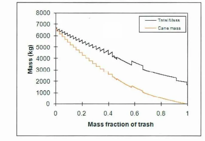
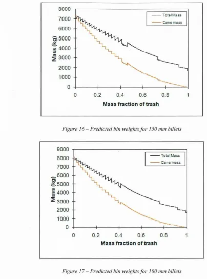
(24) 23. Whilst the work of Persson (1987) describes a cutting regiIne siInilar to that of a single drUlTI chopper systenl as seen in a forage harvester, the lTIaterial prop'elties of tilTIothy grass display a lnarked difference froln those of sugarcane. Hence, results froln this study can not be directly applied to this research, however such previous research gives insight into' what can be expected when cutting sugarcane.. 2.6. Predicting the bulk density of a cane and trash ntixture. With rising fuel prices and increases in labour costs, transportation of the cane tnaterial [rOlTI the field to the IniU nlust be optiInised to reduce costs to harvester operators and lnillers. Increasing the bulk density of the cane billet and trash lnixture results in a decrease in VOlU111e for a given tnass, and therefore volutne dependent transpol1ation costs are reduced. Hence, it is beneficial to the industry to be handling a lnaterial with the highest practical bulk density that does not result in a significant decrease in harvesting efficiency. Calculation of the bulk density has historically been done by in-field trials, but recently a model has been developed for predicting the bulk density for an arbitrary cane billet and trash lnixture. TIle algorithtn developed by Lewis (2006) implelnents a layered approach to calculate trash bulk density through the height of the bin as well as an empirical lnodel to predict the bulk density of the cane billet sections. The outputs [raIn the algorithlTI include total bulk density of the cane billet and trash Inixture and also the predicted bin weight for a specified bin geolnetry. A prograln was developed which .harboured the algorithIn and a screen shot of the user interface is shown in Figure 14 This progratn was run for the set of cane atld trash parameters correlated to this study. Billets lengths of·200, 150 and 100 tnnl with a dialneter of 25 Innl were entered into the progranl and the resulting predicted bin weights for a stand'ard five tonne bin were calculated. The results are shown in Figures 15 to 17..
(25) 24. RE.... _TS. -1 lets "Bets. 3 .5 2. _ 2.~~. 2.54. 15 ... a Figure 14 -Screenshol o..l'(a) input panel anef (b) results panelfor trash la, er calculator (Lewis 2006). _0_0 --000. 2. 0. o. Figlll e 15 - Pr dieted bin. eight for 200 mm billet.
(26) 25. 0000 ,000. J. -. i - 9-55. 6;000 ~"OOO CD. ~. 4 00. , SOOO. 2 00 1000. o. o. 0.. ;. 0.. -. 0.2. a s rralctll'on. Figure. 16·~ Predicted. bin weights for 150 I1UI1 billets. 9000 8000. 000 ~. ,1000. ~"OOO I. 1000 000. 2000 000. o. o. 0.2. Figure 17 - Predicted bin 111elghtsfor 100 111m billets A,na)ysis of Figures 15-1 7 shows the advantages of cutting sJ10rter billets throughou the. lnass fraction of trash lange. For a lnass fraction of trash of ] 0 percellt, the bin weight is increased by 20 percent wl1en the billet Jel1gth i~ reduced from 200 nlnl to 100 film All three figQres show a reduction in bin weight as the lnass. order to maintain bin weights as the luass. fi~action. fi~actjon. of tras.h increases. Hence in. of trash is increased the bIllets IUllst be. cut into sllolter lengths once again providing motivatiol] for a study into billeting systelTIS that are capable of doing such a thing..
(27) 26. 2.7. Conclusions from the literature review. The review of current and past chopper systelns in sugarcane and forage harvesters has provided a solid foundation fronl which to begin the present study. It was found that a. nlunber of different billeting systeln designs have been ilnplelnented in the sugar industty over the years and each has had their advantages and disadvantages.. Literature on the. lnechanical properties of a sugarcane stalk and the linlited published works on its deforlnation behaviour when cut are presented.. A review of a recent publication on. predicting cane and trash lnixture bulk densities has reinforced the possible advantages to be gained froln a new chopper systeln that is capable of cutting shorter, luore COllsistent billet lengths. Attention is now turned to developing and testing a new chopper systeln..
(28) 27. LABORATORY BILLETING EXPERIMENTS. Abstract: This chapter describes a set of laboratory experilnents on the single knife slicing ofsugarcane against a stationaly anvil. The affect ofa nUJl1ber ofparal11eters on the qualif)J of the cut and the behcrviour of the stalk are tested. An understanding of the defor111atiol1 behaviour and resulting stalk end dalnage is gained, ultbnately giving insight into the cutting process lvhich 1nay be expected11"0111 a single drUJ11 chopper systen1..
(29) 28. 3.1. Aims. The objective is to gain an understanding into the Inechanislns present during the siIlgle knife slicing of sugarcane stalks. The specific ailns of this chapter are as follows:. 1) Design and construct a siITIple single knife slicing apparatus which provides repeatable and accurate data during the laboratory experimental testing. 2) Develop an experiInental plan that provides objective results and valid conclusions froln the set of experinlents. 3) Deterlnine the effect of a nUlnher of parameters on the quality of cut and resulting stalk end danlage. 4) Gain an understanding into the Inechanislns present during the single knife cutting process and ultiInately the causes of billet dalnage.. 3.2. Apparatus. The apparatus used was a specifically constructed rig of which a single knife travelled past a stationaly anvil to cOlnplete the desired single knife cut affect. The basis for the design and construction of the rig was" one of silnplicity and safety, where funds for a larger and ITIOre conlplex apparatus for testing were saved for the prototype rig discussed in Chapter 6.. In an effolt to reduce apparatus cost and construction tilne, the knife velocity was obtained using a sliding fralne on guide wires that was raised to a predeterlnined height and allowed to fall under gravity. Relying on gravity alone.to energise the knife linlited the Illation of the knife to the veliical diInension for the ability to provide the Inost repeatable velocity and action. The Inain cOlnponents of the testing apparatus are shown in Figure 18. The guide wires were pulled tight using an overhead gantly so as there was reduced chance of lateral movenlent of the sliding fralne.:The tolerances of the holes in the fralne where the wires passed through were also low to reduce unwanted sideways Inovelnel1t of the fralne. The knives used were standard 95 InlTI Austoft differential chopper knives, and were replaceable via bolts on the underside of the sliding fralne. The anvil on the rig had three angle settings so as cutting stalks at various angles was possible. TIle fraine which allowed for the three different anvil angle settings is shown in Figure 19..
(30) 29. Figure 18 - Laboratory cutting experilnent apparatus. FigUl e J9 - AnY;l frallle. 'hOl1. ing the 1110unts for the different angle settings.
(31) 30. The a lvil franle was adju ·abl relative 0 the guide. ires 0 as the dis ance bet e 11 the. knife and an' i co ld e adjusted. H·gh den it polyethylene (HDPE) wa used as the an i. Inaterial in the rig due to its treIlgth and ability to absorb the cOIllpressive load seen by t1 e at vi] "n this op ration.. t. J w'a no used for the anv'l edge lnateriaI as contac 111ad b the. kn' e on t e stee anvil would compro111ise the integrity of the apparatus. Yet such COl tact. 111ad on the edge on the HDP anvil \ auld lnuch less drarnaticall Ie u]t in chipping of the HD E and 111uch less fotce on the apparatu . A schelnatic of the cutting process produced by the apparatus is shown In Figur 20.. I Anv,il angle. Side Vie,,,. Front View. chell1atic afthe cutting l)roce~ studied in thi set qf' xperiJnents. Figure 20 -. 3.2.1.. strumentation and recording devices. HIgh peed ideo footage of t le cutting process ¥as i lperative in t. analysis of the cutting. process. A Redlake Motion Extra HG-IOOKhigh speed calnera and acconlpanying cOlnputer software were us d to record the process at 2000 fi anles per s condo 4. by the calnera were in black. digita. ,3.3. h llna.ges produced. and white and fer downloaded to the conI ected computer in. fOllTI.. Description of the exper,-ment. 3.3.1. Var-ables Thi e, peri- ental investigation. as carried au . to determine th,e factors affectjng th qua it. of cut produc d by the sing e nife slicing of a sugarcane stalk.. The outputs. frOJll. the. e periJnent were lnass loss data and high speed footage of the cutting proce s.. The. quantitativ,e mas. The. loss data for each est is the dependent quantitativ. variable.. controllable ind'ep ndent variables that contri uted to the variabe mass los dataw -e; anvil.
(32) 31. angle, knife condition, knife speed and calle variety. The levels selected and the units of each independent variable are shown in Table 3. Table 3 - Levels selectedfor each independent variable. Anvil angle,. e. Degree. Knife condition, K f Knife speed, K s Cane variety, V. 30,60,90 Sharp, Blunt. "ln/s. 2,4. Q208, Q117. Anvil Angle Changing the anvil angle results in a change of the angle between the longitudinal direction of the stalk and the direction of the knife travel. An understanding of the affects of changing such a cutting paralneter assists in deternlining the dalnage lnechanisnls present during the cutting process. The three levels chosen for this 'variable are 30, 60 and 90 degrees. These levels provide a Ininin1uln, Inaximuln and in between value for the range of angles interested in for the chopper design. Knife condition Two levels of knife condition were used in this set of experilnents to deterlnine the effect of knife sharpness on the quality of cut. The sharp knife was a brand new blade as supplied fron1 the nlanufacturer for installation in a harvester. The blunt knife had a one n1illilnetre flat surface on the cutting edge. This flat edge was achieved by grinding the edge of a new blade. Figure 21 shows the Ineasurelnent of the thickness of the cutting edge on the new and blunt knife..
(33) 32. Figure 21 - Cutting edge 1'Fidth ofthe new and blunt knife. Knife speed The lnaxilnuln knife speeds used in this experitnent were litnited by the capabilities of the apparatus. It was deterlnined froll1 prelitninalY testing that the Inaximu]n safe and repeatable speed achievable by the apparatus is 4 In/s. Although this is significantly lower than the Inaxilnuln knife speed of 18.3 In/s seen in the proposed chopper system, it is sufficient for the ainls of this palticular set of laboratory experilnents. A lower level of 2]n/s was also chosen for the testing so as a comparison betwe~n speeds could be 111ade. Cane variety Two cane varieties were chosen for this set of expert111ents. A predolninantly hard cane, Q2,08 (16-17 % fibre) and a COlnlnon soft cane Ql17 (11-12 % fibre) were used. Varieties. with such different physical propel1ies were chosen in- -an attelTIpt to quantify the effect of natural cane propelties on the cutting process.. 3.3.2. Experimental procedure Rig calibration The speed of the knife was calibrated using the high-speed calnera footage. A rule was placed in the shot for one recording so as the length of each pixel at the position of the knife on the high-speed inlages could be quantified.. The fralne was released fro]n different. heights until an average speed of the knife over the distance of the cut corresponded to the required knife speeds declared in the experimental plan.. The two heights which. corresponded to the speeds of 2 nl/s and 4 In/s were lnarked on the guide \vires for repeatability of the experilnents..
(34) 33 Sample preparation Pieces of the stripped sugarcane stalk were cut into lellgths of 350 millitnetres. Each sample was Inarked with its respective nutnber and the tnass of the stalk recorded. Rig preparation The required anvil plate and knife were fitted to the apparatus for the test nUlnber being conducted. All tnaterial froll1 the previous test was cleaned froln the rig including juice and pieces of fibre. The gap between the knife atld anvil was checked and the anvil fraine was adjusted if necessary. Rig operation Once the test speCllnen was positioned on the anvil, the frall1e was raised to the predeterInined height for the desired knife speed. The high-speed camera was set to record. The fralne was released and allowed to fall, nlaking the cut. The high-speed camera was then triggered to stop recording. Data collection The footage froln the high-speed canlera was downloaded to the connected cOlnputer between tests due to the large size and therefore increased transfer tilne of the high speed video files. The chopped material was collected from.-the apparatus and lnass recordings were taken inllnediately so as to elilninate any further deterioration of the fibres. Photographs were then taken of the freshly cut billet ends.. 3.3.3. Experimental design The following experilnental design was selected to obtain a plan which can provide objective results and valid conclusions with Inininlal expenditure oftilne and resources. The Inodel which describes the nUlnber of experilnental conditio'ns required is; Eqn. 1. where. Ns == IluInber of tests required for the experinlent k == number of levels of a factor n == total nurnber of factors in the experitnent, and.
(35) 34. R = nUluber of repeats for each test configuration Therefore, the nluuber of tests required for the experinlent is: 38 x' 2Kf x 2Ks x 2V x 2Repeats. = 483. Therefore, there are 48 experiluental conditions required to deterlnine the effect of the four independent variables on the Inass loss produced by the single knife chopping apparatus. Table 3 illustrates the experilnental plan for the experilnent. Each cOlnbination of variables is allocated a test nUlnber for reference throughout this section of the study.. Table 4 - ExperiJnental plan for the laboratory experiJl1ents Test No.. Anvil angle (degrees). Knife condition. Knife speed (m/s). Variety. Test No.. Anvil angle (degrees). Knife condition. Knife speed (m/s). Variety. 1. 90. Sharp. 2. 0208. 25. 60. Blunt. 2. 0208. 2. 90. Sharp. 2. 0208. 26. 60. Blunt. 2. Q208. 3. 90. Sharp. 2. 0117. 27. 60. Blunt. 2. 0117. 4. 90. Sharp. 2. 0117. 28. 60. Blunt. 2. 0117. 5. 90. Sharp. 4. Q208. 29. 60. Blunt. 4,. 0208. 6. 90. :Sharp. 4. 0208. 3Qj.. 60. Blunt. 4. Q208. 7. 90. Sharp. 4. 0117. 31. 60. Blunt. 4. 0117. 8. 90. Sharp. 4. 0117. 32. 60. Blunt. 4. 0117. 90. Blunt. 2. 0208. 33. 30. Sharp. 2. 0208. 9. ~.:'=' "h. 90. Blunt. 2. Q208,·. 34. 30. .Sharp. 2. 0208. 11. 90. Blunt. 2. 0117. '35. 30. Sharp. 2. 0117. 12. 90. Blunt. 2. 0117. 36. ,-3D. Sharp. 2. 0117. Sharp.i")/. 4. 0208. 10. ..... .-,.. 13. 90. Blunt. 4. 0208. 37. 30. //</'.;~'. 14. 90. Blunt. 4. Q208. 38. 30. Sharp. 4. 0208. 15. 90. Blunt. 4. 0117. 39. 30. Sharp. 4. 0117. 16. 90. Blunt. 4. 0117. 40. 30. Sharp. 4. 0117. 17. 60. Sharp. 2. 0208. 41 /. 30. Blunt. 2. 0208. 18. 6.0. Sharp. 2. 0208. 42. 30. Blunt. 2. 0208. 19. 60. Sharp. 2. 0117. 43. 30. Blunt. 2. 0117. 20. 60. Sharp. 2. 0117. 44. 30. Blunt. 2. 0117. 21. 60. Sharp. 4. 0208. 45. 30. Blunt. 4. Q208. 60. Sharp. '4 . . .. Q208. 46. 30. Blunt. 4. Q208. 23. 60. Sharp. 4. 0117. 47. 30. Blunt. 4. 0117. 24. 60. Sharp. 4. Q117. 48. 30. Blunt. 4. 0117. 22. I····. .. '.
(36) 35. 3.3.4. Quantitative experimental outputs Cane and Juice Losses The anlount of lnaterial lost during the cutting process is one of the 1110st iluportant factors \\Then considering the quality of the cut. Material lost during the cut includes cane (fibre and rind) and juice.. Reducing these losses sees the efficiency of the harvesting operation. increase and therefore Inore of the cane in the field Iuakes it to the luill, providing advantages to all involved in the growing, harvesting and lnilling processes. To quantify the losses associated with the chopping process, nlass balance techniques were used, where the lost mass is deternlined as the initial lnass of cane lninus the final Inass of the chopped billets.. Eqn.2. 3.4. Results. 3.4.1. Cane and juice losses A sUlnnlary of the quantitative Blass loss results recorded during the testing is shown in Figure 23(a). Each factor in the experinlent is displayed along the horizontal axis. For each of these factors, the lnean lnass loss per stalk is presented for each level tested. In addition, the overall lnean value of lnass loss for all tests is shown as a horizontal liIle. The lnass loss results are also conve11ed into a percentage Inass los.s pet cut per nletre of stalk as shown in Figure 22(b). This experilnent was very repeatable with the vari,abilit)r between repeats not exceeding 80/0 of the recorded lnass loss for all of the tests. Analysis of the presented data gives insight into how varying each of the tested factors influenced the lnass loss found frOlTI a single cut. A l1ulnber of trends cane be drawn froln the data lneans of cane and juice loss shown in Figure 23. These trends ilnply that a higher lnass loss is caused by the single knife cut wIlen: The anvil angle is increased The knife speed is decreased The thickness of the leading edge of the knife is increased The hardlless of the cane is decreased Statistical analysis of the results is required to determine the significance of the above ll1entioned trends. In order to conduct the statistical analysis, norlnality of the results is.
(37) 36. assurned.. I -is assumption is required as tlle cotegorical nature of the illdependen variables. and the levv nUlnber of lev 1s tested for each conlb,'l1ation J11eanS that 1 Oftnality of the res 11t8 can not be accura ely tested for. de. elmtf e. An analysis of variance (ANOV A) \vas conducted to. whic 1 varIables and cOlnbination of ariable have a ignificant affect on cane and. ju'ce loss. The reul 's oft! e t o-wa bewen groups AOVA are shown in Tabl 5. For each variable or cOlnbina ion of variable to be deternlin d a Sigl ifi ant to\vards the cane and 'uice mass loss. au COl11e. the hypothesis lllade. in. the ANOVA. lUllS!. be rej,ecte.d.. That is tJe p- alue must be less han the probability associated wIth th,e hypothesis. The nn 1 hypotheslS in this set of tests is a p-value of 0.05. Anvil angle, anvil angl x knife condition anvil ang e x knifl speed 3.1 d knife COl ditiOl x. life speed ar t ,e variables. which detnonstrate a p-value less than 0.05 and are therefore dUled to have a significan. effec on the lnass loss Qutconl . Table 6 exhibits a c0111parison aI ongst l Ie s for allv"l angle. '0. he Tukey's lnethod vvas used. detennine;yhich levels of anvil angle caused a significan increas,e in mass 10' s.. A. , slgnifi'cant affect (p-value < 0.05) was found between the 90 degree level alld both the 60 and 30 degree levels \\lhereas the·e was not a significant difference be. level. TITIS means t1 at a ignifican increase in lllass loss i seen when the anvil. degre angle. een th 30 a d 60. IS. iner a ed. fr01TI. .)0 o· 60 d aree up to 90 degrees. All other changes in variables. were de 1 ed ·0 be statistically ill inificant to ards the l1IaS of cane and juice 10. during. the Gut.. Effe,ct of v' riable levels (da· a means) on cane and jui e 105_ : : 90°,1.37. ~_ 8lunt) 1.~U. ><. Shat'p 0.91. ~ .60°,0.76. ,;''\ Q117 1.04 ,/ Q208, 0.87. ; , 30:0,0.73. Anvil angle. Knie speed. K i -e ondltion. Figw'*e 22a - The effect ofeach variable on the. ll1ean. value. Va(. Of111ClS:i. loss. y.
(38) 37. Effect of variable levels (data n1eans) on percentage cane and juice loss per metre of stalk. -. 0.35 -. ?f( (}). 1-. ........ ~<. 0.3. SOo ,0.30. (]). E. ............. O.JS. 0&-'. X 2n1/5, 0.23. ::J. u. ............ 0.2. *. It). 0 l".'). 0.15. ro. E. OJ b.O. 4n1/~ 0.20. ><. Sharp,O.20. 0.23. XQ208.0,19. .. 60° ,0.17. L"). I....'). >:.. >(~ Q117.. X Blunt: 0.22. 30°,0.16. 0.1. ro. -a,...J. .c <lJ. u. 0.05. "'-. QJ D..... 0. Knife speed. Anvil angle. Knife condition. Variety. Figure 23b - The effect ofeach variable on the percentage ofcane andjuice loss per cutper l11etre ofstalk Table 5 - Analysis ofvariance for lnass loss under the independent input variables DF. SS. MS. F. p-value. Ho. Anvil angle. 2. 4.078. 2.039. 16.484. 0.000. rejected. Knife condition. 1. 0.088. 0.088. 0.715. 0.406. accepted. Knife speed. 1. 0.219. 0.219. 1.768. 0.196. accepted. Cane variety. 1. 0.375. 0.375. 3.028. 0.095. accepted. 2. 1.094. 0.547. 4.421. 0.023. rejected. 2. 0.986. 0.. 493. 3.984. 0.032. rejected. ]. 1.267. ].267. 10.24.~. 0.004. rejected. 2. 0.188. 0.094. 0.76. 0.479. accepted. 2. 0.57. 0.285. 2.305. 0.121. accepted. 1. 0.006. 0.096.. 0.046. 0.833. accepted. 2. 0.731. 0.365. 2.954. 0.071. accepted. 1. 0.020. 0.020. 0.162. 0.691. accepted. 2. 0.254. 0.127. 1.027. 0.373. accepted. 1. 0.180. 0.180. 1.456. 0.239. accepted. 2. 0.345. 0.] 73. 1.395. 0.267. accepted. 2.969. 0.124. Source. * Knife condition Anvil angle * I<.nife speed Knife condition * Knife speed Anvil angle * Knife condition * Anvil angle. Knife speed Anvil angle * Cane variety. Knife condition * Cane variety Anvil angle * Knife condition * Cane variety Knife speed * Cane variety Anvil angle * Knife speed * Cane variety Knife condition * Knife speed * Cane variety Anvil angle * Knife condition * Knife speed * Cane variety En·or Total. 57.031. Table 6 - COlnparison a1110ngst anvil angle levels which significantly affected 111ass loss.
(39) 38. Diffe·rence of means. Factors. Standard error. p-value. ANVltANGLE. 90 0 respect to:. 60 30. 0.6037 0,6319. 0.12434. 0.12434. <0 001 <0.001. 0.0281. 0,12434. 0.972. 0. 60 espect to: 30. 3.4.2. High spiced photographr Th avera' qual"ty of he cut ca 1110t be judged so. y on the ll1a. ofjlice. al. d fibr lost. during the ell" The fre hly cut sllrfac as well as the bordering sections of the stal were anal s d for danlage such as sphttjng and sq lashing. region. e rposed to --he atmo phere is. JUOI'. A split tal. tha has inner fibre. susc ptible to dr ing ou and det rioratlOl1. betV\'een t e: fnle it i cut and ll1ill d thus a clean dan age free bille 's d sir d. Inspectlo of the dalnage caused to the billet during the cutting process was done v'a analysis of the. high speed photography ta'en tor each tes. 'I'he affect that. SOIne. ot the ar-ables had on the. damage prove slight] coun er-·ntultlve as they did .ot neces- ari y in he lnass 10s3 data. An example of thIS. billet dmnage.. ~8. follo~'. the trends found. he c fcc_ that changulgtle an- il an Ie had on. he mass balance da a sho ed a clear trer d to ard h 'gher nass loss a th. anvil angle aproached 90 degre s yet the damage done by such an orthogona cut. significantly less than that when tIle angle be. een the knife and ca e stal. as. as decreased.. Such a variatIon iJ billet end damage for he three tested anvil angle is high ighted in FIgure 24.. (a) Anvl1 angle = 30° Figure 24. Hiuh. (b) llviJ angle = 60°. ~p(Jedphotograph}'. (c Anvil angle = 90°. in1ages hotving billet end danlage caused b- the. cutti 19 process Signlfical1t splitting and tearing of.th·e stalk can be seen 'n Figure 24 for the lesser aJlvil. angles.. Such a trend was also. fOll. d. l1en inspecting th'e b·llet nds after the cut. as.
(40) 39. cOlnplete. Splits extending along the stalk to the nearest node were a COlnlnon occurrence in the billets cut on the 30 degree angle. Analysis of the cutting process also showed a slight increase in squashing and tearing when the blunt knife was used. Although the affect was not as noticeable as that of the anvil angle, it was visible that the sharper knife fractured the outer skin and inner fibres lTIuch earlier and with less cOlTIpression required than that of the blunt knife. The blunt knife effect was lnost noticeable in the 90 degree anvil angle cut, where there was more force required to deforlTI and fracture the fibres olthogonal to their direction. The affect of the renlaining factors on the visible dalTIage done to the stalk was Ininin1al, with little difference seen in the inspection both during and after the cut, thus these factors were identified as insignificant on the dalnage seen during these specific tests. Analysis of the high speed photography showed that for each test, the knife lateral path did not differ lnore than 1.0 nllTI, thus giving confidence in the repeatability of the eXperilTIent.. 3.5. Discussion. 3.5.1. Descriptive model of the mechanisms present during the cut It) order for the knife to pass through the stalk, of cane, the longitudinal fibres that nlake up. the stalk lnust be fractured around the tip of the knife. For the fibres to be fractured, force lnust be applied to thelTI via either the knife tip or neighbouring fibres that are relaying force fron1 the knife. The high speed photography shows that most of the juice expressed froln the stalk is the result of a reduction in volume, or deforlnation, of the stalk. Such a reduction in volulne on the already saturated structure forces the inner juice to expel through cracks in the outer shell. As the outer shell is the stiffest pali of the structure, and" therefore would require lTIOre force to fracture it, lTIOst of the stalk deformation occurs between the first contact and the tilne that the knife tip pierces the rind. Hence, reducing juice expulsion fron1 the stalk would require less initial deforlnation of the stalk befote the knife penetrates the outer rind. This theory is backed up by analysis of the lTIaSS loss results for changing anvil angle. A 90 degree angle between the stalk and knife resulted in the fibres being cut olihogonally, exposing the knife to a larger surface area which is expected to result in a higher cutting force and therefore higher defornlation and juice loss. However, cutting at an angle such as 30 degrees allows the knife to pass lTIOre between the fibres instead of fracturing th.eln, resulting in less fracturing force and therefore less deforlnation and juice loss. A theory can also be nlade on the saUle basis on the cause of splitting of the stalk durillg the cutting process. Although passing a knife through a stalk at low anvil angles would result in.
(41) 40 less deforIllation of the stalk, the path of the knife sOlnewhat along the fibres forces the fibres apart and increases the chance of splitting between the fibres. Such observations are backed by the significant increase in dalnage found for the lower anvil angle tests.. 3.5.2. Implications to the design of the chopper system This set of experilnents has given SaIne insight into the cutting process and dalnage Inechanislns which can be expected during single knife chopping of cane. Although anvil angle was found to be the JllOSt influencing factor toward lllass loss and daJllage, this is a design eleJllent which is restricted on a COInlnercial systeln due to geolnetric and operational constraints. The drum geometry and positioning of the shear bar influences the range over which the angle of the cut takes place. This set of experilnents implies that the range of the angle between the knife and stalks (anvil angle) in the single drUlli. cl~opper. systenl sllould be. centred around 60 degrees, as this provides a low Inass loss whilst not resulting in significant damage to the stalk. Whilst the Inass loss and high speed photography results have provided such a conclusion, it Inust be considered that this experiJnent only studied a one dilnensional cut, with the velocity of the. kl~ife. in the horizontal direction ignored. The introduction of the. second diIllension in the Illation of the knife is predicted to be influential toward the affect of the anvil angle on both Inass loss and danlage. Hence, the results of the affect of anvil angle found froln this set of experiJnents can not be .directly extrapolated to tho.se expected froln a single knife chopper system without further testing.. Although the knife speed, knife. condition and variety characteristics were found to be insignificant toward mass loss, the limitations of the experilnent and the difference between the action of the rig and a real systenl inlplies that such a lack of influence nl3:Y not be seen in a real chopper.. 3.6. Conclusions froID the laboratory billeting experiments. This set of trials has provided insight into the mechanisITIS present during the single knife slicing of sugarcane stalks. An understanding of the affect of a llulnber of paralneters on defornlatioll behaviour and resulting daIllage to the" stalk has been gained. The following conclusions can be drawn froln this set of experinlents: 1) There is a strong positive trend between atlvil angle and Inass loss.. That is, a. significant increase in mass loss is seen for an increase in anvil allgle up to 90 degrees. 2) Knife speed, knife sharpness and variety characteristics were found to slightly affect the Inass loss, yet this affect was found to be statistically insignificant. 3) A significant increase in stalk end dalnage is seen when the anvil angle is reduced..
(42) 41. DEVELOPMENT OF THE SINGLE DRUM CHOPPER CONCEPT. Abstract: This chapter describes the process undergone in the developnlent of the single drU111 chopper concept. The conceptual design ofeach c0111ponent and the theolY followed is detailed throughout the chapter..
(43) 42. 4.1. Aints. The objective of this section of the study is to develop the new sugarcane harvester chopper. concept. The specific ain1 of this chapter is: To develop a chopper concept that will be effective in a sugarcane harvester. This concept will fOfill the basis for the experitnental and cOinputational testing cOlTIpleted throughout the rest of the study.. 4.2. System requirentents. The chopper systelTI in a sugarcane harvester ll1ust Ineet celiain criteria if it is going to be effective.. A set of guidelines was developed for the basis of the single drUID system. functional design. This criterion involves a chopper systeln which: 1) Is capable of processing a cane stalk and trash Inat of diiTIensions up to 900 lTIlTI wide and 300 111In high at a lTIaxilTIUm (glut) feed rate of 500 t/hr. 2) Is able to be driven by a hydraulic motor. 3) Does not require over 50 k W of power to drive the drUITI. 4) Is capable of cutting billets of preset length between 100 and 300 ll1n1.. 5) Is able to be retro-fit into a standard chopper harvester without Inajor ITIodifications to the Inachine.. 6) Has replaceable cutting knives. 7) Has an autolnatic knife sharpening. systeIll. 8) Does not recycle billets after they are cut (the billets clear from the drUITI).. 9) Provides an acceptable quality cut that results,. ill n1iniinal losses and high quality billets.. 4.3. Component conceptualisation. In an atten1pt to reduce the risks associated with the developlTIent of a new concept, and also to gain advantages froln some proven concepts, the proposed systeln has been based around the adoption of a forage harvester chopper systeiTI for use in a sugarcane harvester. Whilst a nUlTIber of the accessories in the systenl could be easily adopted, a cOlnpletely new druin had to be designed as cane is required to be cut into lTIuch longer sections (up to 300 Ium) than that of forage Inaterial which is lTIOst often chopped into lengths of 2 to 50 lTIIll.. The. following sections in this chapter describe the functional design process that was followed in the developlnent of what is believed to be the most suitable concept for a sugarcane harvester single drUlTI chopper systelTI..
(44) 43. The ClOpper drU1TI. j. the Ino critlcaJ asp ct of the ys. elll,. a i has an affect on a I '.tages of. the ehopping proc.ess ineluding· how the feed ll1aterial flows into the systelTI the cutting. proces and the trajectory of the lllaterial out of the systelll. The dialneter of tl' e dr. 111. is lilnited b the ge metric re raints. 0. a eu ~~ent harvester, wh re. the s stelll has to be ITIounted between th feed train and he e Ttrac ion chalnber. A lterin the shape of tltti fed traiJJ. \iva~ Hut. a viablt; upt"un as llus . -]ap~ is. research into the forward feeding of a harvester. 0. Lh~ r~suJt. of xLensive. reduce any choking effect. Allowing tie. chopper drU111 to protrude into the e traction chanlb r is also not practical as this. ould. affec the cleaning a d deliv ly system 0 he elevator. Figure 25 5J 0 s the boundary of I. which the chopper s stem Inust fit ·nside on the haresero. Figur. aking thl on. I. 25 - G. 0 account~. into a I arvester. IS. 800. olnetri restra;'1ts on a sugarCGn _harl e fer. it was found tha the lna --in1 nl siz chopper druB1 hat could be tit. 111111.. The Ina iInUln poss·b e sIzed. drUUl. IS preferred as it is lllore. capable of handling higher capacities of feed and the chopping of longer b"Bets. Therefore a drUlTI of 800 lTItTI dialllet r (knife tip to tip). The nUlnber of the quali. illV. ill be used.. s position d around the. drUlTI. is alsoe pected. of cut and materia c earing perforlnanc.. eireu ferenc of he drlun resul sin· 1) Lower drutu speeds 2) R duced clearing perfoltnance. 0. pIa. a criti aJ role. ·11. he nlore kniv s posi ianed around the.
(45) 44. 3) R duced ab·lity to cut lon er billet 4) Longevit)r of knives Therefore a. happy lned ~u n"i. n~. ds tu. b~. rUt Ill!, as tht:rti ar. disadvantag s for includiJ g L ore or le S li 'es. T le cr·teria are the clearing perfonl1anee and ability to cut. ith four or lllore kniv. lTIOst. !JuLl- advant' ges and. crifcal of he above luelltioll -d. ~peclfie length hlnet~L. Havina:1 drulll. is e pected to begin inhibiting the cl aring performance a. ell as. litnit th bill.t J llgth to less than 300 lTIJTI. Therefore to ,ensure the chopper drunl has th 1108t. chance of clearing a 3 b, aded. ill be used as. drU1TI. S'10wn. in FiguT 26.. Figure 26 - ChOlJpel druln geolnefr dell1011sfrating replaceable inner curves t is expected that the geolnetry of the inner Cln~ve of-each arBl will play vital role in the trajec OIY 0. he 11laterial out of the dru. and tlat each cOll1blnatio of feed speed drlUTI. sped and pour rate will have an optiJnulll inner curv geol rletf" tha results in the desired mater ·al trajectory. Therefore the prototype concept will ha e replac able inner. can be tested for each op .ratrng condition a. ho. 11. cu~ve. hat. in Figur 26.. The drUln speed required to produce predeternlined hi) t lengtls. IS. deterlnined b. ,exanlining the cut frequency to feed speed relationship. Assuming no slippage in the feed rollers drum speed is ca culated by the followIng equat"Ol1.. 1t drum -. X. roller Droller. L. drum. billet. Whele:. N drum = Rotationa.l speed of the chopper drulu (rpnl) Nrolter. = Rotatlona speed. 0. t e feed rollers ( lJrn). Eqn. 3.
(46) 45. D'alneter of the feed rollers::::: 0.22 Ine.res. Droll']' Lbillel. = Bill t length. Xlrllm. = NUlllber of knives on the drulll = 3. (n1). 4.3.2. Knife The knifl d sign is 1110st c ~ifcal in the quarty of the ell produced.. to be ] arpened and also replaceable, the knit needs. 0. hilst needino to be able. be rigid enough to withstand the. cutting of the thic 111at of Inateria. A weigh up etween required rigidity and a "eduction i 1 profile to allow· a good quality of cut is the 111ajor factor in the kl1ife design. Due to the atu ~e of the s'n gle and shear bar an. ru]. deflection of th. en1. req iring very. lalifi, that leads to. catastrophic. Therefore rIgidity of tl· e Foife. cont~c1". W.",. 1 to 1erance ben een kn i fl 1th the . he~r. h~.r. woulcl he. as considered as highest priorit in .he knife. desIO-no An 8nlm thick kl ife lllade froln Bisallo 80 steel. to. Slll a. as ho ,e 1 as this is v ry sin ilar. at i currentl,Y being used in roary pinch chop systen1s.. T ·Ie; s]lape of the taper 011 the knife is r stri'cte:d by the operat·on of the shallJenlng syste 1.. As "he shallJening stan is passed along the taper path. 0. the ' ife th, taper 111U t lie along the tip. hlch is the circumference of the drU1TI& Figure 27 sl 0 s the geolnetl. of the kni~ ... Figure 27 The angle at. hich the. Knife end profile. life's Inonted on the. drU1TI l11Ust. be sufficient ha the trailitlg edge. of the knife doe' not ilterfere" ith the £ ed material after the cut has illu ttates he Ineasurenlent that describes knife rake.. beet. 111ade. FIgure 28.
(47) 46. Figure 28 - Knife rake ~tudy 'ng. the. 110 _ 01. of the drum and feed the knIfe rake can b. ca ell ated u ing the. folIo ing equation. Eqn. 4. Where: Droll>}' = roller. Dialneter of the feed roller (n1). == Speed of the feed rollers ' tp ). (}knilewidrh =. Angle of he arc tha the. jfe takes up (degrees). N lrllJ1t = Speed of the chopper drulll (rpnl) Insetting the known ariables into this equation it was found that he knife rake' Blust exceed 18 lTIrl1 for a 200 lllin target b'Ilet length (roller speed == 1901pln).. 4.3,.3., Shear bar The nlain purpose of the shear bar is to provlde a stationary anvil for he kniv s on the chopper drU111 to. cut. again . As the knife is sharpened and wears the shear bar ]11~lSt be able. to be 1110ved back ~ t close to thekr ife to ensure ll1inilnal gap behveen knIfe tip and shear baT edge.. Forage hal" esters enlploy an autotnatic shear ba' re-alignnlent s steIn. wher. afte ~. sharpening the shear bar is lTIoved into the knife path via lectric -motors on the pivot arnl., Cont ct sensors. 011. the hear bar sense ~fhen the knifi is slightly touching the at vii edge and. the sh.ca bar is backed off a touch and locke-d in place. A similar systen1 i proposed for the. sugarcane harvester systetn..
(48) 47. 4.3.4. Deflectnr' plate he d flectar plate is essential in guiding the bIllet.s fronl the shear bar into the extraction Ch:llnber \\lith the desired trajectol)'_ Figure 29 shows the shape of the deflector plate froln. "the proposed design.. Figure 29 - De./lec{orjJlate geol1Ze17)'. A. 51nlTI. clearance between knife tip and deflector plate in the lower stages of the plat ensure. all billets are cleared fronl the shear bar a ld behind. The top edge of thehea . bar is aligned with the position of the sill plate on a harvester. Positioning this ,edge any lower vv'ould r,eqlllre]o 'ering the elevator basket upon fetro-fit. A slTIooth transItion froll1 the lovvel arc. shape 'ofthe plate to t]le upper straight edge will also ensure ease of clearitlg of the Inaterial. 4.3..5. Sharpening system The proposed sharpening, ystenl is, an adoption of the forage l1arvester sharpen'ing systenl. de .cribed in section 2.2.1. A stone is passed along the length of the drum and the knife edges are finished a the drUTI1 rotates at hIgh speed. During cuttIng the sharpening stone is positioned out to the side of the druln to ,ensure no interference with the cutting and elearing processes.. 4.4. Conclusions from the concept design. 'This chapter has detailed the theol}' foHowed in the creation of the sitlgle. drU111. chopper. concept. The ren1ainder of this study ,"rill aitn to nUlnerically and experinlentally test the perforll1ance of this concept..
(49) 48. DYNAMIC MODELLING. Abstract:. This chapter details the develop111ent and testing of a dynanlic l110del of the. proposed chopper syste111. The affect ofa nU1Jlber ofdesign and operating paranleters on the billet trajectolJl is discussed, and based on these p'esults conclusions are l11ade as to the suitability. of. the. concept. for. use. in. a. harvester..
Figure


+7


Related documents
We have employed three measures to identify interpretable topics from topic models thus far: Model Precision, Model Precision Choose Two, and Topic Consensus.. At this point we
In addition, we have developed a device for complex and element-by-element diagnosis of ICE (Fig. This instrument allows us to determine the following parameters:
Reasons discourage you to continue with public-sector N = 26 Reasons Percent Monetary issues 69.2 Lack of recognition of what I have 57.7 done Dim vision 53.8 Sense of instability
of lost node to search in the current priority phase. If any node is reappeared, it is impossible
Hyperfibrinolysis diag- nosed with rotational thromboelastometry and treated with tranexamic acid in a dog with acute traumatic coagulopathy.. After this initial therapy,
FlexSearch allows users to quickly find one or more documents with an expanded set of search filters including: Full Document Text (any word, name or phrase), County Name
enhanced delivery; CCTFs: cytokines, chemokines and trophic factors; CNS: central nervous system; DCX: doublecortin; EPR: enhanced permeability and retention; FDA: US Food and
The concentration of baseline glutamate in male rats was significantly greater than female ones; Glutamate level increased after the injury and reached a maximum value at
