UNIVERSITI TEKNIKAL MALAYSIA MELAKA
BANDWIDTH ENHANCEMENT OF MULTIBAND
MICROSTRIP PATCH ANTENNA FOR WIMAX
APPLICATION
This report submitted in accordance with requirement of the Universiti Teknikal Malaysia Melaka (UTeM) for the Bachelor Degree in Electronic Engineering
Technology (Telecommunication) (Hons.)
by
DAYANG EZZATUL BINTI AWANG ZAWAWI
B071410774
921110-13-6088
UNIVERSITI TEKNIKAL MALAYSIA MELAKA
BORANG PENGESAHAN STATUS LAPORAN PROJEK SARJANA MUDA
TAJUK: BANDWIDTH ENHANCEMENT OF MULTIBAND MICROSTRIP PATCH
ANTENNA FOR WIMAX
SESI PENGAJIAN: 2017/2018
Saya DAYANG EZZATUL BINTI AWANG ZAWAWI
mengaku membenarkan Laporan PSM ini disimpan di Perpustakaan Universiti Teknikal Malaysia Melaka (UTeM) dengan syarat-syarat kegunaan seperti berikut:
1. Laporan PSM adalah hak milik Universiti Teknikal Malaysia Melaka dan penulis. 2. Perpustakaan Universiti Teknikal Malaysia Melaka dibenarkan membuat salinan
untuk tujuan pengajian sahaja dengan izin penulis.
3. Perpustakaan dibenarkan membuat salinan laporan PSM ini sebagai bahan pertukaran antara institusi pengajian tinggi.
4. **Sila tandakan ( )
SULIT (Mengandungi maklumat yang berdarjah keselamatan
atau kepentingan Malaysia sebagaimana yang termaktub dalam AKTA RAHSIA RASMI 1972)
TERHAD (Mengandungi maklumat TERHAD yang telah ditentukan
oleh organisasi/badan di mana penyelidikan dijalankan)
TIDAK TERHAD
Disahkan oleh:
Alamat Tetap: Cop Rasmi:
LOT 2350 TAMAN CINTA SAYANG,
JALAN CEMPAKA 2, 98100
MIRI, SARAWAK
Tarikh: Tarikh:
DECLARATION
I hereby, declared this report entitled “Bandwidth Enhancement of Multiband Microstrip Patch Antenna for WiMAX Application” is the results of my own
research except as cited in references.
Signature : ……….
Author’s Name : DAYANG EZZATUL BT AWANG ZAWAWI
APPROVAL
This report is submitted to the Faculty of Engineering Technology of UTeM as a partial fulfillment of the requirements for the degree of Bachelor Degree in Electronic Engineering Technology (Telecommunication) with honors. The member of the supervisory is as follow:
ABSTRAK
Antena patch microstrip (MPA) digunakan untuk aplikasi komunikasi kerana
saiznya yang kecil dan kos rendah. Kelebihan yang lebih rendah dan jalur jalur sempit
adalah kekurangan utama antena patch. Oleh itu, struktur slotting dan kecacatan tanah
(DGS) digunakan untuk menjadikan antena dapat mencapai keuntungan yang lebih
tinggi dan jalur lebar yang lebih besar. Selain itu, antena dapat beroperasi pada
frekuensi multiband yang 2.4 GHz, 4.1 GHz dan 4.8 GHz. Antenna patch microstrip
disimulasikan dalam perisian CST dan diikuti dengan proses fabrikasi. Hasilnya
dibandingkan antara antena konvensional dengan simulasi dan hasil pengukuran
antena patch microstrip multiband. Keputusan menunjukkan bahawa peningkatan jalur
lebar (Bandwidth) dicapai jika dibandingkan dengan antena konvensional. Bandwidth
untuk antena konvensional simulasi adalah bandwidth untuk frekuensi 2.4 GHz adalah
76 MHz dari 2.45 GHz ke 2.53 GHz, untuk frekuensi 4.1 GHz adalah 183.2 MHz dari
3.97 GHz hingga 4.15 GHz. dan untuk frekuensi 4.8 GHz adalah 246 MHz dari 4.75
GHz hingga 5.0 GHz. Jalur lebar untuk simulasi antena microstrip multiband simulasi
adalah lebar jalur untuk frekuensi 2.4 GHz meningkat kepada 100.9 MHz dari 2.38
GHz hingga 2.49 GHz. Selain itu, kekerapan 4.1 GHz ialah 182.7 MHz dari 4 GHz
hingga 4.18 GHz dan lebar jalur untuk frekuensi 4.8 GHz meningkat kepada 405.4
MHz dari 4.60 GHz hingga 5.01 GHz. Ganjaran kerugian pulangan (Gain) yang
dicapai di bawah daripada -10 dB dengan penggunaan slot dan susunan struktur tanah
pada antena. Akibatnya, antena boleh beroperasi dalam julat frekuensi WiMAX (2.5
GHz hingga 5.8 GHz) dan oleh itu sesuai untuk aplikasi WiMAX.
ii
ABSTRACT
iii
DEDICATION
iv
ACKNOWLEDGEMENT
First and foremost, I would also like to convey my grateful and appreciations to my supervisor, Adib bin Othman. His supervision and support gave truly help on the progression and smoothness of complete this thesis. Your kindness, your leadership and your word of wisdom will keep close to my heart at all the times.
v
TABLE OF CONTENT
Abstrak Abstract i ii Dedication Acknowledgement Table of Content
iii iv v List of Tables
List of Figures
vii ix
List Abbreviations, Symbols and Nomenclatures xi
CHAPTER 1: INTRODUCTION 1
1.1 Introduction 1
1.2 Problem Statement 1
1.3 Objectives 2
1.4 Work Scope 2
1.5 Thesis Organization 2
CHAPTER 2: LITERATURE REVIEW 3
2.1 CST Microwave Studio 3
2.2 Material Substrate 4
2.3 Antenna 6
2.3.1 Wire Antenna 6
2.3.2 Aperture Antenna 7
2.3.3 Printed Antenna 8
2.3.4 Array Antenna 9
2.3.5 Reflector Antenna 10
2.3.6 Lens Antenna 11
2.4 Microstrip Patch Antenna 12
2.5 Application of Microstrip Patch Antenna 14
vi
2.6.1 Microstrip Line Feed 15
2.6.2 Coaxial Feed 16
2.6.3 Aperture Coupled Feed 17
2.6.4 Proximity Coupled Feed 18
2.7 Advantages and Disadvantages of Microstrip Patch Antenna 20
2.8 WiMAX 21
2.8.1 Uses of WiMAX 22
2.9 Critical Review 23
CHAPTER 3: METHODOLOGY 44
3.1 Introduction 44
3.2 Project Flow Chart 45
3.3 Design Process 46
3.4 Antenna Design 49
3.4.1 Conventional Microstrip Patch Antenna (CMPA) 49 3.4.2 Before Optimization of Multiband Microstrip Patch Antenna
(MMPA) 53
3.5 Simulation Process 55
3.6 Fabrication Process 56
3.7 Measurement Process 58
CHAPTER 4: RESULTS AND DISCUSSION 60
4.1 Optimization of Multiband Microstrip Patch Antenna 60
4.2 Return Loss 62
4.3 Bandwidth Enhancement 64
4.4 Gain Enhancement 68
CHAPTER 5: CONCLUSION 71
5.1 Conclusion 71
5.2 Future Recommendation 71
vii
LIST OF TABLES
2.1 Parameter for FR-4 Substrate. 5
2.2 Comparison of Various Types of Microstrip Antenna. 13
2.3 Comparison of Different Feeding Technique. 19
2.4 Advantages and Disadvantages of Patch Antenna. 20 2.5 Simulated Resonant Frequency and Other Results. 25
2.6 Switch Configuration Details. 28
2.7 Analysed Resonant Frequency, Return Loss, Gain, VSWR, Directivity and Bandwidth.
32
2.8 Operating Frequency, Return Loss, Peak Gain, Operable Band,
Bandwidth and Radiation Efficiency of the Antenna for each Switching Conditions. 34 2.9 2.10 2.11 2.12 2.13 2.14 3.1
Operating Frequency, Return Loss, Peak Gain, Operable Band,
Bandwidth and Radiation Efficiency of the Antenna for each Switching Conditions with the Modification 1.
Operating Frequency, Return Loss, Peak Gain, Operable Band,
Bandwidth and Radiation Efficiency of the Antenna for each Switching Conditions with the Modification 2.
Operating Frequency, Return Loss, Peak Gain, Operable Band,
Bandwidth and Radiation Efficiency of the Antenna for each Switching Conditions with the Modification 3.
Operating Frequency, Return Loss, Peak Gain, Operable Band,
Bandwidth and Radiation Efficiency of the Antenna for each Switching Conditions with the Modification 4.
Operating Frequency, Return Loss, Peak Gain, Operable Band,
Bandwidth and Radiation Efficiency of the Antenna for each Switching Conditions with the Modification 5.
Summarization of previous researcher’s journals
Parameter of 2.4 GHz Conventional Microstrip Patch Antenna
viii 3.2
3.3 3.4 4.1 4.2 4.3 4.4
ix
LIST OF FIGURES
2.1 Software of CST Microwave Studio 4
2.2 FR-4 Substrate Layout 5
2.3 Wire Antenna 6
2.4 Aperture Antenna 7
2.5 Printed Antenna 8
2.6 Array Antenna 9
2.7 Reflector Antenna 10
2.8 Lens Antenna 11
2.9 2.10 2.11 2.12 2.13 2.14 2.15 2.16 2.17 2.18 2.19 2.20 2.21 2.22 2.23 2.24 2.25 2.26 2.27 2.28
Physical Geometry of Microstrip Antenna
Common available shapes of microstrip patch antenna Geometry of Textile Antenna
Microstrip Line Feed Coaxial Feed
Aperture Coupled Feed Proximity Coupled Feed WiMAX Topology
Different view of 1X2 array antenna with PIN Diodes (1) Front view (2)Back view
Return loss of Antenna
(a)Front view. (b) Back view. Return Loss
Gain spectrum VSWR vs frequency Directivity vs frequency
The radiation pattern E-plane and H-plane Simulated return loss of the antenna for Case 1 Simulated return loss of the antenna for Case 2 Simulated return loss of the antenna for Case 3
Normalized gain pattern of the antenna in the X-Z (red line) and Y-Z (black line) planes for (a) Case 1, (b) Case 2 and (c) Case 3.
x 3.1 3.2 3.3 3.4 3.5 3.6 3.7 3.8 3.9 3.10 3.11 3.12 4.1 4.2 4.3 4.4 4.5 4.6 4.7 4.8 4.9 4.10 4.11 4.12 4.13 4.14 4.15 4.16
Flow chart diagram 45
Design for CMPA 2.4 GHz 49
Design for CMPA 4.1 GHz 50
Design for CMPA 4.8 GHz 51
Design of Multiband Microstrip Patch Antenna 53
Design process of front view of multiband microstrip patch antenna 55 Design process of back view of multiband microstrip patch antenna 55
Etching process 56
Front view of multiband microstrip patch antenna 57 Back view of multiband microstrip patch antenna 57
Process to measure gain 58
Measurement setup for return loss 59
Multiband microstrip patch antenna 61
Simulation result of return loss for 2.4 GHz, 4.1 GHz and 4.8 GHz for 62 conventional microstrip patch antenna
Simulation result of return loss for multiband microstrip patch antenna 62 Measured result of return loss for multiband microstrip patch antenna 63 Bandwidth for 2.4 GHz conventional microstrip patch antenna 64 Bandwidth for 4.06 GHz conventional microstrip patch antenna 65 Bandwidth for 4.8 GHz conventional microstrip patch antenna 65 Bandwidth for 2.4 GHz multiband microstrip patch antenna 66 Bandwidth for 4.1 GHz multiband microstrip patch antenna 66 Bandwidth for 4.8 GHz multiband microstrip patch antenna 66 Gain of 2.4 GHz for conventional microstrip patch antenna 68 Gain of 4.09 GHz for conventional microstrip patch antenna 68 Gain of 4.8 GHz for conventional microstrip patch antenna 68
Result for gain in 2.4 GHz 69
Result for gain in 4.1 GHz 69
xi
LIST OF ABBREVIATIONS, SYMBOLS AND
NOMENCLATURE
CMPA - Conventional Microstrip Patch Antenna CST - Computer Simulation Technology
EM - Electromagnetic
EMC - Electromagnetic Compatibility
FR-4 - Flame Retardant
GPS - Global Positioning System
IEEE - Institute of Electrical and Electronic Engineers MMPA - Multiband Microstrip Patch Antenna
OFDM - Orthogonal Frequency Division Multiplexing PCB - Printed Circuit Board
RFID - Radio Frequency Identification
SI - Signal Integrity
VSWR - Voltage Standing Wave Ratio
1
CHAPTER 1
INTRODUCTION
This chapter covers the introduction of the project, background study, the problem statement, and the project objective and the scope of work of this project.
1.1 Introduction
Nowadays, wireless communication systems require antennas that can operate at more than just one frequency while maintaining a small size. There is also an increasing demand for small low cost microstrip patch antenna that can be easily integrated with packaging structures. Communication has become the important things changes in the organization of businesses and industries.
Microstrip patch antenna has been used in wireless communication. It has features compact size and easy to fabricate use with multiband antenna operation. The basic slot technique on microstrip patch antenna can be done by applying variety of slot shape such as E slot, U slot, C slot and H slot. These methods are usually used to set the frequency of microstrip patch antenna.
1.2 Problem Statement
2
1.3 Objectives
The objective of the research is:
a) To design a multiband microstrip patch antenna
b) To enhance bandwidth and gain of multiband microstrip patch antenna compare to the normal patch antenna.
c) To validate the result of fabricated multiband microstrip patch antenna
1.4 Work Scope
The scope of work this project is to design a microstrip patch antenna using low cost FR-4 substrate. FR-4 substrate is high loss, low gain antenna, cheap and easy availability. The feed technique proposed is microstrip line. Microstrip line is used as the feeding line fetched in the middle of structure. Slotting technique is used in the patch. The Computer Simulation Technology software is used as the tool for simulation. The frequency is design to operate in 2.4 GHz, 4.1 GHz and 4.8 GHz. The gain and bandwidth is measured using network analyzer in an anechoic chamber.
1.5 Thesis Organization
3
CHAPTER 2
LITERATURE REVIEW
The characteristics and information of the equipment and materials being used in the project are discussed in this chapter. This chapter explains literature review based on current and exist technologies and work that has been done in order to create a specific research about this project.
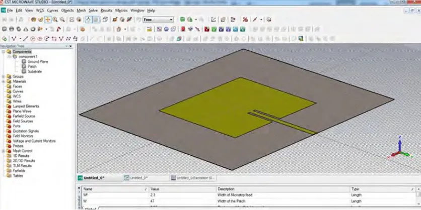
2.1 CST Microwave Studio
4
Figure 2.1: Software of CST Microwave Studio
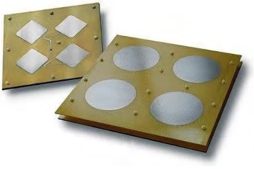
2.2 Material Substrate (FR-4)
5
[image:20.612.114.542.370.585.2]Figure 2.2: FR-4 substrate layout [2]
Table 2.1: Parameter for FR-4 substrate [2]
Parameter Value
Dielectric constant 4.36
Loss tangent 0.013
Water absorption < 0.25%
Tensile strength < 310 mPa
Volume resistivity 8 x 10⁷ Mohm cm
Surface resistivity 2 x 10⁵ Mohm
Breakdown voltage 55kV
Peel strength 9N/nm
6
2.3 Antenna
Antenna is one of the critical components in any wireless communication system. The word ‘antenna’ is derived from Latin word ‘antemna.” Since the first demonstration of wireless technology by Heinrich Hertz and its first application in practical radio communication by Guglielmo Marconi, the antenna has been a key building block in the construction of every wireless communication system. IEEE defines an antenna as “a part of a transmitting or receiving system that is designed to radiate or receive electromagnetic waves” [3].
2.3.1 Wire Antenna
[image:21.612.222.436.419.606.2]This is the basic type of an antenna as shown in Figure 2.3 are widely used on top of the buildings, automobiles, ships and spacecraft. This antenna is made into different shape such as a straight wire (dipole), loop and helix.
7
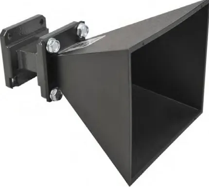
2.3.2 Aperture Antenna
[image:22.612.221.436.232.427.2]This antenna as shown in Figure 2.4 is in the form of a slot or aperture in a metal plate and commonly used at higher frequencies (3-30 GHz). Typical examples are slotted waveguide antenna and horn antenna. These antennas are very useful for aircraft and spacecraft applications, because they can be conveniently flush mounted on the surface of the aircraft or spacecraft.
8
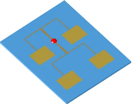
2.3.3 Printed Antenna
[image:23.612.205.460.295.465.2]A printed antenna as in Figure 2.5 is fabricated using standard photolithography technique. The most common version of printed antenna is microstrip antenna, which consists of a metallic patch above a ground plane. The shape and size of patch determine the frequency of operation of the antenna and its performance. This antenna is more popular because of their low cost and ease of fabrication, and easy integration with circuit technology, and are conformal to planar and non-planar surfaces. This antenna can be easily mounted on the surface of aircrafts, spacecraft, satellites, missiles and even on handheld mobile devices.
9
2.3.4 Array Antenna
[image:24.612.223.439.276.443.2]In an array antenna, several radiators separated from each other are geometrically arranged to give desired radiation characteristics that are not possible to achieve with a single independent radiating element. The arrangement of array elements is such that radiation from individual elements adds up to give the maximum radiation in a particular direction or directions and minimum radiation in other directions. An example of array antenna is shown in Figure 2.6.
![Figure 2.2: FR-4 substrate layout [2]](https://thumb-us.123doks.com/thumbv2/123dok_us/131512.12678/20.612.122.540.70.261/figure-fr-substrate-layout.webp)