WELDABILITY AND HEAT AFFECTED ZONE (HAZ)
EVALUATION FOR HIGH
ENERGY RATE JOINING OF THERMOPLASTIC
COMPOSITES USING MICROWAVES
H S Ku 1, E Siores 2 and J A R Ball 3
1,3
Faculty of Engineering and Surveying, University of Southern Queensland, West Street, Toowoomba, 4350, Australia.
2
School of Mechanical and Manufacturing Engineering, Swinburne University of Technology,
PO Box 218, Hawthorn, Melbourne, 3122, Australia.
SUMMARY: Industrial microwave technology for processing polymers and polymer based composites is currently in a state of considerable flux. This paper extends the applications horizon of microwaves in the area of reinforced thermoplastic composites joining, and places emphasis on the development of equipment and facilities aiming at maximising bond quality. It discusses the microwave facility used, including a 0.8 kW variable control power generator operating at 2.45 GHz, waveguide and a tuning piston designed for obtaining a standing wave at the seam of the butted and lapped test pieces. The effect of power input and cycle time on the heat affected zone is detailed together with the underlying principles of test piece material interactions with electromagnetic field. The process of autogenous joining of 33% by weight of random glass fibre reinforced nylon 66, polystyrene (PS) and low density polyethylene (LDPE) as well as 23.3 % by weight of carbon fibre reinforced PS thermoplastic composites is mentioned together with developments using filler materials, or primers in the heterogenous joining mode. The weldability dependence on the dielectric loss tangent of these materials is also described.
KEYWORDS: complex relative permitivity, loss tangent, fibre-reinforced thermoplastic composites, microwave and peripheral facilities, short-circuit plunger, butted test pieces.
INTRODUCTION
cons of the above processes [2] were fully discussed and the frequency range [5] used in the high-frequency welding was 3 to 40 MHz which is in the radio frequency range. However, three papers on microwaves joining of thermoplastic composites [3][6][7] have appeared. The merits [3] of employing microwaves in joining thermoplastics composites include having a clean and reliable interface at the joints and fast joining time with minimum destruction of the properties of the bulk materials. Limitations encountered in other processes are avoided.
The prototype equipment used for the study is shown in figure 1. The microwaves generated from the magnetron are guided through WR340 waveguide to the test pieces. Avoiding radiation leakage is of primary concern and the welding process is enclosed within a microwave oven cavity so that microwaves will not radiate to the environment. Other possible risks of using the test rig and the materials are studied as well.
MICROWAVE AND PERIPHERAL FACILITIES
Equipment is built around a modified commercial microwave oven. The two magnetrons were removed from the original locations and one of them (0.8 kW) is relocated onto the top of the oven cavity via a piece of WR340 waveguide. Another piece of waveguide with slits opened for positioning the test pieces is placed upright in the oven cavity so as to avoid hazardous radiation. The upper end was fitted with a flange connected to the magnetron mounted on top of the oven. The lower end is similarly attached to an additional length of waveguide containing a shorting plunger.
MAGNETRON
COMMERICAL OVEN
WAVEGUIDE
MOVEABLE PLUNGER
WAVEGUIDE SLIT
TEST PIECE
323 1109
110
L
182 90
INCIDENT WAVES
Figure 1. Microwave Facilities Configuration Figure 2. Stationary Wave in Waveguide
With reference to figure 1, the incident waves are generated by the magnetron. They travel downwards through three sections of WR340 waveguide and interact with the test pieces located in the second section before being reflected back by the top face of the adjustable plunger. The plunger was designed and manufactured to have a sliding fit contact with the waveguide. The interaction between the incident and the reflected waves sets up a standing wave [8] and it is desirable that the maximum electric field occurs at the seam of the butted and lapped test pieces. This was achieved by adjusting the moveable piston so that its top face is an odd multiple of λg/4 from the centre of the slit; where λg is the wavelength within
the waveguide.
SHORT-CIRCUIT PLUNGER AND ITS DIMENSIONS
The relationship between the wavelength within the guide, λg and the free space wavelength,
λο is as follows [8] :
where a is the larger of the internal dimension of the waveguide and is in mm.
Using, the relationship v = f λο (2)
λο = (3x10¹¹)/(2.45x109) = 122.45 mm
For the waveguide used, WR340, a = 86.36 mm and b = 43.18 mm, therefore, λg = 173.63 mm and λg/4 = 43.408 mm.
Referring to figure 2, the distance between the centre of the slit and the top face of the plunger, l, was initially 286 mm. To create maximum electric field l has to be varied so that l
= n x λg/4 and n is an odd integer. If n = 7 is chosen then l = 7 x λg/4 = 7 x 43.408 mm =
303.9 mm. The distance, l, can be varied by adjusting the plunger up and down by rotating the knob at the bottom of the plunger. Hence, in order to have a maximum of electric field at the specimen, the plunger is adjusted by 303.9 mm - 286 mm = 17.9 mm in the downward direction. This is the maximum electric field when the test pieces are at room temperature and this setting formed part of the initial set-up.
Leakage of power past the plunger is expected because of the sliding fit, and measures must be taken to prevent it. Any leakage is minimised by using a non-contact method to produce an apparent short circuit at the front face of the plunger. The actual point of contact is arranged to be at a point where the current is effectively zero. This is accomplished as shown in figure 3. At a distance of λg/4 from the top face of the piston [8], the traverse electric field,
Ehas a maximum value and the traverse magnetic field His zero. Thus the ratio of traverse components E/His infinite at this point and hence the input wave impedance of a λg/4 length
of waveguide closed at its far end is infinite. Similarly, the input impedance of a λg/2 length
is zero. In practice, neither the infinite nor the zero values can be attained but it is convenient to assume so in practice.
110 10
22
A
B
C
b
x d1
d2
b2 b1
LOSSY MATERIAL
ADJUSTING ROD CONTACT POINT
Figure 3. Moveable Plunger Figure 4. Non-contact Type Adjustable Short Circuit in Waveguide
In figure 3, the part ABC is regarded as a narrow waveguide of length λg/2 short-circuited at
C and folded at its centre, B. Thus its input impedance at A is zero, and there is an equivalent short-circuit at the other side of the sliding fit. The piston therefore appears as a continuous short-circuit across the waveguide. The sliding contact occurs at B, which is λg/4 from the
end, point C. At point B, the impedance is high with small magnetic field [8] and the current is therefore small and radiation leakage through the sliding contact is therefore extremely small. Variations in contact resistance with movement of piston are of little importance. Here actual physical short-circuits are replaced by virtual short-circuits and the physical contact made at a place where poor contact is not critical.
An example [9] for the dimensions of the moveable plunger is shown in figure 4, in which, b = 20 mm, b1 = 0.6 mm b2 = 4.0 mm.
Therefore in WR340, when b = 43.18 mm,
Since the plunger has a sliding contact with the waveguide, the clearance between the two is
made to be 0.5 mm. The angle of 45o was chosen for convenience of manufacture. The
dimensions of the plunger are shown in figure 5.
ANTTENNA POWER
METER
COAXIAL POWER SENSOR
40.58 43.18
86.36 8.64
45.0░
43.41 43.41
5 10
M10
255
110 5
M40 20
SIDE VIEW
FRONT VIEW
Figure 5. Dimensions of the Moveable Plunger Figure 6. Set-up for Measuring Leakage
RISK ASSESSMENT
Of the risks involved in this research, radiation leakage from the equipment may be by far the most worrying to people nearby. Careful measures have been taken to cope with the problem. First, the magnetron is enclosed in a metal case on top of the microwave oven cavity enclosure so that microwaves can only travel downwards to and through the three sections of the waveguide to the top face (reflector) of the plunger. Virtually no radiation can leak through the case to the surroundings. Power leakage is expected and will be most serious through the slits into which the test pieces are inserted, but it does not propagate to the environment because it is contained inside the enclosure of the microwave oven cavity. Another possible leakage point may be the sliding fit between the moveable plunger and its sleeve as shown in figure 3, but the problem has been minimised by the non-contacting short circuit technique described previously. The end of the plunger waveguide is also covered up by a metal plate and radiation leakage to the surrounding is virtually zero. However, in order to check that the equipment complies with the recommended exposure limit [10] of 10
mW/cm2, measurements of radiation leakage were made using power meter, power sensor
and an antenna. A coaxial to waveguide (WR 340) adaptor was used as the antenna. The set-up is shown in figure 6. Measurements were taken at a distance of one (1) metre radius around the equipment, where an operator usually stands and that distance also satisfies the far-field distance [11] requirement of the antenna of 120 mm. In all positions, the power leakage was much less than 10 mW/cm 2.
The glass fibre (GF) and carbon fibre (CF) filaments are embedded in the polymers and hence all the possible risks [12][13][14] associated with them do not apply in this case.
bond on contact. Breathing in its vapour has to be avoided. Goggles and protective gloves have to be worn when using.
The next item to be discussed is the GF reinforced (33%) nylon 66; no adverse health effects should occur [17] if the product is handled in accordance with the product label. The test pieces are injection-moulded products and are not granules so they carry none of the risks [17] associated with granules. The material is combustible but has certain self-extinguishing properties [17]. The decomposed products include ammonia and carbon monoxide, so exposure to it must be in accordance with the National Occupational Health and Safety Commission [17]. The study was therefore carried out in a ventilated area. The next material to be mentioned is polystyrene (PS). The test pieces are moulded products and the risks [18] inherited by the granules do not apply here. The polymer will burn [18] when supplied with sufficient heat and oxygen and will emit toxic fumes when being burned with insufficient oxygen. The test area was therefore well ventilated. The last item to be discussed is low density polyethylene (LDPE), which will burn [19] in the presence of extreme heat and oxygen. A powder foam fire extinguisher is readily available for use if it catches fire.
MATERIALS MICROWAVES INTERACTION CONSIDERATIONS
High energy rate welding of thermoplastic composites using microwave was studied because it was believed that the microwave/materials interactions of some of thermoplastic composites with and without fillers will favour the process. The material properties of greatest importance [20] in microwave processing of a dielectric are the complex relative permittivity ε = ε′ - jε″,and the loss tangent, tanδ = ε″/ ε′. The real part of the permittivity, ε′, sometimes called the dielectric constant, mostly determine how much of the incident energy is reflected at the air-sample interface, and how much is absorbed. The most important property in microwave processing is the loss tangent, tan δ, which predicts the ability of the material to convert the absorbed energy into heat. For optimum microwave energy coupling, a moderate value of ε′, to enable adequate penetration, should be combined with high values of ε″ and tan δ, to convert microwave energy into thermal energy. In a material with a very high loss tangent, the microwave energy density will reduce with distance of penetration into the material. This phenomenon is known as the skin effect. For a material having a polar molecule eg water, the real and imaginary parts of the permittivity vary with frequency as shown in figure 7. Because of the skin effect, it may not be possible to work at the relaxation frequency. The 2.45 GHz frequency was chosen because it seems [21] that it has been the most popular choice for property measurement and the magnetrons for that frequency are most readily available.
MAGNITUDE
FREQUENCY(GHz)
REAL PERMITTIVITY
2.45 17
IMAGINARY PERMITIVIT
RELAXATION FREQUENCY
20 40
152 43.18
TE MODE CAVITY
10 CLAMP
SPRING
ALUMINUM BLOCK
INTERFACE WAVEGUIDE
SECTION A - A' SLIT TEST PIECE
MICROWAVE
A'
[image:5.595.71.269.605.730.2] [image:5.595.286.476.615.725.2]A
Random GF reinforced (33%) nylon 66 was chosen for the study because the loss tangent [22] of nylon 66 is high as compared with other commonly used thermoplastic materials. The composite is commercially available in Australia. Random GF reinforced (33%) LDPE was selected because there was a successful case [7] of welding the composite with HDPE as matrix using microwave energy and it was believed that LDPE will couple better to microwaves [20] as its cyrstallinity is lower than the HPDE. The composite is not readily available in the market and it was specially manufactured in Plastic and Rubber Technical Education Centre (PARTEC) in Brisbane, Australia. Polystyrene (PS) matrix was chosen because first, it is a common thermoplastic polymer matrix [23] and second, its loss tangent [22] is very near to that of LDPE and a comparison could be made later on. The random CF (23.3%) reinforced PS and the random GF (33%) reinforced PS were manufactured in PARTEC. In all cases, the length of the reinforcing fibre was 6 mm or less and the test pieces were injection-moulded to shape. However, typical lengths [24] of fibres used in reinforced injection moulding materials were 0.8 to 25 mm.
TEST PIECE MICROWAVE INTERACTION RESULTS
[image:6.595.73.458.671.781.2]The two mirror image test pieces were cut using a band saw from a standard tensile test piece for composite materials. They were then located, spring loaded and clamped as shown in figure 8. The spring was made to push the two pieces when the interface was melted by microwave energy and weld them together. The spring force was kept to be about 10 N. With the exception of the CF reinforced PS, the test pieces gave no reaction to microwaves without filler. Graphite powder was then sprayed onto the interface of the test pieces of composites other than CF reinforced PS. The powder was made to stick to the interface by first smearing the latter with very small amount of one part adhesive. To enhance microwave absorption, the side faces of the test pieces, up to 20 mm from the interface were also sprayed with graphite powder. The power used was 240 W and the duration of exposure was 4 seconds for test pieces for all composites. During the first few welding trials, welding sometimes took place between the test pieces but at most of the time, the spring forced the test pieces to slip over each other due to the small interface area ( 3 x 10 mm2). Even if they did weld, the bond strength obtained was very weak relative to the strength of the parent material.
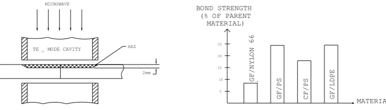
To overcome the problem, the interface was roughened by rubbing it against a piece of coarse, grade 80, emery paper. The test pieces of all kinds of composites were then joined together by a small amount of one part adhesive. Graphite powder was again sprayed onto the side faces of the three types of materials as in the previous case. The composite test pieces were welded with 240 W power and 4 seconds of exposure time. The heat affected zone (HAZ) for the CF reinforced PS was the part of the test pieces contained in the waveguide ie 21.5 mm from both sides of the interface and was on the upper part of them as shown in figure 9. When the exposure time was increased to 5 seconds, the spring forced the two pieces to bend to a vee- shape with the lower part of the joint being broken.
2mm MICROWAVE
HAZ TE10MODE CAVITY
Figure 9. HAZ for GF/PS Figure 10. Bond Strength of the Weld
The test pieces of other materials had 20 mm from both sides of the interface as their HAZs and this was totally due to the amount of graphite powder sprayed. When the exposure time was increased to 5 seconds, the graphite powder flashed and burnt the test pieces. The graphite powder was over-heated and glowed as a result of ‘thermal runaway’ due to localised heating of the test pieces. Tensile tests were carried out with the successfully welded test pieces and it was found that the bond strengths of all materials ranged from 8.5 % to 24.3% of those of the parent materials. The results are shown in figure 10.
Shimadzu tensile testing machine was used for the test. A load range of 2000 N and a load rate of 600 N per minute were selected for the test. After being tensile-tested, the interfaces of the broken test pieces were investigated and the adhesive on the interface was ground away by a tool grinder. In PS/GF test pieces, black marks were observed on the grey interface and were estimated to occupy up to 45% of the interface area. The marks might be burning marks and looked similar to those found on the interface of the same material after the material was sawn using a metallic bandsaw. After removing several thin layers of the interface, the marks still appeared and might be as thick as 2 mm and it was deduced that the marks were left behind after the burning and melting of the composite and that welding of the material did happen but only up to 45% of the interface area. If this were taken into account, it could be argued that the bond strength of the welded part was up to 54% of the parent material. However, it was difficult to locate similar black marks on the same position in the case of welded nylon 66/GF test pieces because the base material was black. Similar black marks could also be traced with LDPE/GF test pieces and the corrected bond strength of the weld would be up to 48% of the parent material.
700
600
500
400
300
200
BOND STRENGTH (N)
EXPOSURE TIME (MINUTES
FILLER
RUBBER BAND
3 20
20
20
RUBBER BAND 400W
800W
5 6
CURED AT AMBIENT CONDITIONS
1 2 3 4
Figure 11. Test Pieces with Lap Joints Figure 12. Bond Strength of GF/PS and Five Minute Two Part Adhesives
of the test pieces cured by leaving them in ambient conditions for 16 hours [15] with and without the rubber band pressure were 611 N and 335 N respectively.
After tightening with rubber band, the two halves of the test pieces were positioned in the slot across the waveguide similar to the situation illustrated in figure 8 except they stood there themselves with no clamping. The test pieces were then exposed to two different power levels of 400W and 800W with varying time of microwave exposure. In all cases, only the parts smeared with filler were warmed or heated depending on the power level used and the time of microwave exposure. The test pieces were allowed to cool to room temperature or below 60oC [15] before being tensile tested to obtain maximum bond strength. The results are summarised in figure 12.
With reference to figure 12, it was found that with 400 W power level, peak bond strength was achieved by exposing the test pieces to microwave for 2 minutes; the bond strength at this exposure duration exceeded that obtained by ambient conditions (conventional) curing by 7% but the time required was a mere 0.2% of its counterpart. Between the duration of one and a half to four and a half minutes, the bond strengths of microwave cured filler were higher than those obtained by allowing the adhesive to set under ambient conditions. With a power level of 800 W, maximum bond strength was achieved when the exposure time was 45 seconds and it exceeded the still air cured bond strength by 8%, but the time required was only 0.08% of its counterpart. The lower bond strengths obtained, for test pieces exposed to microwaves for over 2 minutes and over 45 seconds for power levels of 400 W and 800 W respectively, may be due to over-cured of the adhesive.
With some exposure durations, the bond strengths were higher than those cured conventionally because the parent material might have melted and diffused into the primer or interface and this was reflected in the softening of the lapped area after it was just removed from the applicator and examined using low power microscopy. The HAZ seemed to be confined to the lapped area, which could be bent by hand easily and outside which the warming and heating effect of microwave energy could not be felt. The tensile tests revealed that sixty percent of the failures were due to the adhesive and took place at the joints. The remaining failures took place at the original materials (GF/PS), which had an average strength of 1423 N. With a power level of 400 W and exposure time of 2 minutes, the highest bond strength achieved was 720 N; while with a power level of 800 W and exposure time of 45 seconds, the peak bond strength obtained was 905 N and they were 18% and 48% respectively stronger than the test pieces cured in ambient conditions. The values of ‘18%’ and ‘48%’ reveal the importance of power level used and it can be argued that the higher the power level used, the more efficient is the processing method.
CONCLUSIONS
The equipment will be further developed to accommodate a directional coupler and adaptors for measuring the power consumed in joining the composite test pieces, thermopiles for monitoring the temperature at the interface during welding, two electric field probes, and two electric motors to drive the piston continuously so that maximum electric field can always be maintained at the point where the interface of the butted test pieces is, as the temperature of test pieces varies during welding. The shape of the test pieces will also be modified so that the areas of the interface will be larger to prevent slipping. This consists of using specially designed lap joint for tensile test piece. Impact tests will also be incorporated to the study. The number of types of materials to be tested will be increased to include CF and GF reinforced thermoplastic polyutherane (TPUR) as the plastic contains hydroxyl and cyanate groups [20], which are reactive to microwave energy.
The potential benefits of the technology will be to speed up the replacement of thermosetting resins by advanced thermoplastic composites in the structural parts of aeronautical, military and recreational industries
REFERENCES
1. Siores, E., “Microwave Technology for Welding and Joining”, Materials World, Vol. 2, No. 10, 1994, p.526.
2. Schwartz, M.M., Composite Materials Handbook, McGraw-Hill, 2nd edition, 1992, pp.6.55-6.
3. Varadan, V.K. and Varadan, V.V., “Microwave Joining and Repair of Composite Materials”, Polymer Engineering and Science, Mid-April, Vol. 31, No. 7, 1991, pp. 470 - 486.
4. Partridge, I.K., Advanced Composites, Elsevier Applied Science, 1989, pp. 44-6.
5. Schwartz, M.M., Joining of Composite-matrix materials, ASM International, 1995, p. 64.
6. Stokes, V.K., “Joining Methods for Plastics and Plastic Composites: An Overview”, Polymer Engineering and Science, Mid-October, Vol. 29, No. 19, 1989, pp.1310-24.
7. Wu, C.Y. and Benatar, A., “Microwave Joining of HDPE Using Conductive Polyaniline Composites”, Proceedings of Society of Plastics Engineers. 50th Annual Technical Conference, 1992, pp. 1771-4.
8. Glazier, E.V.D. and Lamont, H.R.L., Transmission and Propagation, The Services’ Textbook of Radio, Volume 5, London, Her Majesty’s Stationery Office, 1958, pp. 151-7, 174-151-7, 197 - 9.
9. Rizzi, P.A., Microwave Engineering Passive Circuits, Prentice Hall, 1988, pp. 320-1.
10. Jacques, T., Microwaves: Industrial, Scientific and Medical Applications, Artech House Inc., 1992, pp. 503, 558.
11. Balanis, C.A., Antenna Theory, Analysis and Design, John Wiley & Sons Inc., 2nd ed., 1992, pp. 32-4, 58-9.
13. ACI Fibreglass, Material Safety Data Sheet (MSDS) for fibreglass, 1987, pp. 1-2.
14. Gougeon Brothers, Inc., MSDS for graphite fibres, undated, pp. 1-5.
15. Selleys Araldite, five minute epoxy adhesive user instructions, Selleys Chemical Compay Pty. Limited.
16. Selleys Fix ‘n’ Go, Supa Glue user instructions, Selleys Chemical Compay Pty. Limited.
17. ICI Plastics, MSDS for GF reinforced (33%) nylon 66, undated, pp. 1 -5.
18. Dow Chemical (Australia) Ltd., MSDS for polystyrene, 1994, pp. 1-4.
19. Kemcor, Australia, MSDS for LDPE, Kemcor Australia, 1995, pp.1 -4.
20. National Research Council, Microwave Processing of Materials , National Advisory Board Commission on Engineering and Technical Systems, National Research Council, 1994, p.7, 100, 105.
21. Metaxas, A.C. and Meredith, R.J., Industrial Microwave Heating, Peter Peregrinus Ltd., 1983, pp.43, 278.
22. Michaeli, W., Plastics Processing, Carl Hanser Verlag, Munich Vienna New York, 1995, pp. 189-90.
23. Shackelford, J.F., Introduction to Material Science for Engineers, 3rd., Macmillan, 1994, p.486.