Int. J. Electrochem. Sci., 14 (2019) 9132 – 9140, doi: 10.20964/2019.09.58
International Journal of
ELECTROCHEMICAL
SCIENCE
www.electrochemsci.org
Short Communication
Innovative Design and Fabrication of a Two−Dimensional Model
in Solid Oxide Fuel Cell Stack
Xuan–Vien Nguyen1,*, Guo–Bin Jung2, Shih–Hung Chan2
1 Department of Thermal Engineering, Ho Chi Minh City University of Technology and Education, Ho Chi Minh City, Viet Nam;
2 Department of Mechanical Engineering & Fuel Cell Center, Yuan Ze University, Taoyuan 320, Taiwan;
*E−mail: [email protected], [email protected] (XuanVien–Nguyen).
Received: 10April 2019 / Accepted: 9 July 2019 / Published: 5August 2019
In this study, an innovative two–dimensional solid oxide fuel cell (SOFC) stack based on a horizontal structure was developed. Planar anode–supported cells were utilized and integrated into a two– dimensional SOFC stack. The stack was designed to be operated in parallel as a large single cell and in series as a stack. The stack consisted of fuel and oxidant chambers, which allowed good heat transfer for preheating of the fuel inlet. These chambers inhibited the cooling effect of fuel (and oxidant) and thus improved the cell performance. Additionally, the two–dimensional SOFC stack model was designed for the perpendicular flows of fuel (and oxidant) directed to the electrode surfaces of the cells. This ensured the effective diffusion of fuel and oxidant between the anode and cathode surfaces, respectively. When the cells were connected in parallel, the two–dimensional stack functioned as a large single cell that generates a high current. When the cells were connected in series, the stack generated a high voltage. This innovative two–dimensional SOFC stack thus functioned as a large single cell and as a stack.
Keywords: Solid oxide fuel cell; Planar solid oxide fuel cell stack; Anode chamber; Cathode chamber.; SOFC cooling effect; Preheating
1. INTRODUCTION
Anode–supported solid oxide fuel cells (SOFC) are promising candidates for energy conversion systems. The solid oxide fuel cell technology represents for clean energy, reliable, and flexible power production. They have many advantages such as: the high conversion efficiency, the absence of combustion, and fuel flexibility which allows a variety of fuels, including those derived from renewable sources, to be used [1–5].
have many types with different sizes, shapes, materials, and power ranges, the methods to connect single cells into a stack can mainly be classified as bipolar and planar designs [6–9]. The fundamental concept of solid oxide fuel cell stack is a bipolar design, where two adjacent single cells use one bipolar plate that supplies fuel for one cell’s anode and oxidant for the other’s cathode and also play as current collector [10–13]. The bipolar designs in solid oxide fuel cell stack have the advantages of lower internal resistance and higher power. However, the conventional design complicated structure and higher material requirements restrict its applications. Stack design with two–dimensional model provides a better integration with applications.
The single cell and stack apparatus for solid oxide fuel cell has been developed. A single cell module has a cell with a fuel electrode, an electrolyte, and an air electrode. Two or four opposite sides of the cell are bent downward to form an electrode–supporting structure or a self–supporting structure having a reversed U–shaped cross–section. In the solid oxide fuel cell stack structure and the electrode–supporting or self–supporting structure, single cells are tightly stacked on a separate plate while they are held with sealant. In this invention, the fuel and oxidant are prevented from mixing by the sealant structure [14–18].
In previous studies, the solid oxide fuel cell systems were operated in higher temperature that improved its performance. However, the temperature distribution is one of the most important elements within the SOFC operation [19]. Several previous works examined the effects of the inlet fuel and oxidant temperature on the cell performance due to electrochemical reactions of carbon monoxide and hydrogen. It indicated that the total output power at higher inlet temperature is greater than the total output power at lower inlet temperature [20,21]. Marius Dillig developed a model to investigate the thermal effects of heat pipes system on the interconnector of planar SOC stacks. The results showed a respect to the possible benefits for stacks of different cell size, in particular regarding internal heat reusing and air ratios reducing [22].
In the present study, we developed a two–dimensional model for solid oxide fuel cell stack. When the cells are connected in parallel, this two–dimensional stack can function as a large single cell that generates a high current. When the cells are connected in series, the stack can generate a higher voltage. Therefore, this innovative two–dimensional SOFC stack functioned as a large single cell and as a stack. It is potentially a simpler in design, less costly than the traditional stack design, and flexible enough that modules of such two–dimensional stacks could, for example, be plated on hot walls where waste heat recovery is desired.
2. EXPERIMENTAL
2.1. Cell Fabrication
To manufacture the anode of the SOFC cell, ESL porous anode, functional anode, and electrolyte tapes were cut into multiple 70 mm × 70 mm sheets. Each unit cell is composed of three layers of the porous anode and one layer each of the functional anode and electrolyte sheet. Porous anode tape of 180 µm thickness and functional anode tape of 20 µm thickness were blended with NiO/YSZ ratio of 30 wt%/70 wt%. The electrolyte tape (18 µm thickness) is itself composed of 8 mol% YSZ. Three different material tapes were stacked respectively. Then, the stack was compressed under 230 kg cm-2 pressure load at 75 °C temperature and were maintained for 20 min. The anode sample was then allowed to cool at room temperature. The dried sample was cosintered at 1400 ºC for 5 h. A single SOFC cell unit was constructed on the sintered bilayer by coating a layer of cathode paste (La0.65Sr0.3MnO3) on the anode sample surface followed by sintering at 1200 ºC for 2 h [27,28].
2.2. Two–Dimensional SOFC Stack Design
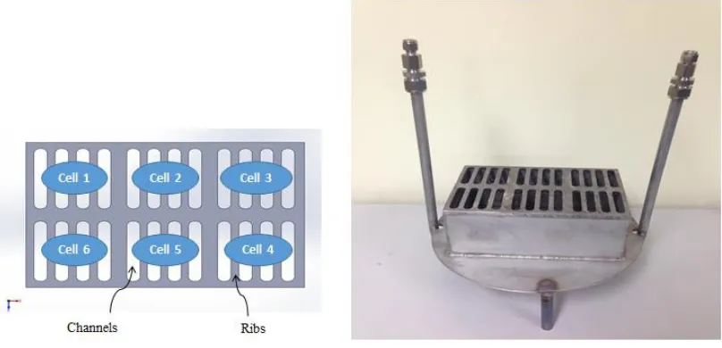
A two–dimensional SOFC stack module was designed to be operated in parallel with six cells as a large single cell and in series as a stack. As shown in Fig. 1, the device has six cells with an effective area of 50 mm × 50 mm on a horizontal surface. When the cells were connected in parallel, the stack functioned as a large single cell that generates a high current.
[image:3.596.97.501.547.742.2]
Figure 2. Schema of fuel and oxidant chambers.
[image:4.596.107.490.71.285.2]When the cells were connected in series, the stack generated a high voltage. The device consists of fuel and oxidant chambers that, for example, when placed on hot walls for heat recovery, allow heat transfer process to improve the temperatures of the fuel and oxidant inlet. The SOFC stack was avoided the cooling effect and thus improve output power of cell. The oxidant chamber was designed with a six–hole outlet with one hole toward each cell. These holes increase the uniformity of oxidant contribution (as shown in Fig. 2). Unlike the parallel–flow in conventional planar stack design, the two–dimensional SOFC stack model was designed with perpendicular flows of fuel and oxidant directed to the surfaces of the electrodes. The perpendicular flows ensure effective diffusion of fuel and oxidant toward the electrode surfaces. Its typical material and geometric parameters are shown in Table 1.
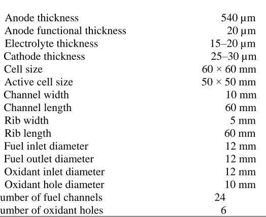
Table 1. Material and geometric parameters
Anode thickness 540 µm Anode functional thickness 20 µm
Electrolyte thickness 15–20 µm Cathode thickness 25–30 µm Cell size 60 × 60 mm Active cell size 50 × 50 mm Channel width 10 mm Channel length 60 mm Rib width 5 mm Rib length 60 mm Fuel inlet diameter 12 mm Fuel outlet diameter 12 mm Oxidant inlet diameter 12 mm Oxidant hole diameter 10 mm Number of fuel channels 24 Number of oxidant holes 6
[image:4.596.79.341.550.764.2]
2.3. Interconnect Design
(a) (b)
Figure 3. Schema of interconnect construction of the SOFC stack: (a) traditional stack design; (b) two–dimensional stack design.
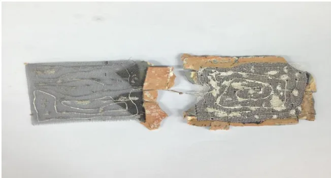
Figure 3 shows a schematic illustration of the interconnect configuration used for tests on the traditional and two–dimensional SOFC stacks. As shown in Fig. 3a, the traditional stack cells were sandwiched between current–collector plates. Parallel channels in each of the plates ensured an even distribution of the gases over the cell in cross–flow mode. The interconnect plates were inserted between the cells. Thus, one side of the plates faced a cathode current collector and the other side faced an anode current collector. In the two–dimensional interconnect design (Fig. 3b), the cells were connected in series by a much less costly current collector mesh in lieu of the traditional interconnect plates. An interconnect couple was fabricated from two different collector meshes and connected by using a collector wire [29]. The fabricated interconnect of the two cells in a two–dimensional model for SOFC stack is shown in Fig. 4.
[image:5.596.60.512.119.299.2] [image:5.596.134.460.560.736.2]
2.4. Testing
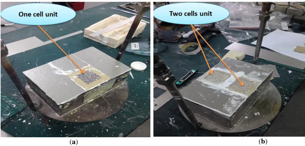
The two–dimensional SOFC stack was designed to be operated with six cells. In potential applications of such a design in developing countries where waste heat is more plentiful, the two– dimensional six–cell stack could be envisioned as an elementary module and such modules could be more easily placed in contact with hot walls where waste heat recovery is desired. In the present study, we used this six–cell module to test it’s one and two cells in details. Before all the six cells were assembled in the stack, tests were performed on a single cell situated in the middle of the stack as shown in Fig. 5a. To obtain sufficient contact between the electrodes and the electronic devices, Ni mesh was used on the anode and Ag mesh was used on the cathode side. Two Ag wires were connected to each mesh to play as potential and current probes, respectively. The single cell performance was tested at 750 °C. The temperature was slowly increased from room temperature to 750 °C for electrodes pretreatment. At 750 °C, the flow rate of hydrogen was 200 ml min-1 (with 3% H2O) on the anode, and the flow rate of air was 300 ml min-1 on the cathode side.
The two–cell stack as shown in Fig. 5b was then operated and tested under conditions similar to those of the unit cell, namely, hydrogen with 3% H2O was used as fuel and air as oxidant. The flow rate of hydrogen was 300 ml min-1 (with 3% H2O) on the anode and that of air was 400 ml min-1 on the cathode side.
(a) (b)
[image:6.596.49.552.401.643.2]
3. RESULTS AND DISCUSSION
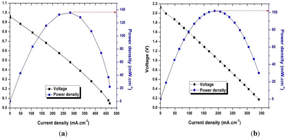
The power curve of the two–dimensional stack model is shown in Fig. 6a. The single cell was tested at 750 °C. At 750 °C, the open–circuit voltage was around 1.0 V, and the power density was 136 mW cm-2 and a output power of about 3.4 W. The performance of the two–cell stack are shown in Fig. 6b. The two–cell stack was operated under operating conditions similar to those of the unit cell. As shown in the Fig. 6b, the open–circuit voltage of the two–cell stack was 2.12 V. This showed that the open–circuit voltage of each unit cell was about 1.06 V, which is comparable to that of the single cell performance. The open–circuit voltage for the stack is almost similar to the theoretical value, suggesting that all of the stack components in such design were working properly, fuel leakage and dense electrolyte were absent, electrical potential through the cells was optimal, and the stack housing was tight. At 750 °C, the power density was 102 mW cm-2 at a stack potential of 1.09 V (0.545 V per cell), and the output power of two–cell stack was about 5.1 W. In previous works, Jung developed two–dimensional model for DMFC stack. The result showed that the maximum power density of the three–cell stack was 11.2 mW cm-2, and its total output is about 280 mW [30]. Kim fabricated a multi– cell arrayed planar SOFC stack device which was based on two–dimensional model of each cell unit connection. The results showed that the 4–cell and 2–cell array systems were operated successfully. The power densities were 460 mW cm-2 and 450 mW cm-2 at 750 ºC, respectively [31]. However, Kim just did on an anode–supported planar SOFCs with large active area (100 mm × 100 mm) by parallel connection.
In this study, the power density of the two–cell stack is less than that of the single cell. This is mainly attributed to the somewhat inconsistent performance of each of the two cells. The cell fabrication skill effects on the cell performance. Currently, we use available commercial materials to manually fabricate the cells and as such to yield consistent cells is a challenge. Nevertheless, this study shows the feasibility of two–dimensional model for SOFC stack design with planar anode–supported cells.
[image:7.596.65.526.513.739.2]
4. CONCLUSIONS
In this study, we developed an innovative two–dimensional model for SOFC stack with planar anode–supported cells. Two–cell stack made of a 50 mm × 50 mm unit cell in active area, was operated successfully. The cell potential is around 1.0 V. The power density is 136 mW cm-2 at a potential of 0.48 V, and its total output power at 750 °C is about 3.4 W. The OCV of the two–cell stack is 2.12 V. This shows that the potential of each unit cell is about 1.06 V at 750 °C, which is similar to that from the single cell test. The power density of the two–cell stack isn’t as good as the single cell, possibly due to inconsistent cells fabricated manually in the lab. This innovative two–dimensional model functions as a single cell and as a stack. When the cells are connected in parallel, this two– dimensional stack functions as a large single cell that generates a high current. When the cells are connected in series, the stack functions as a stack that generates high voltage. With this feasibility study, in future work, all the six cells in the current 6–cell design will be connected in parallel to form a large single cell, equivalent to a 10 cm × 15 cm unit cell in active area. They will also be connected in series to form a six–cell stack. The result of the tests will be reported in the later work.
ACKNOWLEDGMENTS
The authors gratefully thank the Ho Chi Minh City University of Technology and Education, Fuel Cell Center at Yuan Ze University for the support.
CONFLICTS OF INTEREST
The authors declare no conflict of interest.
References
1. Q.M. Nguyen, J. Am. Ceram. Soc., 76 (1993) 563.
2. J.M. AnduJar and F. Segura, Fuel cells, Renew. and Sus. Energy Reviews, 13 (2009) 2309.
3. G.B. Jung, L.H. Fang, M.J. Chiou , X.V. Nguyen , A. Su , W.T. Lee , S.W. Chang, IC. Kao and J.W. Yu, Energies, 7 (2014) 3922.
4. X.V. Nguyen , C.T. Chang , G.B. Jung, S.H. Chan, W.C.W. Huang, K.J. Hsiao, W.T. Lee , S.W. Chang and IC. Kao, Energies, 9 (2016) 701.
5. X.V. Nguyen , C.T. Chang , G.B. Jung, S.H. Chan, W.T. Lee , S.W. Chang and IC. Kao, Int. J. Hydrogen Energy, 41 (2016) 21812.
6. R. Jiang and D. Chu, J. Power Sources, 93 (2001) 25.
7. J. Li, Z. Bai and E. Croiset, J. Power Sources, 333 (2016) 164.
8. Y. Mollayi Barzi, A. Raoufi and H. Lari, Int. J. Hydrogen Energy, 35 (2010) 9468. 9. J. Laurencin, F. Lefebvre Joud and G. Delette, J. Power Sources, 177 (2008) 355. 10.J. Scholta, B. Rohland, V. Trapp and U. Focken, J. Power Sources, 84 (1999) 231. 11.M. Canavar and Y. Kaplan, Int. J. Hydrogen Energy, 40 (2015) 7829.
12.L. Jin, W. Guan, J. Niu, X. Ma and W.G. Wang, J. Power Sources, 240 (2013) 796. 13.G. Wang, W. Guan, F. Miao and W.G. Wang, Int. J. Hydrogen Energy, 39 (2014) 17836.
14.S.Y. Young, H.H. Young and T.K. Kang, Single cell and stack structure for solid oxide fuel cell stacks (2005), United States patent US6864009.
16.J. Wang, Int. J. Hydrogen Energy, 33 (2008) 6339. 17.J. Wang, Int. J. Hydrogen Energy, 35 (2010) 5498.
18.T. Dey, P.C. Ghosh, D. Singdeo and M. Bose, Int. J. Hydrogen Energy, 36 (2011) 9967.
19.E. Vakouftsi, G.E. Marnellos, C. Athanasiou and F. Coutelieris, Sol. State Ionics, 192 (2011) 458. 20.J. Park, P. Li and J. Bae, Int. J. Hydrogen Energy, 37 (2012) 8532.
21.H. Djamel, A. Hafsia, Z. Bariza, B.M. Hocine and O. Kafia, Int. J. Hydrogen Energy, 38 (2013) 8575.
22.Marius Dillig, Thomas Plankenbühler and Jürgen Karl, J. Power Sourses, 373 (2018) 139. 23.C.M. Huang, S.S. Shy, H.H. Li and C.H. Lee, J. Power Sources,195 (2010) 6280.
24.X.V. Nguyen , C.T. Chang , G.B. Jung, S.H. Chan, C.C. Yeh, J.W. Yu and C.Y. Lee, Renewable Energy, 129 (2018) 806.
25.J.J. Yang, D. Yan, W. Huang, J. Li, J. Pu, B. Chi and L. Jian, Energy, 149 (2018) 903. 26.W.C. Tana, H. Iwai, M. Kishimoto and H. Yoshida, J. Power Sourses, 400 (2018) 135.
27.G.B. Jung, C.T. Chang, C.C. Yeh, X.V. Nguyen , S.H. Chan, C.Y. Lin, J.W. Yu, W.T.Lee, S.W. Chang and IC. Kao, Int. J. Hydrogen Energy, 41 (2016) 21802.
28.G.B. Jung, L.H. Fang, C.Y. Lin, X.V. Nguyen, C.C. Yeh and C.Y. Lee, Int. J. Electrochem. Sci., 10 (2015) 9089.
29.A. Heinzel, C. Hebling, M. Muller, M. Zedda and C. Muller, J. Power Sources, 105 (2002) 250. 30.G.B. Jung, F.B. Weng, A. Su, C.C. Chung, C.H. Tu and S.H. Chan, J. Fuel Cell Science and
Technology, 3 (2006) 8.
31.H. Kim, H.Y. Jung, H.G. Jung, J. Kim, J.H. Lee, H.W. Lee and H. Song, ECS Transactions, 7 (2007) 311.