UNIVERSITI TEKNIKAL MALAYSIA MELAKA
ENHANCE THE PERFORMANCE OF CONDENSER BY USING
EVAPORATIVE COOLING METHOD FOR SPLIT TYPE AIR
CONDITIONER
This report is submitted in accordance with requirement of the Universiti Teknikal Malaysia Melaka (UTeM) for the Bachelor of Engineering Technology
(Refrigeration & Air-Conditioning System) with Honours
By
KARTHIGEYAN A/L RAMAKRISHNAN B071210541
910410-08-5653
DECLARATION
I hereby, declared that this report entitled “Enhance the performance of condenser by using evaporative cooling method for split type air conditioner” is the results of my
own research except for quotes as cited in references.
Signature : ……….
Author’s Name : ……….
APPROVAL
This report is submitted to the Faculty of Engineering Technology of Universiti Teknikal Malaysia Melaka (UTeM) as a partial fulfillment of the requirements for the award of Bachelor of Mechanical Engineering Technology (Refrigeration & Air-Conditioning Systems) with Honours. The member of the supervisory is as follow:
i
ABSTRAK
ii
ABSTRACT
iii
DEDICATION
iv
ACKNOWLEDGEMENT
v
TABLE OF CONTENTS
ABSTRAK. ... i
ABSTRACT ... ii
DEDICATION ... iii
ACKNOWLEDGEMENT ... iv
TABLE OF CONTENTS ... v
LIST OF TABLES ... ix
LIST OF FIGURES ... x
LIST OF ABBREVATIONS, SYMBOLS AND NOMENCLATURES ... xii
CHAPTER 1: INTRODUCTION ... 1
1.1 Background of the Study ... 1
1.2 Problem Statements ... 2
1.3 Objectives of The Study ... 3
1.3.1 Main Objective: ... 3
1.3.2 Specific Objectives: ... 3
1.4 Work Scope of The Study ... 3
CHAPTER 2: LITERATURE REVIEW ... 5
2.1 Introduction ... 5
2.2 Performance of Air-cooled Condenser ... 5
2.3 Application of Evaporative Cooling for Air-cooled Condenser ... 6
2.4 Water Spray Mist Pre-Cooling System ... 8
2.5 Direct Evaporative Cooling (DEC) System ... 9
2.6 Evaporative Cooling Pad ... 10
2.7 Selection Criteria for Evaporative Cooling Pad ... 10
2.8 The Effect of Air Velocity and Cooling Pad Thickness ... 11
vi
2.10 Pressure Drop across the Cooling Pad ... 12
2.11 Water Evaporation from the Cooling Pad ... 12
2.12 Air Conditioner Condenser Fan Performance ... 13
2.13 Impact of Air Flow on Condensing Unit ... 14
2.14 Condenser Fan Sound Control ... 14
CHAPTER 3: METHODOLOGY ... 16
3.1 Introduction ... 16
3.2 Project Planning ... 16
3.3 Flowchart of The Project ... 17
3.4 Equipments and Materials ... 18
3.4.1 Split type air conditioner ... 18
3.4.2 Evaporative cooling pad ... 19
3.4.3 Water pump ... 19
3.4.4 Thermocouple ... 20
3.4.5 Pressure gauge ... 21
3.4.6 Clamp meter ... 21
3.4.7 Flaring and swaging tools ... 22
3.4.8 Copper tube cutter ... 23
3.4.9 Welding gas and torch ... 23
3.4.10 Accessories and fittings ... 24
3.4.11 Copper tubing ... 25
3.5 Designing the Model using Solidwork Software ... 26
3.5.1 Development of design ... 26
3.6 Development of the Project ... 29
3.7 Working Principle of the Project ... 32
vii
CHAPTER 4: RESULTS & DISCUSSIONS ... 34
4.1 Introduction ... 34
4.2 Specific Parameters Results ... 34
4.2.1 Sketching Pressure-Enthalpy Chart ... 36
4.3 Performance Analysis and Discussion ... 38
4.3.1 Effect of Ambient Temperature to the Coefficient of Performance of the System ... 38
4.3.2 Effect of Ambient Temperature to Cooling Effect of the System ... 39
4.3.3 Effect of Ambient Temperature to the Compressor Work ... 41
4.3.4 Effect of Ambient Temperature to the Electric Current Consumption of the System ... 42
4.3.5 Reduction of Condenser Inlet Air Temperature Using Evaporative Cooling Method ... 44
4.3.6 Discussion on the Performance Analysis ... 45
4.4 Water Evaporation Rate ... 46
4.4.1 Discussion on Water Evaporation Rate ... 47
CHAPTER 5: CONCLUSIONS & FUTURE WORK ... 49
5.1 Introduction ... 49
5.2 Summary of the Experimental Study ... 49
5.3 Conclusions ... 50
5.4 Recommendations ... 51
5.5 Limitation... 51
viii
APPENDIX A……….…...56
APPENDIX B………57
APPENDIX C………58
ix
LIST OF TABLES
Table 4.1: Experimental data for temperature at various ambient temperatures ... 35 Table 4.2: Experimental data for pressure at various ambient temperatures ... 36 Table 4.3: Enthalpy of R-22 refrigerant at various ambient temperatures ... 37 Table 4.4: Different of COP of the system between conventional and evaporative
cooling with the increase of ambient temperature ... 38 Table 4.5: Different of cooling effect between the conventional and evaporative
cooling with the increase of ambient temperature ... 40 Table 4.6: Comparison of compressor work between the conventional and
evaporative cooling with the increase of ambient temperature ... 41 Table 4.7: Comparison of electric current consumption between conventional and
x
LIST OF FIGURES
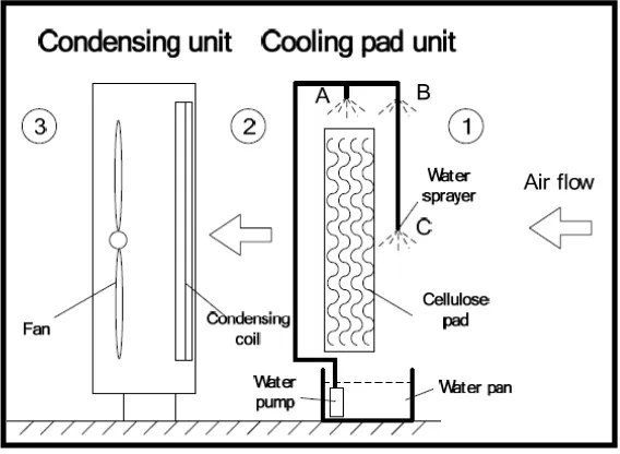
Figure 2.1: Schematic diagram of evaporative cooling system (Chaktranond and
Doungsong, 2010) ... 7
Figure 2.2: Schematic of the air-cooled chiller with water mist system (Jia Yang et al., 2012) ... 9
Figure 3.1: Flowchart of the project ... 17
Figure 3.2: Split type air conditioner (Model National) ... 18
Figure 3.3: Corrugated cellulose cooling pad ... 19
Figure 3.4: Submersible water pump ... 20
Figure 3.5: K-type two channel digital thermocouple ... 20
Figure 3.6: Bourdon pressure gauge ... 21
Figure 3.7: Digital clamp meter ... 22
Figure 3.8: Flaring and swaging tools ... 22
Figure 3.9: Copper tube cutter ... 23
Figure 3.10: Welding gas with torch ... 24
Figure 3.11: Accessories and fittings ... 24
Figure 3.12: Copper tubing ... 25
Figure 3.13: Model of condensing unit of split type air conditioner ... 26
Figure 3.14: Model of corrugated evaporative cooling pad ... 27
Figure 3.15: Complete model of the experimental study ... 28
Figure 3.16: Inside view of condensing unit ... 29
Figure 3.17: Condenser coil and Tee ... 29
Figure 3.18: Brazed Tee with access valve ... 30
Figure 3.19: Flaring process ... 30
Figure 3.20: Condensing unit with pressure gauge ... 31
Figure 3.21: Condensing unit and indoor unit of air conditioner ... 31
Figure 3.22: Vacuum process ... 32
Figure 3.23: Condensing unit retrofitted with evaporative cooling pad ... 32
Figure 4.1: Graph of coefficient of performance against ambient temperature ... 39
Figure 4.2: Graph of cooling effect against ambient temperature ... 40
xi
Figure 4.4: Comparison chart of electric current consumption against ambient
xii
LIST OF ABBREVATIONS, SYMBOLS AND
NOMENCLATURES
A - Ampere
ARI - Air-Conditioning and Refrigeration Institute COP - Coefficient of Performance
CTC - Condenser Temperature Control
CV - Conventional
DBT - Dry Bulb Temperature
DC - Direct Current
DEC - Direct Evaporative Cooling
EC - Evaporative Cooling
NDDCT - Natural Draft Dry Cooling Tower
OD - Outer Diameter
PVC - Polyvinyl Chloride
RH - Relative Humidity
1
CHAPTER 1
INTRODUCTION
1.1 Background of the Study
Nowadays, air conditioning is widely used during summer seasons and hot weather countries. There are many types of air conditioning systems are available in market. The most commonly used small tonnage air conditioning system at residential, offices, shops, small industries are window air conditioner and split air conditioner. But, the window air-conditioner is no more in market because of its some disadvantages such as high noise level, higher power consumption, difficulties in installation and etc. But, split type air-conditioner is currently much familiar than the window air conditioner due to some of its advantages. This split type air conditioner divided into two parts which is condensing unit normally known as outdoor unit located at the outside of the building and fan coil unit normally known as indoor unit located at the conditioned space.
2
consequently result in increase the power consumption because the pressure ratio becomes higher and the compressor is forced to work.
In this regard, to overcome the increase in temperature, a higher airflow rate is required by an air-cooled condenser for enhance its performance, and it sometimes causes some increase in sound level. So in general, by reducing the condenser temperature and increasing the capacity of cooling and heat rejection, COP of the system can be improved. The direct evaporative cooler is coupled with the air-cooled condenser for the purpose of reduce the ambient air temperature. The evaporative cooling pads are fixed at the upstream of the air cooled condenser and inject water on the cooling pad using water pump. The water flows down due to gravity and when the hot ambient air enter through the evaporative cooling pad, its temperature reduced before passes over the condenser coil to enhance the air cooled condenser performance of split type air conditioner, Luis Perez- Lombard, and collegues, (2008).
1.2 Problem Statements
An air-cooled condenser is mostly used in the split type air conditioner. Performance of the air cooled condenser depends on the ambient air temperature and the thermal stability fluctuates throughout the year especially in hot weather. When the ambient temperature increases thus, it will cause the pressure and temperature of the air cooled condenser increases. This will force the compressor to work under higher pressure ratio and consume more power. Sometimes the excessive pressure can cause the compressor trip. The performance can be improved by raising the air flow rate through the condenser coil but it will results in some noise problem. Luis Perez- Lombard, and colleagues, (2008), reported that 17% of the total global energy was consumed by air conditioning.
3
thus results in mixture of vapour and liquid refrigerant enters the expansion valve (capillary tube) consequently decreasing the coefficient of performance of the system. Whereas the experiment carried out by C. Chaktranond et al., (2010), reported that electrical power consumption increases by 4% when the condenser temperature increases every 1˚C.
1.3 Objectives of The Study
1.3.1 Main Objective:
To improve the performance of air-cooled condenser of split type air conditioner.
1.3.2 Specific Objectives:
I. To reduce the temperature of ambient air by using cellulose evaporative cooling pad before it passes over condenser coil.
II. To increase the coefficient of performance of the system by decreasing the condenser on-coil temperature using indirect evaporative cooling method. III. To reduce the energy consumption of the system by decreasing the
compressor work.
IV. To identify the relationship between ambient air temperature and COP of the air conditioning system.
1.4 Work Scope of The Study
4
system. Performance of air cooled condenser will be enhanced by decreasing the ambient air temperature by placing corrugated cellulose evaporative cooling pad injected with water at the upstream of the condenser. The ambient air temperature before and after passes the cooling pad will be measured using thermocouple.
5
CHAPTER 2
LITERATURE REVIEW
2.1 Introduction
This chapter will be mainly focused on the literature review regarding the enhancement of an air-cooled condenser of air conditioning and refrigeration systems. Many experiments have been done by the researchers to improve the performance of condenser by using several types of methods. There are some review related to the project were done such as the evaporative cooler coupled with air-cooled condenser, water mist system, direct evaporative cooling system, selection of evaporative cooling pad and optimization of the evaporative cooling pad thickness, effect of condenser air flow through the condenser coil, condenser fan performance and plain and finned tube performance. By review the relevant literature, it will help the author to understand the actual problem and able to conduct the experimental studies based on the literature have been done.
2.2 Performance of Air-cooled Condenser
6
to 4-6 ˚C beyond the wet-bulb temperature of ambient air. Because of this, a greater condenser pressure is needed by an air-cooled chillers compare to water-cooled chillers, which influence to consume more power by the compressor and less refrigeration capacity.
Thermal stability of an air-cooled condenser is based on the temperature of ambient air and it is not stable throughout the year. Due to higher ambient air temperature, the refrigerant flowing in the condenser coil unable to fully condense and enters the expansion valve with the mixture of liquid and vapour thus, results in decreasing of COP of the system. Tianwei Wang, Chenguang Sheng and Agwu Nnanna, (2014). An experimental study by Chow et al., (2002), reported that 1˚C increased on the on-coil temperature of the condenser results in decrease of COP of the system by around 3%. To improve the COP of the system, the ambient air temperature must decrease before it passes through the condenser coil.
2.3 Application of Evaporative Cooling for Air-cooled Condenser
Hajidavalloo, (2007), carried out an experiment to investigate the effect of evaporative cooling for a window air conditioner using two methods. First, the cellulose bound cardboard is used as an evaporative cooling pad and water is injected on the cooling pad and by small water pump to provide cooling effect to the condenser by evaporation of water. This method is known as indirect evaporative cooling. Whereas, another method is direct evaporative cooling which means, water is directly injected on the condenser coil. Although this method can increase the COP of the system, there are some side effects such as mineral deposits and corrosion on the condenser coil. By using the indirect evaporative cooling method, Hajidavalloo, (2007), reported that about 16% of energy consumption decreased and at the same time, about 55% increase in COP of the system.
7
condition, an indirect evaporative cooling system applied to packaged unit air conditioner and they are able to improve the cooling load up to 75% and consume 55% less electrical energy. Delfani Shahram, (2010). Zhang et al., (2000), carried out a study on the evaporative cooler permeated with corrugated holed aluminium foil and given relationship to estimate the performance, pressure drop and outlet air temperature of the cooler. They apply the relationship for estimate the enhancement of an air-cooled chiller by analyze the exit temperature of evaporative cooler with the performance curve of the chiller and conclude that the COP for chiller could be enhanced about 39%. An air-cooled chiller coupled with a direct evaporative cooler able to reduce 14.4% in power consumption and increase the refrigeration capacity about 4.6%. Yu and Chan, (2005).
[image:22.595.178.462.505.713.2]Chaktranond and Doungsong, (2010), carried out an experimental study on the residential size split type air conditioner’s condensing unit retrofitted with an indirect evaporative cooling system. The water injecting method on the evaporative cooling pad divided into two types which is water curtain and water spray. The evaporative cooling pad is placed in the upstream flow of air entering the condenser coil. The gap between the condenser coil and the evaporative cooling pad is 0.05m. By using this indirect evaporative cooling system, the ambient air temperature that entering the condenser coil could be reduced up to 3˚C and conclude that the ambient air temperature affects the system performances more than the relative humidity.
8
2.4 Water Spray Mist Pre-Cooling System
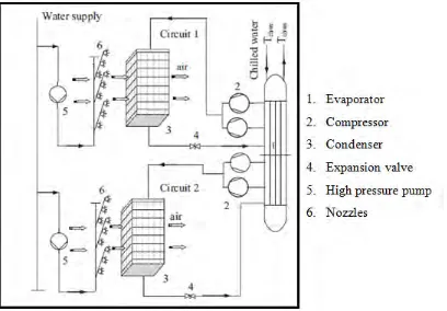
According Hsieh and Yao, (2006), the water spray mist cooling system with a tor or mesh material (WSMCST) is not a new concept because it have been applied in various types of industries, but not common in air conditioning and refrigeration system. This condenser performance enhancement method is differing from other method due to this system monitored in real-time and electronically controlled. This WSMCST system mainly consists of three subsystems such as water treatment and control unit, high pressure pulverization unit with atomization nozzles and the third is a specially manufactured microprocessor. An experimental study by Jia Yang et al., (2012), shows that the high pressure pump deliver water with 70 bar pressure and forced through a micro nozzle to create a mist of 10µm droplets to produce a cloud of very small water droplets. These droplets vaporized by the ambient air before get in the condenser coil and the ambient air temperature reduced follow by the adiabatic cooling process with constant specific enthalpy.
9
Figure 2.2: Schematic of the air-cooled chiller with water mist system (Jia Yang et al., 2012)
2.5 Direct Evaporative Cooling (DEC) System
Based on Camargo et al., (2005), induced processes of mass and heat transfer by using the water and air as working fluids is the working principal of evaporative cooling. It comprises, particularly, in evaporation of water, impelled by the transition of an air flow, thus results in lowering the temperature of the air. At the point water evaporates into the air, its temperature dropped down and consequently humidifying the air, this thermal process is called the adiabatic saturation and also known as the direct evaporative cooling (DEC). Ebinuma et al., (2002), study the operation principal of direct and indirect evaporative cooling systems by the development of mathematical equations of thermal exchanges, which allow finding the heat transfer
convection coefficient for primary and secondary air flow. Dai and Sumathy et al., (2002), carried out an investigation on a cross-flow direct