Buckling and postbuckling of variable angle tow composite plates under
in-plane shear loading
Gangadharan Raju
a, Zhangming Wu
a, Paul M. Weaver
b,⇑a
Advanced Composite Centre for Innovation and Science, Department of Aerospace Engineering, Queen’s Building, University Walk, United Kingdom b
Lightweight Structures, Advanced Composite Centre for Innovation and Science, Department of Aerospace Engineering, Queen’s Building, University Walk, United Kingdom
a r t i c l e
i n f o
Article history:
Received 3 December 2013
Received in revised form 30 April 2014 Available online 17 January 2015
Keywords:
Buckling Postbuckling
Variable angle tow composite plates Differential quadrature method
a b s t r a c t
A geometrically nonlinear analysis of symmetric variable angle tow (VAT) composite plates under in-plane shear is investigated. The nonlinear von Karman governing differential equations are derived for postbuckling analysis of symmetric VAT plate structures which are subsequently solved using the differ-ential quadrature method. The effect of in-plane extension-shear coupling on the buckling and postbuck-ling performance of VAT composite plates is investigated. The buckpostbuck-ling and postbuckpostbuck-ling behaviour of VAT plates under positive and negative shear is studied for different VAT fibre orientations, aspect ratios, combined axial compression and their performance is compared with that of straight fibre composites. It is shown that there can be enhanced shear buckling and postbuckling performance for both displace-ment-control and load-control and that the underpinning driving mechanics are different for each.
Ó2015 The Authors. Published by Elsevier Ltd. This is an open access article under the CC BY license (http://creativecommons.org/licenses/by/4.0/).
1. Introduction
Stability analysis of variable angle tow (VAT) composites under compression load has been studied extensively and response has been shown to have superior structural performance over conven-tional straight fibre composites (Hyer and Lee, 1991; Gurdal and Olmedo, 1993; Gurdal et al., 2008). In this work, the buckling and postbuckling behaviour of VAT plates under in-plane shear is investigated. The concept of tow steering provides more freedom to design light-weight composite structures with improved struc-tural performance when compared to traditional straight fibre designs. Little work has been reported on the stability analysis of VAT plates under shear load.Biggers and Fageau (1994) studied the concept of stiffness tailoring for improving the shear buckling performance of composite plates by redistributing the layups with certain fibre orientations across the planform of the plate. Their study showed a 50% improvement of shear buckling load over straight fibre composites by redistributing ±45 plies along the diagonal directions. Waldhart (1996) used the Rayleigh–Ritz method to study the buckling performance of tow steered VAT plates under uniform end-shortening and in-plane shear load. The effects of extensional-shear couplingðA16;A26Þwere not con-sidered in their shear buckling study.Nemeth (1997)performed a parametric study on the buckling behaviour of long symmetrical
composite plates under shear and reported the effects of mem-brane anisotropy are more important for shear loaded plates than compression or in-plane bending.Weaver (2004)studied the elas-tic tailoring of long composite laminates using both flexural and membrane anisotropy and quantified their effects on positive/neg-ative shear buckling behaviour.Wu et al. (2012)studied the buck-ling performance of VAT plates under compression, shear and combined loading using energy methods. Their study investigated the effect of extensional-shear couplingðA16;A26Þand bend-twist coupling ðD16;D26Þ on the buckling behaviour of VAT plates. Lopes et al. (2010) and Gomes et al. (2013)studied the buckling and postbuckling failure response of variable stiffness composites with cut-outs under compression and shear loading, respectively. They used finite element analysis to model the failure of VAT plates which requires significant computational effort. Rahman et al. (2011)studied the postbuckling response of VAT plates using a perturbation approach, coupled with finite element modelling, to generate a reduced-order model for computation of postbuckling coefficients to predict the postbuckling stiffness of VAT plates. Wu et al. (2013) studied the postbuckling performance of VAT plates under axial compression with linear fibre angle variation for different in-plane boundary conditions and proposed different measures to quantify the postbuckling performance of VAT plates. Numerous studies on VAT plates rely on finite element (FE) modelling for analysis and design of these structures. As a conse-quence of variable stiffness coefficients, prebuckling stress distri-butions can be highly nonlinear (spatially) in-plane, even for
http://dx.doi.org/10.1016/j.ijsolstr.2015.01.011
0020-7683/Ó2015 The Authors. Published by Elsevier Ltd.
This is an open access article under the CC BY license (http://creativecommons.org/licenses/by/4.0/). ⇑Corresponding author.
E-mail address:[email protected](P.M. Weaver).
Contents lists available atScienceDirect
International Journal of Solids and Structures
uniform loading, and not immediately intuitive (Gurdal and Olmedo, 1993V). Furthermore, it is not obvious whether an FE mesh which is converged for prebuckling analysis will also be con-verged for buckling or for subsequent postbuckling analyses. A fur-ther limitation of FE analysis is that rafur-ther than modelling continuous fibre paths, the fibre angle distribution is treated as piecewise constant within each element, leading to spurious stress and strain residuals (i.e. noise) in coarse meshes. Therefore, a strong need for developing semi-analytical models that comple-ments finite element analysis for modelling of VAT panel is required. In the present work, numerical methodology based on the differential quadrature method (DQM) is developed for buck-ling and postbuckbuck-ling analysis of VAT panels under in-plane shear load. In prior works, the authors have successfully applied DQM for evaluation of buckling and postbuckling behaviour of VAT plates under compression for different plate boundary conditions (Raju et al., 2012, 2013). DQM, as a numerical tool, has been shown to be accurate and require less degrees of freedom than FE for solving the buckling and postbuckling problem of VAT panels. Once simple geometries in FE analysis have been validated by DQM models, then the designer can proceed with increased confidence to more complicated geometries and loads. More importantly still, is the physical insight gained in stress redistribution tailoring, and the ability to massage buckling phenomena to be more benign.
In the present work, the underlying mechanics behind the improvement of shear buckling and postbuckling behaviour of VAT plates with linear fibre angle variation is studied. The effect of in-plane extension-shear coupling on the buckling and post-buckling performance of VAT composite plates is investigated for different in-plane boundary conditions. Furthermore, the effect of direction of the applied shear on the postbuckling behaviour of VAT plates under compression is also discussed.
2. Differential quadrature method
In the differential quadrature method, the derivative of a func-tion, with respect to a space variable at a given discrete grid point, is approximated as a weighted linear sum of the function values at all of the grid points in the entire domain of that variable (Bellman and Casti, 1971). Thenth order partial derivative of a functionfðxÞ
at theith discrete point is approximated by @nfðxiÞ
@xn ¼A
ðnÞ
ij fðxjÞ i¼1;2;. . .;Nx; ð1Þ
wherexi= set of discrete points in thexdirection; andAðijnÞare the
weighting coefficients of thenth derivative and repeated index j
indicates summation from 1 toNx. The partial derivatives of a
func-tionfðx;yÞin matrix form are given by, @f
@x¼Pxf; @f
@y¼fP
T y;
@f @x@y¼PxfP
T y;
@2f @x2¼Qxf;
@2f @y2¼fQ
T y;
@4f
@x2@y2¼QxfQ
T y;
@3f @x3¼Rxf;
@3f @y3¼fR
T y;
@4f @x4¼Sxf;
@4f @y4¼fS
T y;
ð2Þ
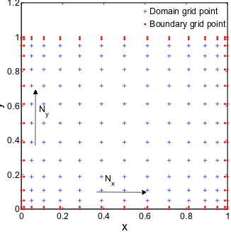
whereP; Q; R; Swith subscriptsx; yare the DQM weighting coef-ficient matrices for the first, second, third, and fourth order partial derivatives with respect tox and y directions, respectively. The unknown functionf is expressed in matrix form along the two-dimensional grid, as shown inFig. 1and superscriptTrepresents the transpose of the matrix. The domain grid points refer to the points where the governing partial differential equations are expressed in DQM form and the boundary grid points refer to the points where multiple boundary conditions are applied (Fig. 1). The information regarding the grid distribution for computation
of weighting coefficient matrices and modelling multiple boundary conditions are explained, in detail, in the textbook byShu (2000).
3. Postbuckling analysis of VAT panels
In symmetric VAT panels, stiffness (A;Dmatrices) varies with
x—y coordinates and the constitutive equation in partial inverse form is given by,
0 M( ) ¼ A
ðx;yÞ 0 0 Dðx;yÞ
N
j
( )
; ð3Þ
whereN; Mare the stress and moment resultants,A¼A1is the compliance matrix andDis the bending stiffness matrix. The non-linear midplane strains
0and curvaturesj
are defined as 0x¼u;xþ
1 2w
2
;xþw;xw0;x;
0y¼v
;yþ1 2w
2
;yþw;yw0;y;
0xy¼u;yþ
v
;xþw;xw;yþw;xw0;yþw;yw0;x;j
x¼ w;xx;j
y¼ w;yy;j
xy¼ 2w;xyð4Þ
whereu;
v
; ware the displacements andw0is the initial imperfec-tion funcimperfec-tion. A stress funcimperfec-tionXis introduced such that the stress resultants are defined by,Nx¼
X;
yy; Ny¼X;
xx; Nxy¼X;
xy: ð5ÞThe compatibility condition in terms of mid-plane strains in a plane stress condition is given by (Whitney, 1987)
0x;yyþ
0
y;xx
0
xy;xy¼w
2
;xyw;xxw;yyþ2w;xyw0;xyw;xxw0;xx
w;yyw0;xx: ð6Þ
After substitution of Eqs.(3)–(5)into Eq.(6), the final form is given by
A
11ðx;yÞ
X;
yyyy2A16ðx;yÞX;
xyyyþ ð2A12ðx;yÞ þA
66ðx;yÞÞ
X;
xxyy2A26ðx;yÞ
X;
xxxyþA22ðx;yÞX;
xxxxþ ð2A11;yðx;yÞA
16;xðx;yÞÞ
X;
yyyþ ð2A12;xðx;yÞ 3A
16;yðx;yÞ
þA
66;xðx;yÞÞ
X;
xyyþ ð2A12;yðx;yÞ 3A
26;xðx;yÞ
þA66;yðx;yÞÞ
X;
xxyþ ð2A22;xðx;yÞ A
26;yðx;yÞÞ
X;
xxxþ ðA11;yyðx;yÞ þA
12;xxðx;yÞ A
16;xyðx;yÞÞ
X;
yyþ ðA26;xxðx;yÞA
16;yyðx;yÞ þA
66;xyðx;yÞÞ
X;
xyþ ðA12;yyðx;yÞ þA
22;xxðx;yÞ
A26;xyðx;yÞÞ
X;
xx¼w2
;xyw;xxw;yyþ2w;xyw0;xyw;xxw0;xxw;yyw0;xx: ð7Þ
0 0.2 0.4 0.6 0.8 1 0 0.2 0.4 0.6 0.8 1 1.2 x y N x
Domain grid point Boundary grid point
N
[image:2.595.357.520.69.234.2]y
The differential equation of transverse motion that governs the postbuckling analysis of a symmetrical VAT plate is given by, @2Mx
@x2 þ2 @2Mxy
@x@yþ
@2My
@y2 þNx @2w
@x2þ @2w0
@x2
!
þ2Nxy
@2w
@x@yþ
@2w0 @x@y
! þNy
@2w @y2þ
@2w0 @y2
!
þq¼0; ð8Þ
where Mx; My; Mxy are the moment distributions and q is the
load applied inz direction (Whitney, 1987). Eqs. (3)–(5)are then substituted into Eq. (8)and the resulting differential equation is given by
D11ðx;yÞw;xxxxþ4D16ðx;yÞw;xxxyþ2ðD12ðx;yÞ þ2D66ðx;yÞÞw;xxyy
þ4D26ðx;yÞw;yyyxþD22ðx;yÞw;yyyyþ2ðD11;xðx;yÞ
þD16;yðx;yÞÞw;xxxþ ð6D16;xðx;yÞ þ2D12;yðx;yÞ þ4D66;yðx;yÞÞw;xxy
þ ð2D12;xðx;yÞ þ4D66;xðx;yÞ þ6D26;yðx;yÞÞw;xyyþ2ðD26;xðx;yÞ
þD22;yðx;yÞÞw;yyyþ ðD11;xxðx;yÞ þ2D16;xyðx;yÞ þD12;yyðx;yÞÞw;xx
þ ð2D16;xxðx;yÞ þ4D66;xyðx;yÞ þ2D26;yyðx;yÞÞw;xyþ ðD12;xxðx;yÞ
þ2D26;xyðx;yÞ þD22;yyðx;yÞÞw;yy
X
yyðw;xxþw0;xxÞþ2
X
xyðw;xyþw0;xyÞX
xxðw;yyþw0;yyÞ þq¼0: ð9ÞThus, Eqs. (7) and (9) represent coupled fourth order nonlinear elliptic partial differential equation in terms of stress functionX
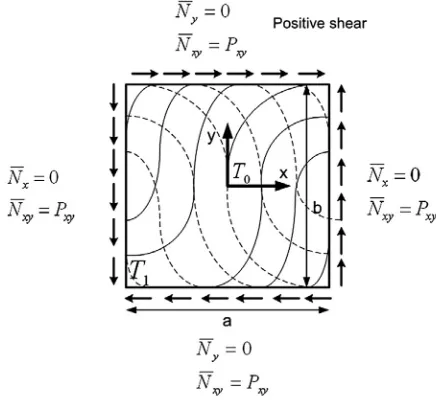
and transverse deflectionwwith variable coefficients for postbuck-ling analysis of VAT composite plates. The stress function boundary conditions are given by
X;
yyjx¼0;a¼0;X;
xxjy¼0;b¼0;X;
xyjx¼0;a;y¼0;b¼Pxy;X
jx¼0;y¼0¼X;
xjx¼0;y¼0¼X;
yjx¼0;y¼0¼0: ð10Þ where Pxy is the applied shear load. The boundary conditionsexpressed in terms ofXrepresent uniform shear applied all along the edges of the plate. The simply supported plate boundary condi-tions are given by,
x¼0;a; w¼0;
Mx¼ D11ðx;yÞw;xxD12ðx;yÞw;yy2D16ðx;yÞw;xy¼0
y¼0;b; w¼0;
My¼ D12ðx;yÞw;xxD22ðx;yÞw;yy2D26ðx;yÞw;xy¼0: ð11Þ
Chen et al. (2000)used DQM to solve the geometrically nonlinear bending problem of isotropic and orthotropic rectangular plates. Taheri and Moradi (2000) applied DQM to perform postbuckling analysis of straight fibre composites and used an arclength approach to solve the nonlinear algebraic equations. In their works, the nonlinear GDEs were written in terms of displacements (u;
v
;w) and DQM was subsequently applied to solve them. Whilst studying the nonlinear bending of orthotropic plates, the Hadamard product (), Kronecker product () and SJT product (}) of matrices were used by Chen et al. (Chen et al., 2000) to simplify the DQM form of governing differential equations. Consider matricesA; Bof sizemn, the Hadamard productABis a matrix of the same dimen-sions with elements given by
ðABÞij¼AijBij ð12Þ
Similarly, given amnmatrixAand apqmatrixB, the Kronecker productABis a matrix of sizempnqgiven by
AB¼
a11B a1nB
.. . . . . .. .
am1B amnB
2 6 6 4 3 7 7
5 ð13Þ
The SJT product (}) between a matrixAof sizemnand a vector~
v
of sizem1 results in a matrix of same size asAand is expressed asA}~
v
¼A ðI~v
Þ ð14ÞwhereIis the identity matrix.Chu (2009)applied a similar direct matrix product, equivalent to Chen’s approach, to solve nonlinear integro-differential equations. In the present work, the Kronecker, Hadamard and SJT matrix products are applied to the coupled non-linear postbuckling equations (Eqs.(7) and (9)) and the DQM form of these expressions are given by,
~A
11~J
ðIySyÞ
X
~ 2~A16~J
ðPxRyÞ~
X
þ 2~A
12þ~A66
~J
ðQxQyÞ
X
~ 2~A26~J
ðRxPyÞ~
X
þ ð~A
22~JÞ ðSxIxÞ
X
~þ 2~A11;y~A16;x
~J
ðIyRyÞ~
X
þ 2~A
12;x3~A
16;yþ~A
66;x
~J
ðPxQyÞ~
X
þ 2~A
12;y3~A26;xþ~A66;y
~J
ðQxPyÞ~
X
þ 2~A
22;x~A26;y
~J
ðRxIxÞ
X
~þ ~A
11;yyþ~A
12;xx~A
16;xy
~J
ðIyQyÞ~
X
þ ~A
26;xx~A16;yyþ~A66;xy
~J
ðPxPyÞ~
X
þ ~A
12;yyþ~A22;xx~A26;xy
~J
ðQxIxÞ~
X
¼ ððPxPyÞw~Þ ððPxPyÞ~wÞ ððQxIxÞ~wÞ ððIyQyÞ~wÞ
þ2ððPxPyÞw~Þ ððPxPyÞw~0Þ ððQxIxÞ~wÞ ððIyQyÞw~0Þ
ððIyQyÞ~wÞ ððQxIxÞw~0Þ; ð15Þ
ð~D11~JÞ ðSxIxÞ~wþ ð4~D16~JÞ ðRxPyÞw~
þ ð2ð~D12þ2D~66Þ JÞ ðQxQyÞw~þ ð4~D26~JÞ ðRxPyÞ~w
þ ð~D22~JÞ ðIySyÞ~wþ ð2ðD~11;xþ~D16;yÞ ~JÞ ðRxIxÞw~
þ ðð6~D
16;xþ2~D12;yþ4~D66;yÞ ~JÞ ðQxPyÞw~
þ ðð2~D
12;xþ4~D66;xþ6~D26;yÞ ~JÞ ðPxQyÞw~
þ ð2ð~D26;xþ~D22;yÞ ~JÞ ðIyRyÞ~w
þ ðð~D11;xxþ2~D16;xyþ~D12;yyÞ ~JÞ ðQxIxÞ~w
þ ðð2~D
16;xxþ4~D66;xyþ2~D26;yyÞ ~JÞ ðPxQyÞw~
þ ðð~D12;xxþ2~D26;xyþ~D22;yyÞ ~JÞ ðIyQyÞw~
ðIyByÞ
X
~ðQxIxÞð~wþ~w0Þ þ2ðPxPyÞX
~ðPxPyÞð~wþ~w0ÞðQxIxÞ
X
~ðIyQyÞðw~þw~0Þ þ~q¼0; ð16Þ where~X; ~w; ~w0; ~q; ~Aij; ~Dijði;j¼1;2;6Þare vectors generated bystacking the columns of the corresponding matrices X;w;w0;q;
A
ij;Dij; ~J¼ ½1;1;. . .;11N is a row vector, N¼NxþNy represents
the total number of grid points in the two-dimensional domain andNx; Nyrepresent the number of grid points along thexandy
directions. The size of the identity matricesIx; Iy depends on Nx
andNy, respectively. Eqs.(15) and (16)are further simplified into
matrix forms given by
L1~
X
¼ ðL2w~Þ ðL2w~Þ ðL3~wÞ ðL4~wÞ þ2ðL2w~Þ ðL2w~0ÞðL3~wÞ ðL4w~0Þ ðL4w~Þ ðL3w~0Þ;
L5w~ ðL6~
X
Þ ðL3ð~wþw~0ÞÞ þ2ðL7~X
Þ ðL2ðw~þw~0ÞÞThe matrix operators in Eq.(17)are given by, L1¼ ð~A11~JÞ ðIySyÞ ð2~A16~JÞ ðPxRyÞ
þ ðð2~A
12þ~A66Þ ~JÞ ðQxQyÞ ð2~A26~JÞ ðRxPyÞ
þ ð~A
22~JÞ ðSxIxÞ þ ðð2~A11;y~A16;xÞ ~JÞ ðIyRyÞ
þ ðð2~A
12;x3~A16;yþ~A66;xÞ ~JÞ ðPxQyÞ
þ ðð2~A
12;y3~A
26;xþ~A
66;yÞ ~JÞ ðQxPyÞ
þ ðð2~A
22;x~A26;yÞ ~JÞ ðRxIxÞ
þ ðð~A
11;yyþ~A12;xx~A16; xyÞ ~JÞ ðIyQyÞ
þ ðð~A
26;xx~A16;yyþ~A66; xyÞ ~JÞ ðPxPyÞ
þ ðð~A
12;yyþ~A22;xx~A26; xyÞ ~JÞ ðQxIxÞ;
L2¼PxPy; L3¼QxIx; L4¼IyQy;
L5¼ ð~D11~JÞ ðSxIxÞ þ ð4~D16~JÞ ðRxPyÞ
þ ð2ð~D12þ2~D66Þ JÞ ðQxQyÞ þ ð4~D26~JÞ ðRxPyÞ
þ ð~D22~JÞ ðIySyÞ þ ð2ðD~11;xþ~D16;yÞ ~JÞ ðRxIxÞ
þ ðð6~D16;xþ2~D12;yþ4~D66;yÞ ~JÞ ðQ
xPyÞ
þ ðð2~D12;xþ4~D66;xþ6~D26;yÞ ~JÞ ðPxQyÞ
þ ð2ð~D26;xþ~D22;yÞ ~JÞ ðIyRyÞ
þ ðð~D11;xxþ2~D16;xyþD~12;yyÞ ~JÞ ðQxIxÞ
þ ðð2~D
16;xxþ4~D66;xyþ2~D26;yyÞ ~JÞ ðPxPyÞ
þ ðð~D12;xxþ2~D26;xyþD~22;yyÞ ~JÞ ðIyQyÞ;
L6¼IyQy; L7¼PxPy; L8¼QxIx; ð18Þ
where is the Kronecker matrix product and is the Hadamard matrix product and all the matrix operators are of sizeNN. Various methods have been reported previously for implementation of multi-ple boundary conditions along the plate edges using DQM (Shu, 2000). In the current work, the direct substitution method proposed byShu and Du (1997, 1999)has been used to implement the different combination of plate boundary conditions. Using this approach, the boundary conditions for stress function and transverse displacement were applied to the boundary grid points in the DQM domain. The values at the boundary grid points were expressed in terms of unknown domain grid point values. The modified matrices are reduced to size NdNd where Nd represent the total number of
domain points and the modified DQM equations are given by, ~
X
dðw~dÞ ¼L11ððL2~wdÞ ðL2w~dÞ ðL3~wdÞ ðL4~wdÞ þ2ðL2~wdÞ ðL2~w0dÞðL3~wdÞ ðL4w~0dÞ ðL4w~dÞ ðL3w~0dÞÞ;
U
ðw~dÞ ¼L5w~d ðL6~X
dÞ ðL3ð~wdþw~0dÞÞ þ2ðL7
X
~dÞ ðL2ð~wdþw~0dÞÞðL8~
X
dÞ ðL4ðw~dþ~w0dÞÞ þ~qd¼0; ð19Þwhich represent the nonlinear algebraic DQM equations as a func-tion of transverse displacement (~wd) and were solved using a
New-ton–Raphson algorithm. The Jacobian of these equations with respect tow~dis obtained using the SJT matrix product as,
@ ~
X
dðw~dÞ@ ~wd
¼L1
1 ð2L2}ðL2w~dÞ ðL3}L3w~dþL4}L3w~dÞ
þ2ðL2}L2w~0dÞ ðL3}L4w~0dÞ
ðL4}L3~w0dÞÞ;
@
U
ð~wdÞ @ ~wd¼L5 L6 @~
X
d@ ~wd
}L3ð~wdþw~0dÞ þL3}L6~
X
d!
þ2 L7 @~
X
d@ ~wd
}L2ðw~dþ~w0dÞ þL2}L7
X
~d!
L8 @~
X
d@ ~wd
}L4ðw~dþ~w0dÞ þL4}L8~
X
d!
: ð20Þ
The SJT product allows computation of the Jacobian for discretized nonlinear partial differential equations similar to calculation of derivative of a single variable scalar function. The SJT approach facilitates fast and accurate evaluation of the Jacobian matrix and the Newton–Raphson iteration approach is used to determine the nonlinear displacement field
~ wðdiþ1Þ¼w~
ðiÞ
d
@
U
ðw~ðdiÞÞ@ ~wd
!1
U
ðw~ðdiÞÞ; ð21ÞThe Newton–Raphson algorithm ensures quadratic convergence and requires few iterations to converge for each load step applied in the nonlinear postbuckling regime.
4. Problem definition
The VAT plates considered are symmetrically laminated and the material properties for each lamina are given by E1= 181 GPa,
E2= 10.27 GPa, G12= 7.17 GPa,
m
12= 0.28 with lamina thicknesst= 1.272 mm and number of laminae,n= 8. The VAT plate with lin-ear angle variation along thexdirection is given by
hðxÞ ¼/þ2ðT1T0Þ
a jxj þT0; ð22Þ
where/is the angle of rotation,T0is the fibre orientation angle at the panel centerx¼0, andT1is the fiber orientation angle at the panel endsx¼ a=2 (seeFig. 2). The non-uniform grid distribution given by the Chebyshev–Gauss–Labotto points are used for the computation of weighting matrices and is given by
Xi¼
1 2 1cos
i1
N1
p
; i¼1;2;. . .N; ð23Þ
[image:4.595.326.544.540.740.2]whereNis the number of grid points. In order to validate the DQM results, finite element modelling of the VAT panels was carried out using ABAQUS. The S4 shell element was chosen for discretization of the VAT plate structure. To achieve good accuracy, mesh sizes of 4040; 9030 were selected for plates with aspect ratio 1 and 3, respectively. Using the linear fibre angle definition, fibre ori-entation was evaluated at the centroid of each element. The mate-rial properties for elements were then defined using the fibre orientation information. Prior to the buckling analysis, in-plane analysis of the VAT laminates under shear was carried out to com-pute the stress resultant distributions. The in-plane analysis results
were then used in the buckling analysis for evaluating the critical shear buckling load efficient. The postbuckling of VAT plates was then performed using buckling analysis results. The imperfection function required for nonlinear FE analysis was chosen to be the first buckling mode shape. The imperfection magnitude was taken to be one percent of the plate thickness and the arc length param-eters required for Riks analysis were adapted to the particular VAT configuration that was studied. All plates considered in this study were considered to be simply supported.
Buckling results are normalised with respect to that of a homo-geneous quasi-isotropic (QI) laminate. The laminates
½45=45=0=90s; ½90=0=45=45s are commonly termed QI, yet
they contain different amounts of flexural anisotropy (Diaconu and Weaver, 2006). To nullify the effects of flexural anisotropy we have chosen a layup of 48 layers comprising 0; 90; 45 fibre orientations. Alternatively, the homogeneous QI laminate with equivalent Young’s modulusEiso, Poisson’s ratio
m
isoand bendingstiffnessDisoare given by (Pandey and Sherbourne, 1993; Weaver
and Nemeth, 2007),
Diso¼
Eisoh
3
12ð1
m
2isoÞ
;
m
iso¼U4 U1
; Eiso¼U1ð1
m
2isoÞ; ð24ÞwhereU1; U2; U4are material invariants (Jones, 1998). The critical buckling loadNxycris normalised with respect to the critical
buck-ling state Niso
xycr of a homogeneous QI laminate. In the numerical
study, the effects of in-plane extension-shear couplingA16; A26 on the shear buckling and postbuckling performance of VAT composite plates are investigated.
5. Results and discussion
5.1. Buckling analysis under in-plane shear load
The buckling problem of VAT plates was solved by neglecting the nonlinear terms in Eq.(9)and DQM was then applied to solve the resulting governing differential equations. Initially, the effect of direction of shear load on the buckling behaviour of unidirectional composite plates with different fibre angle orientations and aspect ratios was studied. The DQM simulation was carried out using
Nx¼Ny¼19 grid points for square plate (a=b=0.254 m,
thick-ness = 1 mm) andNx¼Ny¼21 grid points for a rectangular plate
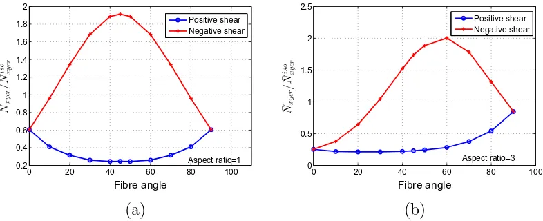
with aspect ratio = 3 (a= 0.762 m,b= 0.254 m, thickness = 1 mm). The normalised buckling load obtained using DQM is shown in Fig. 3. The buckling loads obtained under negative shear are higher than positive shear and this behaviour can be attributed to the
alignment of compressive force in the fibre direction by the applied negative shear load. For square and rectangular plates, the 45°and 60°layup respectively, show higher shear buckling performance compared to all other fibre orientations.
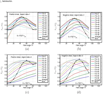
Next, the buckling performance of VAT plates under shear load was studied for different linearly varying fibre angle distributions. The DQM grid size was chosen to beNx¼Ny¼19 for a square
plate (a=b=0.254 m, thickness = 1 mm) and Nx¼Ny¼21 for a
plate with aspect ratio = 3 (a= 0.762 m, b= 0.254 m, thick-ness = 1 mm) based on convergence studies. The normalised shear buckling load evaluated using DQM is shown in Fig. 4for VAT plates with/¼0 and various values ofT0; T1. In the case of square plates, the straight fibre layup½45;452s shows higher buckling
load for both positive and negative shear when compared to all other VAT layups. For composite plates with aspect ratio = 3, the straight fibre layup½60;602sexhibits high buckling load for both
positive and negative shear.Fig. 5shows the buckling load results for VAT plates with /¼45 and different values of T0; T1. For square plates under negative shear, the straight fibre layup½458 shows higher buckling coefficient of 1.91 compared to all VAT plates. This is mainly because the laminate½458 is unbalanced and the finite extensional-shear coupling stiffness coefficients
A16; A26introduceNx; Ny distributions which enhances the
nega-tive shear buckling performance. However, for rectangular plates, the VAT layups (45 h45j0i2s;45 h50j0i2s) shows high buckling
load compared to all other layups. The improvement in buckling performance of VAT plates under constant shear load is not as sig-nificant as observed under axial compression (Raju et al., 2012).
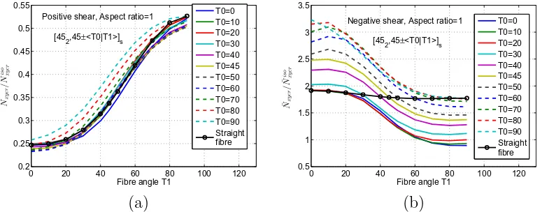
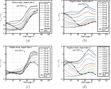
Furthermore, we studied the effect of A16; A26 coefficients on the shear buckling performance by choosing symmetric unbal-anced laminates containing both straight fibre and VAT layups. For the numerical study, the square plate with layup configuration
½452;45 hT0jT1is was considered and the normalised buckling
load results are shown inFig. 6. The buckling results for negative shear clearly shows that many layups attain higher values than straight fibre designs, whereas the results under positive shear are not as high compared to negative shear. The reason is due to the compressive component of the applied negative shear load act-ing along the 45°straight fibre direction. In addition, the added 45 layers to the VAT layups make the laminate unbalanced and intro-duces non-zero extensional-shear coupling stiffness coefficient
A16; A26 distributions. TheseA16; A26 distributions result in sec-ondary stress resultant states in the plate which aids the buckling resistance in the negative shear direction. If the straight fibre and VAT layups are rotated by 90°, the buckling performance under positive shear will be higher than straight fibre layups, but result
0 20 40 60 80 100 0.2
0.4 0.6 0.8 1 1.2 1.4 1.6 1.8 2
Fibre angle
Positive shear Negative shear
Aspect ratio=1
0 20 40 60 80 100 0
0.5 1 1.5 2 2.5
Fibre angle
Positive shear Negative shear
Aspect ratio=3
[image:5.595.96.489.580.740.2](a)
(b)
in the reduction of buckling performance under negative shear. The composite layup ½452;45 h90j0is exhibits a high normalised
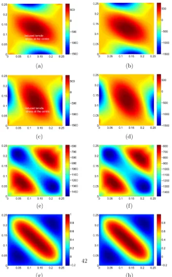
buckling coefficient equal to 3.23 compared to all other layups, under negative shear. The in-plane stress resultant distributions and buckling mode shape computed using DQM and FE modelling for the ½452;45 h90j0is layup are shown in Fig. 7. The DQM
results correlate well with FE and requires fewer grid points (1919) than FE mesh density (4040). The stress resultant dis-tributionsNx; Nyfor the layup½452;45 h90j0isshow nonuniform
tensile stress in the middle of the plate due to the chosen fibre path and these secondary tensile forces offer additional resistance to buckling under negative shear. TheNxy distribution for the layup
½452;45 h90j0isshows little redistribution of the shear load from
the centre of the plate to the edges. However, if the unbalanced layup effects due to addition of 45°layups is eliminated by making theA16; A26distributions equal to zero, the computed normalised shear buckling coefficient is 2.61 and reduction of 19.2% in the buckling coefficient is observed. Thus, the 45°straight fibre layups in the½452;45 h90j0islaminate resists the primary compressive
load and when combined with the VAT layups are responsible for the induced secondary tensile stress state in the laminate. Both straight and VAT fibre layups complement each other for the improvement of shear buckling performance. Thus, under shear load boundary conditions the improvement in buckling perfor-mance is not entirely due to tow steering and this is mainly due to the effect ofA16; A26distributions as a result of making the lam-inate unbalanced. The lamlam-inate can also be made unbalanced by choosing VAT layups instead of the 45° which can considerably improve the shear buckling performance compared with
½452;45 hT0jT1islaminates.
The shear buckling performance of rectangular composite lay-ups½602;60 hT0jT1is (aspect ratio = 3) are shown inFig. 8. The
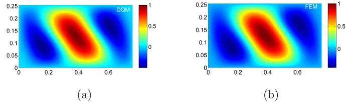
layup½602;60 h90j10isunder negative shear has higher buckling
load compared to other composite layups. The buckling mode shape of the layup½602;60 h90j10is was evaluated using DQM
and FE modelling and the results are shown inFig. 9. Furthermore, theA16; A26stiffness coefficient distributions of the VAT plates play a critical part in the improvement of shear buckling performance. The computation of shear buckling load will be erroneous, if the effects of in-plane extension-shear coupling coefficientsA16; A26 are ignored and results in a lower buckling load. Thus, we conclude from this numerical study, the improvement in buckling perfor-mance under shear load can be achieved by tailoring theA16; A26 distributions by designing symmetric unbalanced hybridised straight fibre-VAT laminates.
5.2. Buckling analysis under in-plane shear displacement
In this section, the buckling behaviour of VAT plates under shear displacement is investigated. The edges of the plate are kept straight during the application of shear displacement and the sche-matics of the VAT plate shown inFig. 10explains the applied dis-placement boundary conditions. The in-plane disdis-placement boundary conditions are given by
x¼ a
2; u¼
D
x;v
¼D
y; y¼ b2; u¼ 2
D
xax;
v
¼2D
ya x;
ð25Þ
0 20 40 60 80 100 120 0.4
0.5 0.6 0.7 0.8 0.9 1
Fibre angle T1
T0=0 T0=10 T0=20 T0=30 T0=40 T0=45 T0=50 T0=60 T0=70 T0=80 T0=90 Straight fibre Positive shear, Aspect ratio=1
0±<T0|T1>
2s
0 20 40 60 80 100 120 0.4
0.6 0.8 1 1.2 1.4 1.6 1.8
Fibre angle T1
T0=0 T0=10 T0=20 T0=30 T0=40 T0=45 T0=50 T0=60 T0=70 T0=80 T0=90 Straight fibre 0±<T0|T1>
2s
Negative shear, Aspect ratio=1
(a)
(b)
0 20 40 60 80 100 120 0.2
0.3 0.4 0.5 0.6 0.7 0.8 0.9 1 1.1
Fibre angle T1
T0=0 T0=10 T0=20 T0=30 T0=40 T0=45 T0=50 T0=60 T0=70 T0=80 T0=90 Straight fibre 0±<T0|T1>
2s
Positive shear, Aspect ratio=3
0 20 40 60 80 100 120 0.2
0.4 0.6 0.8 1 1.2 1.4 1.6 1.8
Fibre angle T1
T0=0 T0=10 T0=20 T0=30 T0=40 T0=45 T0=50 T0=60 T0=70 T0=80 T0=90 Straight fibre 0±<T0|T1>
2s
Negative shear, Aspect ratio=3
[image:6.595.105.501.370.730.2](c)
(d)
where
a
¼sin1 2Dxa
; Dy¼a2ð1cos
a
Þand Dx is the applieddis-placement magnitude. As the boundary conditions are specified solely in terms of displacements, DQM was applied to solve the in-plane coupled partial differential equations expressed in terms of displacements instead of the stress function based differential equation. Details of the GDEs expressed in terms of displacement
u;
v
; w for solving the prebuckling, buckling and postbuckling problem of symmetric VAT plates are given in the Appendix. This approach was taken due to the difficulty in applying the displace-ment based conditions in terms of stress function, as they are expressed using integral expressions which are nonlocal boundaryconditions and pose additional problems to satisfy them accurately at the boundary grid points. The DQM procedure discussed in the work ofGroh and Weaver (2014)was used here to solve the pre-buckling problem expressed in terms of in-plane displacements. The resulting DQM algebraic equations were solved for shear dis-placement boundary conditions and results in non-uniform stress resultant distributions for VAT plates. To determine the average shear buckling load applied to the VAT panel, it is essential to exam-ine the contribution of each stress resultant in satisfying the speci-fied displacement boundary conditions. For the edges to be straight, the stress resultantsNx; Nyare nonzero along the edges and have 0 20 40 60 80 100 120
0.2 0.4 0.6 0.8 1 1.2 1.4 1.6 1.8 2
Fibre angle T1
T0=0 T0=10 T0=20 T0=30 T0=40 T0=45 T0=50 T0=60 T0=70 T0=80 T0=90 Straight fibre Positive shear, Aspect ratio=1
45±<T0|T1>
2s
0 20 40 60 80 100 120 0.2 0.4 0.6 0.8 1 1.2 1.4 1.6 1.8 2
Fibre angle T1
T0=0 T0=10 T0=20 T0=30 T0=40 T0=45 T0=50 T0=60 T0=70 T0=80 T0=90 Straight fibre Negative shear, Aspect ratio=1
45±<T0|T1>
2s
(a)
(b)
0 20 40 60 80 100 120 0.2 0.4 0.6 0.8 1 1.2 1.4 1.6 1.8 2
Fibre angle T1
T0=0 T0=10 T0=20 T0=30 T0=40 T0=45 T0=50 T0=60 T0=70 T0=80 T0=90 Straight fibre Positive shear, Aspect ratio=3
45±<T0|T1>2s
0 20 40 60 80 100 120 0.2 0.4 0.6 0.8 1 1.2 1.4 1.6 1.8 2
Fibre angle T1
T0=0 T0=10 T0=20 T0=30 T0=40 T0=45 T0=50 T0=60 T0=70 T0=80 T0=90 Straight fibre 45±<T0|T1>
2s
Negative shear, Aspect ratio=3
[image:7.595.97.491.71.381.2](c)
(d)
Fig. 5.Square VAT plate 45 hT0jT1i2ssubjected to in-plane shear load (a) positive shear, aspect ratio = 1 (b) negative shear, aspect ratio = 1 (c) positive shear, aspect ratio = 3 (d) negative shear, aspect ratio = 3.
0 20 40 60 80 100 120 0.2 0.25 0.3 0.35 0.4 0.45 0.5 0.55
Fibre angle T1
T0=0 T0=10 T0=20 T0=30 T0=40 T0=45 T0=50 T0=60 T0=70 T0=80 T0=90 Straight fibre Positive shear, Aspect ratio=1
[45
2,45±<T0|T1>]s
0 20 40 60 80 100 120 0.5 1 1.5 2 2.5 3 3.5
Fibre angle T1
T0=0 T0=10 T0=20 T0=30 T0=40 T0=45 T0=50 T0=60 T0=70 T0=80 T0=90 Straight fibre Negative shear, Aspect ratio=1
[45
2,45±<T0|T1>]s
(a)
(b)
[image:7.595.101.487.436.588.2]considerable magnitude which cannot be ignored when com-pared to Nxy (Fig. 11). The non-zero stress resultants along the
edges of the VAT plate result in moment distributions which have to be considered in evaluating the applied shear load. Detailed procedures for the computation of the moment due to
stress resultants are explained in the work of Waldhart (1996). The moments due to Nx; Nxy along edge x¼a=2 and moments
due to Ny; Nxy along edge y¼b=2 were used to compute the
average applied shear resultant Nave
[image:8.595.127.481.63.633.2]xy. The moments due to Nx; Ny; Nxy are defined as,
Mi z¼
Zb=2
b=2
yNxða=2;yÞdy;
Miiz¼
Z a=2
a=2
xNyðx;b=2Þdx;
Miii z ¼ b=2
Z a=2
a=2
Nxyðx;b=2Þdx;
Mizv¼a=2
Z b=2
b=2
Nxyða=2;yÞdy
ð26Þ
whereMi
zis the moment about thezaxis by theNxacting along the
edgex¼a=2; Mii
z is the moment about thezaxis by theNyacting
along the edgey¼b=2, andMiiiz; M iv
z are the moments about thez
axis created byNxyacting along the edgesx¼a=2; y¼b=2,
respec-tively. In this work, the moment in the anticlockwise direction is taken to be positive. Under positive shear deformation,Miii
z is
nega-tive andMizvis positive, but the sign ofM i
z; M
ii
zdepends on the fibre
path distribution and cannot be predetermined. Therefore, the posi-tive and negaposi-tive moments are given by,
Mþ
¼Miv
z þ
Mi z; M
i zP0
0; Mi z<0
! þ M
ii z; M
ii zP0
0; Mii z<0
!
;
M
¼Miii z þ
0; MizP0
Miz; M i z<0
!
þ 0; M
ii zP0
Miiz; M ii z<0
!
:
ð27Þ
0 20 40 60 80 100 120 0.25
0.3 0.35 0.4 0.45 0.5 0.55 0.6 0.65 0.7
Fibre angle T1
T0=0 T0=10 T0=20 T0=30 T0=40 T0=45 T0=50 T0=60 T0=70 T0=80 T0=90 Straight fibre Positive shear, Aspect ratio=3
[60
2,60±<T0|T1>]s
0 20 40 60 80 100 120 1.4
1.6 1.8 2 2.2 2.4 2.6 2.8
Fibre angle T1
T0=0 T0=10 T0=20 T0=30 T0=40 T0=45 T0=50 T0=60 T0=70 T0=80 T0=90 Straight fibre Negative shear, Aspect ratio=3
[60
2,60±<T0|T1>]s
[image:9.595.101.487.68.223.2](a)
(b)
[image:9.595.117.462.260.362.2]Fig. 8.Rectangular VAT plate½602;60 hT0jT1issubjected to in-plane shear load (a) positive shear, aspect ratio = 1 (b) negative shear, aspect ratio = 3.
Fig. 9.Rectangular VAT plate½602;60 h90j10issubjected to in-plane negative shear load: Buckling mode shape (a) DQM (b) FEM.
Fig. 10.Square VAT plate subjected to positive in-plane shear displacement.
Fig. 11.VAT plate subjected to positive in-plane shear displacement: variation of
[image:9.595.335.511.399.565.2] [image:9.595.74.245.404.618.2]The average of the moments Mþ; M was used to compute the average shear load given by,
Nave xy ¼
1 ab jM
þj þ jMj
: ð28Þ
The stress resultants obtained from the in-plane analysis of VAT plates were then used for computing the critical shear buckling load given byNxycr¼kcrNaxyvewherekcris the minimum eigenvalue. The
buckling performance of VAT plates under shear displacement was studied for different aspect ratios. The DQM grid size was cho-sen to beNx¼Ny¼21 for the square plate andNx¼Ny¼25 for
plate with aspect ratio = 3 based on convergence studies. For VAT plates with/¼0 and various values ofT0; T1, the normalised posi-tive and negaposi-tive shear buckling loads evaluated using DQM are shown in Fig. 12. For square VAT plates, the layup 0 h0j45i2s
shows high positive and negative shear buckling load when com-pared to all other layups. For rectangular VAT plates, the layup 0 h90j45i2sshows better buckling performance than other layups. The VAT laminates considered until now are balanced and there is no effect of A16; A26 stiffness coefficients on the shear buckling performance.
Next, we investigate the effects ofA16; A26stiffness coefficients on the shear buckling performance of VAT laminates 45hT0jT1i2s; 45 hT0jT1i2s for different aspect ratios. Both the
VAT layups 45hT0jT1i2s; 45 hT0jT1i2s have different fibre angle
definitions based on the location of the ±sign with respect to the rotation angle/(Waldhart, 1996). In the VAT layup 45hT0jT1i2s,
a ±sign in front of the/means the reference fibre paths are rotated in equal and opposite amounts. For VAT layups 45hT0jT1i2s, the
fibre angle definition results in a balanced laminate in certain regions and unbalanced laminate elsewhere. This introduces finite
A16; A26distributions in the VAT laminates. The normalised buck-ling load for VAT layups 45hT0jT1i2s was computed using DQM
and is shown inFig. 13and the values are high compared to the straight fibre and VAT layups 0 hT0jT1i2s. This is primarily due
to the redistribution of applied shear loads from the centre of the panel towards the edge and also the nonzeroA16; A26stiffness dis-tributions play a small role in improvement in buckling perfor-mance in either positive or negative shear direction.
For VAT layups 45 hT0jT1i2s, the fibre angle definition results
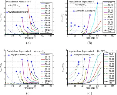
in symmetric and unbalanced laminate configurations. These VAT laminates exhibit higher magnitude ofA16; A26stiffness distribu-tions because of their unbalanced layup sequence at each point. The shear buckling results of the VAT layups 45 hT0jT1i2s are
shown inFig. 14and exhibit some interesting behaviour. The term asymptotic buckling limit has been introduced to explain the buck-ling results shown inFig. 14. An asymptotic buckling limit repre-sents the VAT layup configuration 45 hT0jT1i2s beyond which
the VAT layups have effectively infinite shear buckling resistance (i.e. they do not buckle) in the negative or positive direction. In the case of VAT layup 45 h20jT1i2s, an asymptotic buckling load
limit of 6.65 is attained atT1¼60and exhibits effectively infinite shear buckling resistance forT0¼20andT1>60in the positive shear direction. Similarly, VAT layup 45 h30jT1i2shas an
asymp-totic buckling load limit of 16.15 atT1¼80and infinite negative shear buckling resistance forT0¼30andT1>80. Another inter-esting observation is the large difference in the normalised buck-ling coefficient value, for example, between layups of similar configuration 45 h45j45i2sand 45 h40j45i2s. This is due to the
effect of A16; A26 distributions in the VAT laminates. The 45 h45j45i2s layup is equivalent to a cross-ply layup with
stiff-ness coefficients A16; A26. For VAT layup 45 h40j45i2s, the
0 20 40 60 80 100 120 0.4
0.6 0.8 1 1.2 1.4
Fibre angle T1
T0=0 T0=10 T0=20 T0=30 T0=40 T0=45 T0=50 T0=60 T0=70 T0=80 T0=90 Straight fibre 0±<T0|T1>
2s
Positive shear, Aspect ratio=1
0 20 40 60 80 100 120 0.8
1 1.2 1.4 1.6 1.8 2
Fibre angle T1
T0=0 T0=10 T0=20 T0=30 T0=40 T0=45 T0=50 T0=60 T0=70 T0=80 T0=90 Straight fibre 0±<T0|T1>
2s
Negative shear, Aspect ratio=1
(a)
(b)
0 20 40 60 80 100 120 0.2
0.4 0.6 0.8 1 1.2 1.4 1.6 1.8
Fibre angle T1
T0=0 T0=10 T0=20 T0=30 T0=40 T0=45 T0=50 T0=60 T0=70 T0=80 T0=90 Straight fibre Positive shear, Aspect ratio=3
0±<T0|T1>
2s
0 20 40 60 80 100 120 0
0.5 1 1.5 2 2.5
Fibre angle T1
T0=0 T0=10 T0=20 T0=30 T0=40 T0=45 T0=50 T0=60 T0=70 T0=80 T0=90 Straight fibre Negative shear, Aspect ratio=3
0±<T0|T1>
2s
[image:10.595.110.499.413.732.2](c)
(d)
laminates are unbalanced resulting in finiteA16;A26 distributions and they introduceNx; Ny; Nxydistributions in the VAT laminate
to keep the edges of the plate straight. These non-uniform pre-buckling stress resultants are responsible for the improvement in shear buckling load coefficient and for the difference in buckling results for similar VAT layup configurations.
The VAT layup 45 h30j80i2s has normalised buckling load
coefficient of 16.15 under negative shear and the stress resultant distributions corresponding to this layup are shown inFig. 15such that the interior of the plate is effectively stress-free. The DQM results validate the FE modelling solutions and the stress resultant field shows the load redistribution towards the edges of the plate. The maximum and minimum principal stress resultants for the VAT layup 45 h30j80i2sare shown inFig. 16and show the
com-pressive component of the applied shear being redistributed from the centre towards the plate edges. Under positive shear, the VAT layup 45 h20j60i2s has normalised buckling load coefficient of
6.65 and the stress resultant distribution corresponding to this layup is shown inFig. 17such that a stress-free state is observed at the centre of the plate. The stress resultant distributions shown inFigs. 15 and 17indicate the load redistribution responsible for the improvement in shear buckling performance under negative and positive shear, respectively. For rectangular VAT plates, the layup 45 h30j90i2s has a high normalised buckling coefficient
value of 5.56 and the corresponding mode shape computed using DQM is shown inFig. 18. Furthermore, theA16; A26stiffness distri-butions have considerable effect on the pre-buckling stress redis-tribution of symmetric unbalanced VAT layups and are responsible for better buckling performance in either positive or negative shear direction. We conclude, from this study, that for shear buckling under displacement boundary conditions, the
redis-tribution of applied load plays a primary role in improvement of shear buckling performance.
5.3. Postbuckling analysis under in-plane shear load
The DQM methodology was extended to perform postbuckling analysis of composite plates under uniform shear load. Initially, buckling analysis of VAT plates was performed to obtain the mode shape of the critical buckling load which is subsequently used as an imperfection function for the postbuckling analysis. For square VAT plates, the number of grid points for DQM modelling was cho-sen to beNx¼Ny¼19 based on a convergence study for accurate
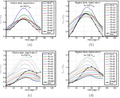
evaluation of the critical buckling load and mode shape (Raju et al., 2012). The imperfection function magnitude (1E5) for DQM was chosen to be the same as for FE modelling of the composite plate. For FE simulation, the mesh density of 4040 was selected to ana-lyse the above problem after a mesh convergence study. Subse-quently, the postbuckling behaviour of different configurations of straight fibre and VAT laminates under uniform shear was studied. The normalised shear load versus normalised maximum transverse displacement for different composite plates is shown inFig. 19and the DQM results match FE solutions relatively well. The variation of maximum transverse deflection of the VAT plate with respect to the applied shear load shows the improved postbuckling perfor-mance under negative shear rather than positive shear load. The postbuckling performance of all VAT layups under positive shear were not as good as the QI layup. The VAT layups 45 h45j30i2s; 45 h0j30i2s exhibit higher buckling load, but
lower postbuckling performance than the QI layup under negative shear. The combined straight fibre and VAT layups
½452;45 h90j0is;½452;45 h45j0is show higher buckling load 0 20 40 60 80 100 120
0.4 0.6 0.8 1 1.2 1.4 1.6 1.8 2
Fibre angle T1
T0=0 T0=10 T0=20 T0=30 T0=40 T0=45 T0=50 T0=60 T0=70 T0=80 T0=90 Straight fibre Positive shear, Aspect ratio=1
±45<T0|T1>
2s
0 20 40 60 80 100 120 0
0.5 1 1.5 2 2.5
Fibre angle T1
T0=0 T0=10 T0=20 T0=30 T0=40 T0=45 T0=50 T0=60 T0=70 T0=80 T0=90 Straight fibre Negative shear, Aspect ratio=1
±45<T0|T1>
2s
(a)
(b)
0 20 40 60 80 100 120 0.5
1 1.5 2 2.5
Fibre angle T1
T0=0 T0=10 T0=20 T0=30 T0=40 T0=45 T0=50 T0=60 T0=70 T0=80 T0=90 Straight fibre Positive shear, Aspect ratio=3
±45<T0|T1>
2s
0 20 40 60 80 100 120 0.5
1 1.5 2 2.5
Fibre angle T1
T0=0 T0=10 T0=20 T0=30 T0=40 T0=45 T0=50 T0=60 T0=70 T0=80 T0=90 Straight fibre Negative shear, Aspect ratio=3
±45<T0|T1>
2s
[image:11.595.100.489.70.381.2](c)
(d)
and improved postbuckling performance under negative shear when compared to the QI layup.
DQM was then applied to study the postbuckling behaviour of rectangular plates (aspect ratio = 3) under negative shear. The number of grid points for DQM modelling was chosen to be
Nx¼Ny¼25 based on a convergence study. For FE modelling of
rectangular VAT plates, a mesh density of 9030 was selected. The DQM and FE results for different VAT plates are shown in Fig. 20. The straight fibre layup½608and VAT layup 45 h45j0i2s
show better postbuckling performance compared to QI under negative shear. The postbuckling performance for combined straight fibre and VAT layups is investigated and the results are compared with VAT layups / hT0jT1i2s shown in Fig. 20.
The layup ½602;60 h90j10is exhibits better buckling and
postbuckling performance and this improvement is significant as observed under axial compression for VAT laminates. Similar to the previously shown buckling behaviour, by tailoring the
A16; A26 distributions using symmetric unbalanced layups (½452;45 h90j0is; ½452;45 h45j0is; ½602;60 h90j10is) has
significant effect on their postbuckling performance.
5.4. Postbuckling analysis under in-plane shear displacement
In this section, the postbuckling behaviour of VAT plates subject to shear displacement boundary conditions is investigated. The GDEs for postbuckling analysis of VAT plates were expressed in terms of displacements u;
v
; w and the DQM procedure was applied to solve them. Similar to the DQM approach applied in solving Eqs. (7) and (9), the same numerical procedures were applied to convert the GDEs given in the Appendix into DQM form. The number of grid points for DQM modelling was chosen to beNx¼Ny¼21 for square plates based on a convergence study.
The postbuckling results computed using DQM for both positive and negative shear displacement are shown inFig. 21. The VAT lay-ups exhibit better shear postbuckling performance compared to homogeneous QI and straight fibre layups. Under positive shear, the layup 45 h40j45i2s shows high postbuckling performance,
but exhibits poor postbuckling performance under negative shear. Similarly, the layup 45 h30j70i2s shows good postbuckling
per-formance in negative shear and poor perper-formance in positive shear. The layup 45h0j70i2sshows reasonably good postbuckling
performance under positive and negative shear.Fig. 22shows the results of VAT plates which have high buckling and postbuckling performance under positive or negative shear compared to all other layups. The DQM postbuckling results for rectangular VAT plates (aspect ratio = 3) under positive and negative shear displacement are shown in Fig. 23. The VAT layups 45 h40j45i2s; 45 h30j90i2s show good buckling and
postbuck-ling performance under positive and negative shear displacement respectively, but poor performance in the opposite loading direc-tion. Many VAT layups exhibit good postbuckling performance under both positive and negative shear and the results of VAT plates 0 h90j45i2s; 45 h45j90i2s show this behaviour. As
observed under buckling, the tailoring of A16; A26 distributions has a significant effect on the postbuckling performance under either positive or negative shear directions. The postbuckling results computed using DQM correlate well with FE results for square and rectangular VAT plates. The improved postbuckling results observed indicate that the benefits of tow steering is even more pronounced for shear displacement than shear load bound-ary conditions. The reason is attributed primarily to the phenome-non of load redistribution due to tow steering observed under
0 20 40 60 80 100 120 0
1 2 3 4 5 6 7 8
Fibre angle T1
T0=0 T0=10 T0=20 T0=30 T0=40 T0=45 T0=50 T0=60 T0=70 T0=80 T0=90 Straight fibre Positive shear, Aspect ratio=1
45±<T0|T1>
2s
Asymptotic Buckling limit
0 20 40 60 80 100 120 0
2 4 6 8 10 12 14 16 18
Fibre angle T1
T0=0 T0=10 T0=20 T0=30 T0=40 T0=45 T0=50 T0=60 T0=70 T0=80 T0=90 Straight fibre Negative shear, Aspect ratio=1
45±<T0|T1>
2s
Asymptotic Buckling limit
(a)
(b)
0 20 40 60 80 100 120 0
1 2 3 4 5 6
Fibre angle T1
T0=0 T0=10 T0=20 T0=30 T0=40 T0=45 T0=50 T0=60 T0=70 T0=80 T0=90 Straight fibre Asymptotic Buckling limit
Positive shear, Aspect ratio=3 45±<T0|T1>
2s
0 20 40 60 80 100 120 0
1 2 3 4 5 6
Fibre angle T1
T0=0 T0=10 T0=20 T0=30 T0=40 T0=45 T0=50 T0=60 T0=70 T0=80 T0=90 Straight fibre Asymptotic Buckling limit
Negative shear, Aspect ratio=3 45±<T0|T1>
2s
[image:12.595.112.498.72.387.2](c)
(d)
prebuckling analysis. The prebuckling stress resultant distributions redistribute the local compressive stress from the centre towards the edge of the plate and during postbuckling analysis the stress distribution does not change much with the applied shear load.
5.5. Postbuckling analysis under combined axial compression and shear
[image:13.595.114.468.66.666.2]VAT plate (0 h45j30i2s) with a load ratio ofNxy=Nx¼0:5 was
con-sidered for the numerical study. The variation of maximum trans-verse centre deflection with increasing axial compression and
[image:14.595.129.486.70.213.2] [image:14.595.128.476.251.551.2]shear is shown inFig. 25. The direction of applied shear load has considerable influence on the postbuckling behaviour. The results show that negative shear improves slightly and positive shear Fig. 16.Square VAT plate½45 h30j80i2ssubjected to in-plane negative shear displacement (a) maximum principal stress resultant (b) minimum principal stress resultant.
Fig. 17.Square VAT plate½45 h20j60i2ssubjected to in-plane positive shear displacement: (a) stress resultant distributionNx(b) stress resultant distributionNy(c) stress resultant distributionNxy(d) buckling mode shape.
[image:14.595.131.476.599.697.2]reduces the postbuckling performance of VAT plates. Next, a VAT plate (90 h0j75i2s) which exhibits better buckling performance
compared with straight fibre composites under axial compression was considered for the numerical study. The result shows that neg-ative shear reduces the postbuckling performance and that positive shear has little effect (Fig. 26). This arises because the effect of shear loads is reversed for angle of rotation /¼90. Thus, the results show the influence of direction of shear load on the post-buckling performance under axial compression.
5.6. Discussion
In this work, the DQM approach was successfully applied to model the buckling and postbuckling behaviour of VAT plates under uniform in-plane shear load and displacement boundary conditions. For the linear shear buckling problem, DQM required few grid points and less computational effort to achieve converged results than the FE method. Similarly, for nonlinear postbuckling analysis, DQM modelling uses few grid points, but needs more
iter-0 1 2 3 4 5 6 7 8
0 0.5 1 1.5 2 2.5 3 3.5
Non−dimensional Max Lateral deflection w/h
DQM FEM QI
45±<90|45> 2s
0±<45|30> 2s
[45,−45] 2s 45±<45|90>
2s
Positive shear Aspect ratio=1
0 1 2 3 4 5 6 7 8
0 0.5 1 1.5 2 2.5 3 3.5 4 4.5
Non−dimensional Max Lateral deflection w/h
45±<30|0> 2s
Negative shear [45]
8
QI
[45,−45] 2s 45±<0|30>2s
Aspect ratio=1
DQM FEM [45
2,45±<45|0>]s [45
2,45±<90|0>]s
[image:15.595.103.487.69.222.2](a)
(b)
Fig. 19.Square VAT plate subjected to in-plane shear load: normalised applied shear load (Nxy=Nisoxy) versus non-dimensional maximum lateral deflectionw=h(a) positive shear (b) negative shear.
0 0.5 1 1.5 2
0 0.5 1 1.5 2 2.5 3
[image:15.595.63.257.267.409.2]Non−dimensional Max Lateral deflection w/h
[60,−60]2s
Negative shear
Aspect ratio=3
45±<45|0>2s [60]8
QI
DQM FEM [602,60±<90|10>]s
[60
2,60±<45|0>]s
Fig. 20.Rectangular VAT plate (aspect ratio = 3) subjected to in-plane negative shear load: normalised applied shear load (Nxy=Nisoxy) versus non-dimensional maximum lateral deflectionw=h.
0 0.5 1 1.5 2 0
1 2 3 4 5 6
Non−dimensional Max Lateral deflection w/h [45,−45]
2s
45±<30|70>2s
±45<0|70>
2s
0±<0|45>
2s
45±<40|45>
2s
QI
DQM FEM Positive shear
Aspect ratio=1
0 0.5 1 1.5 2 0
1 2 3 4 5 6 7
Non−dimensional Max Lateral deflection w/h QI
[45,−45]
2s
0±<0|45>
2s
±45<0|70>
2s
45±<30|70>
2s
45±<40|45>2s
DQM FEM Negative shear Aspect ratio=1
(a)
(b)
Fig. 21.Square VAT plate subjected to shear displacement: normalised applied shear load (Nxy=Nisoxy) versus non-dimensional maximum lateral deflectionw=h(a) positive shear (b) negative shear.
0 0.2 0.4 0.6 0.8 1 1.2 0
5 10 15 20 25
Non−dimensional Max Lateral deflection w/h
Negative shear (DQM) Negative shear (FEM) Positive shear (DQM)
Positive shear (FEM) 45±<30|80>
2s
45±<20|60>
[image:15.595.332.523.268.410.2]2s
[image:15.595.103.484.579.731.2]ations to converge in each load step when compared to FE model-ing. This problem arises due to the nonsymmetric nature of the DQM stiffness matrix and also stronger reinforcement of all the boundary conditions at the boundary grid points. Although the DQM results were comparable to FE solutions, the method is not as general as FE modelling as it cannot be applied to structures with discontinuities/complicated geometry.
For shear load boundary conditions, the benefit for buckling and postbuckling response under negative shear is only observed when unbalanced VAT laminates are used such that a biaxial tensile stress (Fig. 7) is induced in the interior of the plate. Balanced VAT layups do not exhibit improved shear buckling and postbuck-ling behaviour in both directions as there is no load redistribution and secondary stress condition observed. Therefore, tailoring the finiteA16; A26distributions of the hybridised unbalanced VAT lam-inates introduce favourable tensile stress states and improve the shear buckling and postbuckling performance in either positive or negative directions. In the case of shear displacement, balanced VAT layups exhibit improved buckling and postbuckling perfor-mance in positive and negative shear directions compared with straight fibre laminates. In addition for unbalanced VAT layups, the A16; A26 stiffness distributions has considerable effect on the buckling and postbuckling performance in either the positive or negative shear direction. The phenomenon of redistribution of the applied shear load shown inFigs. 15 and 17is mainly respon-sible for the improved shear buckling and postbuckling perfor-mance of VAT plates. Thus, the phenomena of induced secondary tensile stress state at the centre of the plate and achievement of stress-free state at the centre by redistribution of applied load towards the edges of the plate are responsible for the improvement of shear buckling and postbuckling performance under shear load-control and displacement-load-control boundary conditions, respec-tively. Furthermore, the buckling and postbuckling results of VAT laminates under shear displacement boundary conditions is more significant than observed under load-control.
0 0.2 0.4 0.6 0.8 1 0
1 2 3 4 5 6
Non−dimensional Max Lateral deflection w/h DQM
FEM Aspect ratio=3 Positive shear
0±<90|45>
2s
±45<45|90>
2s
45±<40|45>
2s
QI
0 0.2 0.4 0.6 0.8 1 0
1 2 3 4 5 6
Non−dimensional Max Lateral deflection w/h
±45<45|90>
2s
DQM FEM QI
0±<90|45>
2s
45±<30|90>2s Aspect ratio=3 Negative shear
[image:16.595.112.494.69.227.2](a)
(b)
[image:16.595.59.278.272.456.2]Fig. 23.Rectangular VAT plate (aspect ratio = 3) subjected to shear displacement: normalised applied shear load (Nxy=Nisoxy) versus non-dimensional maximum lateral deflectionw=h(a) positive shear (b) negative shear.
Fig. 24.Square VAT plate subjected to combined axial compressive and positive in-plane shear load.
0 1 2 3 4 5 6 100
200 300 400 500 600 700
Applied compression load (N)
Non−dimensional Max Lateral deflection w/h Axial compression+positive shear Axial compression
Axial compression+negative shear 0±<45|30>
2s
Fig. 25.Square VAT plate 0 h45j30i2ssubjected to combined axial compression and shear load with load ratioNxy=Nx¼0:5.
0 0.5 1 1.5 2 2.5 3 3.5 0
100 200 300 400 500 600
Applied compression load (N)
Non−dimensional Max Lateral deflection w/h Axial compression+positive shear Axial compression
Axial compression+negative shear 90±<0|75>
2s
[image:16.595.73.266.501.646.2] [image:16.595.336.533.590.730.2]6. Conclusion
In this work, the buckling and postbuckling performance of symmetric VAT composite panels with linear fibre angle variation under in-plane shear is presented. The numerical results are com-puted using DQM for VAT plates with different aspect ratios and they correlate well with FE analysis. The numerical study show the effect of extension-shear coupling on the buckling and post-buckling performance of VAT composite plates under different in-plane boundary conditions. The physical understanding of the mechanics responsible for the improvement of buckling and post-buckling performance of VAT plates under shear load and displace-ment conditions is explained. Under constant shear load boundary condition, the linear fibre angle variation of VAT layups does not exhibit improved buckling and postbuckling behaviour. But, VAT layers combined with straight fibre layers result in improved buck-ling and postbuckbuck-ling performance under negative shear, but poor performance under positive shear. The presence of induced tensile stresses in both x;y directions is responsible for the improved shear buckling and postbuckling performance under constant shear load. In the case of shear displacement, VAT layups exhibit improved buckling and postbuckling performance compared with straight fibre laminates. The redistribution of the applied shear load is responsible for the improved shear buckling and postbuck-ling performance of VAT plates. For shear displacement boundary conditions, the linear fibre angle variation allows simultaneous improvement of shear buckling and postbuckling performance under negative and positive shear. Furthermore, postbuckling behaviour of VAT plates under combined axial compression and in-plane shear was studied using DQM. The results shows the effect of the applied shear can be used to increase or decrease the postbuckling performance of VAT plates under combined load-ing conditions.
Acknowledgments
The authors would like to thank EPSRC, Airbus and GKN for sup-porting the work carried out under the ABBSTRACT2 project(EP/ H026371/1).
Appendix A
The partial differential equations governing the postbuckling behaviour of symmetric VAT plates expressed in terms of displace-mentsu;
v
; ware given byA11ðx;yÞu;xxþ2A16ðx;yÞu;xyþA66ðx;yÞu;yyþ ðA11;xðx;yÞ
þA16;yðx;yÞÞu;xþ ðA16;xðx;yÞ þA66;yðx;yÞÞu;yþA16ðx;yÞ
v
;xxþ ðA12ðx;yÞ þA66ðx;yÞÞ
v
;xyþA26ðx;yÞv
;yyþ ðA16;xðx;yÞþA66;yðx;yÞÞ
v
;xþ ðA12;xðx;yÞ þA26;yðx;yÞÞv
;yðA11ðx;yÞw0;xþA16ðx;yÞw0;yÞw;xxþ ðA26ðx;yÞw0;yþA66ðx;yÞw0;xÞw;yy
þ ððA12ðx;yÞ þA66ðx;yÞÞw0;yþ2A16ðx;yÞw0;xÞw;xyþ
1
2ðA16;yðx;yÞ
þA11;xðx;yÞÞw2;xþ
1
2ðA26;yðx;yÞ þA12;xðx;yÞÞw
2 ;y
þ ðA66ðx;yÞw;yyþ2A16ðx;yÞw;xyþ ðA11;xðx;yÞ þA16;yðx;yÞÞw0;x
þA11ðx;yÞw;xxþA66ðx;yÞw0;yyþ ðA66;yðx;yÞ þA16;xðx;yÞÞw0;y
þA11ðx;yÞw0;xxþ2A16ðx;yÞw0;xyÞw;xþ ðA26ðx;yÞw;yy
þ ðA66;yðx;yÞ þA16;xðx;yÞÞw;xþ ðA12ðx;yÞ þA66ðx;yÞÞw;xy
þ ðA66;yðx;yÞ þA16;xðx;yÞÞw0;xþA26ðx;yÞw0;yyþA16ðx;yÞw;xx
þ ðA12;xðx;yÞ þA26;yðx;yÞÞw0;yþA16ðx;yÞw0;xxþ ðA12ðx;yÞ
þA66ðx;yÞÞw0;xyÞw;y¼0; ð29Þ
A16ðx;yÞu;xxþ ðA12ðx;yÞ þA66ðx;yÞÞu;xyþA26ðx;yÞu;yy
þ ðA16;xðx;yÞ þA12;yðx;yÞÞu;xþ ðA66;xðx;yÞ þA26;yðx;yÞÞu;y
þA66ðx;yÞ
v
;xxþ2A26ðx;yÞv
;xyþA22ðx;yÞv
;yyþ ðA66;xðx;yÞþA26;yðx;yÞÞ
v
;xþ ðA26;xðx;yÞ þA22;yðx;yÞÞv
;yþ ðA16ðx;yÞw0;xþA66ðx;yÞw0;yÞw;xxþ ðA26ðx;yÞw0;xþA22ðx;yÞw0;yÞw;yy
þ ððA12ðx;yÞ þA66ðx;yÞÞw0;xþ2A26ðx;yÞw0;yÞw;xy
þ1
2ðA12;yðx;yÞ þA16;xðx;yÞÞw
2 ;xþ
1
2ðA22;yðx;yÞ þA26;xðx;yÞÞw
2 ;y
þ ðA26ðx;yÞw0;yyþ ðA12ðx;yÞ þA66ðx;yÞÞw;xyþ ðA16;xðx;yÞ
þA12;yðx;yÞÞw0;xþA26ðx;yÞw;yyþ ðA12ðx;yÞ þA66ðx;yÞÞw0;xy
þA16ðx;yÞw;xxþ ðA66;xðx;yÞ þA26;yðx;yÞÞw0;yþA16ðx;yÞw0;xxÞw;x
þ ðA22ðx;yÞw;yyþ ðA66;xðx;yÞ þA26;yðx;yÞÞw;xþ2A26ðx;yÞw;xy
þA22ðx;yÞw0;yyþ ðA66;xðx;yÞ þA26;yðx;yÞÞw0;xþA66ðx;yÞw;xx
þ2A26ðx;yÞw0;xyþ ðA22;yðx;yÞ þA26;xðx;yÞÞw0;y
þA66ðx;yÞw0;xxÞw;y¼0; ð30Þ
D11ðx;yÞw;xxxxþ4D16ðx;yÞw;xxxyþ2ðD12ðx;yÞ þ2D66ðx;yÞÞw;xxyy
þ4D26ðx;yÞw;yyyxþD22ðx;yÞw;yyyyþ2ðD11;xðx;yÞ
þD16;yðx;yÞÞw;xxxþ ð6D16;xðx;yÞ þ2D12;yðx;yÞ þ4D66;yðx;yÞÞw;xxy
þ ð2D12;xðx;yÞ þ4D66;xðx;yÞ þ6D26;yðx;yÞÞw;xyyþ2ðD26;xðx;yÞ
þD22;yðx;yÞÞw;yyyþ ðD11;xxðx;yÞ þ2D16;xyðx;yÞ þD12;yyðx;yÞÞw;xx
þ ð2D16;xxðx;yÞ þ4D66;xyðx;yÞ þ2D26;yyðx;yÞÞw;xyþ ðD12;xxðx;yÞ
þ2D26;xyðx;yÞ þD22;yyðx;yÞÞw;yyNxðw;xxþw0;xxÞ
2Nxyðw;xyþw0;xyÞ Nyðw;yyþw0;yyÞ þq¼0: ð31Þ
References
Bellman, R.E., Casti, J., 1971. Differential quadrature and long-term integration. J. Math. Anal. Appl. 34, 235–238.
Biggers, S.B., Fageau, S.S., 1994. Shear buckling response of tailored rectangular composite plates. AIAA J. 32 (5), 1100–1103.
Chen, W., Shu, C., He, W., Zhong, T., 2000. The application of special matrix product to differential quadrature solution of geometrically nonlinear bending of orthotropic rectangular plates. Compos. Struct. 74, 65–76.
Chu, K.T., 2009. A direct matrix method for computing analytical jacobian of discretized nonlinear intergro-differential equations. J. Comput. Phys. 228, 5526–5538.
Diaconu, C.G., Weaver, P.M., 2006. Postbuckling of long unsymmetrically laminated composite plates under axial compression. Int. J. Solids Struct. 43 (22–23), 6978–6997.
Gomes, V.S., Lopes, C.S., Pires, F.F.A., Grdal, Z., Camanho, P.P., 2013. Fibre steering for shear-loaded composite panels with cutouts. J. Compos. Mater., 0021998313492356
Groh, R.M.J., Weaver, P.M., 2014. Buckling analysis of variable angle tow, variable thickness panels with transverse shear effects. Compos. Struct. 107, 482–493. Gurdal, Z., Olmedo, R., 1993. In-plane response of laminates with spatially varying
fiber orientations: variable stiffness concept. AIAA J. 31 (4), 751–758. Gurdal, Z., Tatting, B.F., Wu, C.K., 2008. Variable stiffness composite panels: effects
of stiffness variation on the in-plane and buckling response. Compos.: Part A 39, 911–922.
Hyer, M.W., Lee, H.H., 1991. The use of curvilinear fiber format to improve buckling resistance of composite plates with central circular holes. Compos. Struct. 18, 239–261.
Jones, R.M., 1998. Mechanics of Composite Materials, second ed. CRC Press. Lopes, C.S., Gurdal, Z., Camanho, P.P., 2010. Tailoring for strength of composite
steered-fibre panels with cutouts. Compos.: Part A 41, 1760–1767.
Nemeth, M., 1997. Buckling behaviour of long symmetrically laminated plates subjected to shear and linearly varying axial edge loads. NASA technical paper, 3659.
Pandey, M.D., Sherbourne, A.N., 1993. Postbuckling behaviour of optimised rectangular composite laminates. Compos. Struct. 23, 27–38.
Rahman, T., IJsselmuiden, S.T., Abdalla, M.M., 2011. Postbuckling analysis of variable stiffness composite plates using a finite-element based perturbation method. Int. J. Struct. Stab. Dyn. 11 (4), 735–753.
Raju, G., Wu, Z., Weaver, P.M., 2012. Prebuckling and buckling analysis of variable angle tow plates with general boundary conditions. Compos. Struct. 94 (9), 2961–2970.
Shu, C., 2000. Differential Quadrature and Its Application in Engineering. Springer-Verlag, London.
Shu, C., Chen, W., 1999. On optimal selection of interior points for applying discretized boundary conditions in DQ vibration analysis of beams and plates. J. Sound Vib. 222 (2), 239–257.
Shu, C., Du, H., 1997. Implementation of clamped and simply supported boundary conditions in the GDQ free vibration analysis of beams and plates. Int. J. Solids Struct. 34, 819–835.
Taheri, F., Moradi, S., 2000. A robust methodology for the simulation of postbuckling response of composite plates. Comput. Mech. 26, 295–301.
Waldhart, C., 1996. Analysis of Tow-placed Variable Stiffness Laminates (MSc thesis). Virginia Tech.
Weaver, P.M., 2004. On optimisation of long anisotropic flat plates subject to shear buckling loads. In: 45th AIAA/ASME/ASCE/AHS/ASC Structures, Structural Dynamics, and Materials Conference.
Weaver, P.M., Nemeth, M.P., 2007. Bounds on flexural properties and buckling response for symmetrically laminated composite plates. J. Eng. Mech. 113 (11), 1178–1191.
Whitney, J.M., 1987. Structural Analysis of Laminated Anisotropic Plates. Technomic Publishing, PA, USA.
Wu, Z., Raju, G., Weaver P.M., 2012. Buckling of VAT plates using energy methods. In: 53rd AIAA/ASME/ASCE/AHS/ASC Structures, Structural Dynamics, and Materials Conference.