ANALYSIS THE I BEAM SUBJECTED TO THREE POINT
LOADING OR BENDING FOR DIFFERENT MATERIAL
ADLI ZIL IKRAM BIN ABDULLAH
SUPERVISOR DECLARATION
“I hereby declared that I have read through this thesis and in my opinion this report is
sufficient in terms of scope and quality for awarding the Degree of Bachelor Mechanical
Engineering (Design & Innovation).”
Signature : ………
Supervisor : Mr. Dr Mohd Basri bin Ali
i
ANALYSIS THE I BEAM SUBJECTED TO THREE
POINT LOADING OR BENDING FOR DIFFERENT
MATERIAL
ADLI ZIL IKRAM BIN ABDULLAH
“This report is prepared in fulfillment for awarding the Degree of Bachelor Mechanical Engineering (Design & Innovation).”
Faculty of Mechanical Engineering Universiti Teknikal Malaysia Melaka
DECLARATION
“I hereby declared that this report is a result of my own work except for the works
that have been cited clearly in the references.”
Signature : ………
Name : Adli Zil Ikram Bin Abdullah
iii
Dedicate to
My beloved mother Che Eshah Binti Hamzah
My father Abdullah Bin Muda
ACKNOWLEDGEMENT
First of all, thank to my Allah The Almighty God for giving me a bless to
complete my final year project. Also I would like to express my acknowledgement to
my former supervisor, Mr. Basri bin Ali for guiding and encouraging me to write the
best thesis. Not forgot to all member of Bachelor of Mechanical Engineering (Design
and Innovation) for giving me moral support and for being my references in order to
complete their task. My Allah blesses you all. Not to forget, my family who support
me from the bottom to the top through this year. Thank for their concern,
encouragement and understanding. Last but not list, to those who have contributed
directly or indirectly to the success of this thesis and project whom I have not
mentioned their name specifically. Without them, there will be no successful this
v
ABSTRAK
Laporan ini membincangkan tentang reka bentuk, analisis dan hubung kait
antara tegasan dan terikan rasuk I menggunakan bahan yang berbeza. Bahan yang
dipilih adalah keluli (besi), loyang dan aluminium. Ia adalah bahan umum yang
selalu digunakan dalam pembinaan struktur. Rasuk I akan dibuat mengikut dimensi
skala sebenar dengan mengecilkan nisbah dari skala sebenar iaitu 30 mm x 30 mm x
300 mm untuk dijadikan bahan eksperimen. Selain itu, laporan ini membincangkan
prosedur analitikal untuk rasuk ini. Ia merangkumi kajian sifat terikan dan
pembengkokan yang disebabkan oleh beban. Kemudian, berdasarkan data yang
diperolehi, anggaran untuk muatan maksima untuk rasuk I ini akan dibuat dengan
mengambil kira perubahan tegasan yang berlaku pada rasuk menggunakan tolok
terikan. Analisis yang dilakukan adalah berdasarkan teori dan ujikaji atau
eksperimen. Persedian untuk melakukan ujikaji ini adalah dengan membuat kajian
literatur berdasarkan elemen yang menjadi pemboleh ubah di dalam eksperimen. Ia
merangkumi kajian tentang elemen – elemen berkaitan dengan rasuk, tegasan,
terikan, pesongan dan teori serta formula yang berkaitan. Kemudian, kajian literatur
juga dibuat terhadap kajian – kajian yang telah dibuat yang berkaitan dengan kajian
ini. Ini bertujuan untuk mengkaji serta memahami konsep dan pendekatan
metodologi yang digunakan, mengkaji kelebihan dan kekurangan di dalam kajian
tersebut dan melihat hasil yang diperolehi dari kajian mereka. Untuk metodologi,
laporan ini membincangkan aspek – aspek penting untuk ujikaji seperti prosedur
ujikaji, penyediaan peralatan dan spesimen, dan permasangan alatan seperti tolok
terikan. Dalam kajian ini, keputusan yang diperolehi dalam eksperimen dan data
dibincangkan dengan terperinci. Ketepatan setiap teknik dapat ditentukan
berdasarkan analisis yg telah dibuat serta keputusan yang telah diperolehi. Perkara
yang mempengaruhi keputusan juga dapat dikenalpasti dan dibincangkan terutama
perbezaan bahan yang menjadi pemboleh ubah dimanipulasi dalam uji kaji ini.
Hubungkait antara tegasan dan terikan telah diperolehi daripada hasil kajian iaitu
tegasan berkadar terus dengan terikan yang memenuhi hukum Hooke. Keputusan
yang diperolehi dari kajian ini adalah rasuk I daripada keluli adalah lebih baik
daripada aluminium dan loyang dari segi data terikan dan pembengkokan. Keputusan
ini adalah tepat berdasarkan kajian literatur iaitu terikan dan pembengkokan berkadar
songsang dengan modulus keanjalan. Perbezaan yang sedikit diantara data yang
diperolehi dalam eksperimen dan pengiraan melalui persamaan teori membuktikan
vii
ABSTRACT
This report discussed about the shape, analysis and relationship between
stress and strain of I beam by using different types materials. Materials selected are
mild steel, brass and aluminum. It is the common materials that is used in structural.
The i beam will be made to follow the actual dimension scale by using a ratio of the
actual dimension. In addition, this report discussed an analytical procedures for the I
beam. It consist of study of stress and strain characteristics, and deflection caused by
the loads. Then, based on the data obtained, the estimation of maximum load
carrying capacity for the I beam will be made by taking into consideration the change
of stress that occurs along the beam by using the application of strain gauges. The
analysis carried out based on the theory and experiment. Preparation of the
experiment is made by doing the literature study on the related elements in this study
and experiment. It consists of elements of beams, stress, strain, deflection and related
formula and theory. Then, the literaure study is also made on the related previous
research for studying and understanding the the concept and methodology used
assess strengths and weaknesses in these studies and study the results of their thesis.
For methodolgy, this thesis discussed the important aspects for experiment such as
the procedures, materials preparation and apparatus installation. In this research, the
results of all analyze techniques and methods are compared and briefly discussed. In
this study, the results obtained in the experimental and theoretical data obtained from
Castigliano methods are compared and discussed in detail. The accuracy of each
technique can be determined based result obtained. The factor that affected the
results has been identified and discussed especially types of materials as it is the
can be determined from the finding of this thesis which is stress is directly proportional to strain which obey the Hooke’s Law. The results obtained from this
study is the I-beam of steel is better than aluminum and brass in terms of strain and
bending. The results are accurate based on the literature review as strain and
deflection is inversely proportional to the modulus of elasticity. The slightly
differences between the data obtained in the experiment and calculation by the
ix
TABLE OF CONTENT
CHAPTER CONTENT PAGE
DECLARATION II
ACKNOWLEDGEMENT III
ABSTRACT V
ABSTRAK VI
TABLE OF CONTENT VII
LIST OF TABLE X
LIST OF FIGURE XI
ANNOTATION XII
LIST OF APPENDIXES XIII
CHAPTER I INTRODUCTION
1.1 Background 1
1.2 Problem Statement 2
1.3 Objective 3
1.4 Scope of Study 4
1.6 Benefit of The Project 5
1.7 Planning and Execution 5
CHAPTER II LITERATURE REVIEW
2.1 General 6
2.2 Beam
2.2.1 Beam and Type of Beam 8
2.2.2 I Beam Element 10
2.2.3 Design Of I Beam 12
2.3 Strain Gauge
2.3.1 Type of Strain Gauge 16
2.3.2 Strain Gauge Operation 17
2.4 Mechanical Properties
2.4.1 Elastic Properties
2.4.1.1 Modulus of Elasticity 18
2.4.1.2 Modulus of Rigidity 18
2.4.1.3 Poison Ratio 19
2.4.1.4 Strain – Stress Diagram 20
2.4.2 Strength Properties
2.4.2.1 Shear Strenth 22
2.4.2.2 Bending 22
xi
2.5 Beam Teory and Methods
2.5.1 Euler–Bernoulli beam theory 26
2.5.2 Castigliano's theorem 27
2.5.3 Energy Method 28
2.5.4 Hooke’s Law 28
2.6 Previous Researches 30
CHAPTER III METHODOLOGY
3.1 Introduction 33
3.2 Experimental Procedure 36
3.3 Preparation of Material 43
3.4 Calibration of Strain Gauge 44
3.5 Beam Test 47
CHAPTER 1V RESULT 49
4.1 Introduction 49
4.2 Experimental Data 50
4.3 Force - Strain Relationship 57
4.4 Strain - Stress Relatinship 61
4.5 Force – Deflection Relatioship 68
4.6 Force – Deflection (Castigliano’s Theorem) 69
4.7 Force – Deflection (Strain Energy) 76
4.8 Strain – Deflection Relationship 83
CHAPTER V DISCUSSION 89
CHAPTER 1V CONCLUSION 91
REFERENCES 95
BIBLIOGRAPHY 99
APPENDIX A 103
APPENDIX B 104
APPENDIX C 105
xiii
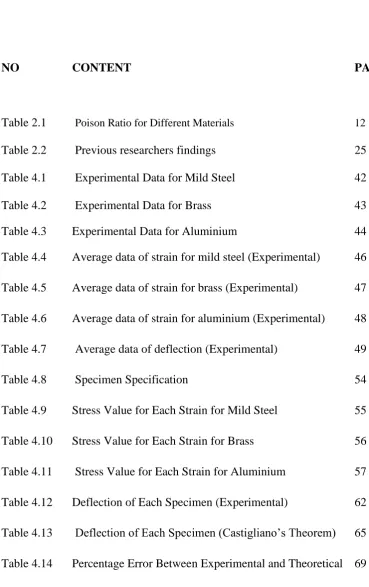
LIST OF TABLE
NO CONTENT PAGE
Table 2.1 Poison Ratio for Different Materials 12
Table 2.2 Previous researchers findings 25
[image:15.595.112.482.153.741.2]Table 4.1 Experimental Data for Mild Steel 42
Table 4.2 Experimental Data for Brass 43
Table 4.3 Experimental Data for Aluminium 44
Table 4.4 Average data of strain for mild steel (Experimental) 46
Table 4.5 Average data of strain for brass (Experimental) 47
Table 4.6 Average data of strain for aluminium (Experimental) 48
Table 4.7 Average data of deflection (Experimental) 49
Table 4.8 Specimen Specification 54
Table 4.9 Stress Value for Each Strain for Mild Steel 55
Table 4.10 Stress Value for Each Strain for Brass 56
Table 4.11 Stress Value for Each Strain for Aluminium 57
Table 4.12 Deflection of Each Specimen (Experimental) 62
Table 4.13 Deflection of Each Specimen (Castigliano’s Theorem) 65
Table 4.14 Percentage Error Between Experimental and Theoretical 69
Table 4.15 Deflection for Mild Steel with different support width 71
Table 4.16 Deflection for Brass with different support width 72
xv
LIST OF FIGURE
NO CONTENT PAGE
Figure 1.1 Beam Bridge or Girder Bridge Construction 2
Figure 1.2 I Beam in the Bridge Structure 2
Figure 2.1 I Beam Part 8
Figure 2.2 Stress – strain curve showing typical behaviour for non 13
ferrous alloys. Stress is shown as function of strain
Figure 2.3 Bending of I Beam 15
Figure 3.1 Project Methodology 28
Figure 3.2 Example of bend testing under a three-point bend 30
Arrangement
Figure 3.3 Basic installation of strain gauge 34
Figure 3.4 Bending stress of beam 36
Figure 3.5 Positive and negative area of i beam 37
ANNOTATION AND ABBREVIATION
UTS = Ultimate Tensile Strength
TS = Tensile Strength
Pa = Pascal Mpa = Megapascals
SMYS = Specified Minimum Yield Strength
UteM = Universiti Teknikal Malaysia Melaka
mm = Milimeter
m = Meter
kg = Kilogram
g = Gram
N = Newton
kN = Kilo Newton
xvii
LIST OF APPENDIX
BIL. TITTLE PAGE
A Poster of Seminar 1 90
B Slideshow of Presentation 1 91
C I Beam Data 92
CHAPTER 1
INTRODUCTION
1.1 BACKGROUND
A bridge is a structure that connects a gap for example river, roadway, and
valley for giving access to people and moving vehicles to places which beforehand
were not available to access in the first place. For example to cross a river and get to
the other side (Blagovest, 2004). The traffic that uses a bridge consist of people or
vehicles. There are many type of bridge depend on it purpose and use. The common
type of bridges are beam bridge, cantilever bridge, truss bridges and arch bridges.
The design are accounted depending on the the action of the bridge, the attributes of
the area area the bridge is constructed, the actual acclimated to accomplish it and the
funds accessible to body it. The failure of bridges is one of main concern
for structural engineers and contractor in trying to improve bridge design,
construction and maintenance (Blagovest, 2004). The important things is the bridge
should be designed such that it is safe, aesthetically pleasing, and conservative as it
involve the lives of people that use it when something happen to the bridge.In the
construction of pre-tensioned or post-tensioned beam bridges, a very common
problem that most contractors faced was to actuate and estimate the actual upward
deflection of beams due to prestressing (Loo, 2010). In other word, we need to able
to estimate the deflection of beam in the sturucture due to bending. From the
statements above, the objectives were stated as to design the ideal shape of I beam, to
determine the strain stress behavior using strain gauge for different materials and To
2
Stress-strain analysis of a material is restricted to confirm a large number of
its physical properties. With the information progressed through much investigation,
one can foresee how a material structure will respond when a loads are placed on it.
This can be proved when the results obained from this experiment give the desired result which same with the theorem statement. As the Castigliano’s Theorem state
that the deflection and strain is inversely proportional to Young Modulus, the results
are also give the same flow as the I Beam from mild steel give the better result inn
strain and deflection compared to brass and aluminium.
A diagnostic fix in few push elastic - plastic speculation is exhibited for the
immaculate bowing shaft under minor twisting. This fix recognizes the impacts of
both versatile distortion and plastic deformation,and gives the connection between the instant M and the arch κ verifiably (Jin and Chen, 2010). There are countless
different types of beam designs and materials in the market at the point that
composing a structure. Engineer and contractor can choose different shapes, sizes,
development materials, and development methods depend on suitability of
construction.. Settling on the best materials and shape for a specific structure could
be a muddled process. Structural designers and manufacturers have countless
different types of beam designs and materials when endeavoring to make an
structural configuration. Measuring bending stress is a main part of structural
designing. Measuring bending stress confirms what amount of burden a structure
can loads before it failed. Assembling structurally sound ventures is the main
objective of succesfull structural designing (Loo, 2010).
1.2 PROBLEM STATEMENT
Research show that many applications have limitation on the amount of
deflection that can be tolerated especially in a sturcture (Roylance, 2000). The
structure will face a collapse or failure when the the amount of deflection exceeded.
in daily life or during the accident occurs. The development of extensions is the
consequence of a blend of infrastructures in development materials, structural
shapes, what is more configuration and dissection strategies. Composite structures
were acquainted with serve as a greatly aggressive sort of connect equivalent to
regular sorts of extensions for example cement and prestressed solid scaffolds
because of their lessened weight and snappy and practical erection (Hayward et al.
1988). Therefore the prediction of deflection is important and must be studied. The
prediction of deflection is one of part of structure analysis. When deciding to analyze
the structure, engineer must know the basic part and concept of structure. In
engineering, a structre is defined as a body or assemblage of bodies that capable to
support loads. The structure elements or part are column,beam and trusses. There are
a few method of structural analysis which are elasticity method, numerical
approximation method and material strength method (Felipa, 2000). The most
popular or close with deflection tolerate are bending. There are many researchers
have been done related to subjected bending for analyzing the strain stress behavior
of the specimen. They usually use the size, design and materials as their variables.
The researches commonly focused on the bar shape because it is the basic shape.
Therefore, this report will change the shape to the I Beam shape as realize the shape
is extensively used in construction such as rail train, bridge and buildings. This report
will focused on materials as variable by use mild steel, brass and aluminum as the
main material of specimens. The choice of these three types of materials is that
because this material is often used in the construction industry.
1.3 OBJECTIVE
The aim of this study is to analysis the I beam subjected to three point
bending for different materials in term od strain stress and deflection.
The objective of this project is as follow:
4
2. To determine the strain stress behavior using strain gauge for different materials.
3. To investigate the deflection of beam between experiment and theory with by using Castigliano’s Theorem method and Strain Energy Method.
1.4 SCOPE
The scope of the study will implement a few of confinements and
specifications. Firstly is to design the ideal shape of i beam in real application. I
beam shape was selected to analyze as i beam used extensively as reinforcement to a
structure especially bridge. Then, analyze I beam based on three different materials
which are mild steel, brass and aluminium. This experiment also will use strain
gauge to measure strain for each material. The study based on experiment will
conducted at Structure and Materials Laboratory in Universiti Teknikal Malaysia
Melaka (UTeM). Lastly, the dimension of I Beam is limited to 300 mm x 30 mm x
30 mm as equipment limitation.
1.5 SUMMARY OF THE PROJECT
This project are divided into two parts which are Projek Sarjana Muda (PSM)
1 and PSM 2. PSM 1 consists of three chapters which are introduction, literature
review and methodology. Introduction discusses on the definition, objectives, scope
and problems statement related to the project. Literature review will explain in term
of fundamental, method and measurement used to gain the result. Methodology make
up of the technique used in obtaining the data of experiment. Result and discussion
will be explained in PSM 2. Result and discussion mainly explain about the result
and how the data is being analyzed after the implementation of work study. The final
chapter is conclusion and the objectives that had been determined before will be
1.6 BENEFIT OF PROJECT
There are many benefit of this project. The report can help the engineer to
estimate the suitable material for the construction. This is because the dimension of I
beam specimen is made according the ratio of the real I beam in the structural field.
Then, this report will guide the engineer in investigating the two major of beam
characteristics which are strength and stiffness. Strength describes how much load
the beam can carry where stiffness describes how much beam deflects when loaded.
So, by this researched, engineer can know how much force any structural member
can take before it will deform or break.
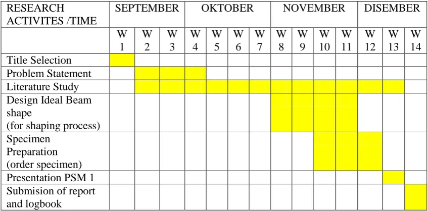
[image:24.595.107.531.397.606.2]1.7 PLANNING AND EXECUTION
Table 1.1 : Gantt Chart of PSM 1 Research
RESEARCH ACTIVITES /TIME
SEPTEMBER OKTOBER NOVEMBER DISEMBER W 1 W 2 W 3 W 4 W 5 W 6 W 7 W 8 W 9 W 10 W 11 W 12 W 13 W 14 Title Selection Problem Statement Literature Study Design Ideal Beam shape
(for shaping process) Specimen