i
AUTOMATIC TROLLEY HUMAN FOLLOWER
AMIR HAFIZUL BIN ABD MALEK
This Report Is Submitted In Partial Fulfillment of Requirement for the Bachelor Degree of Electronic Engineering (Industrial Electronic) with Honours
Faculty of Electronic and Computer Engineering Universiti Teknikal Malaysia Melaka
ii
DECLARATION
“I declare that this report “Automatic Trolley Human Follower” is the result of my own research except as cited in the references”
Signature : ………. Author : AMIR HAFIZUL BIN ABD MALEK
iii
“I hereby declare that I have read this report entitled “Automatic Trolley Human Follower” and it fulfills the requirements of the scope and quality for the Bachelor of
Electronic Engineering (Industrial Electronic) with Honours”
Signature : ………...
Supervisor’s Name : ENGR. NAJMIAH RADIAH BINTI MOHAMAD
iv
Special dedicate:
To my beloved mother Zainun Binti Ismail and my family for their loves and prayers. To my supervisor and co-supervisor for their guide and give moral support
v
ACKNOWLEDGEMENT
I would like to express my gratitude and appreciation to all those who gave me the support to complete this “Automatic Human Follower trolley” thesis. A special thanks to my final year project supervisor Madam Najmiah Radiah Binti Mohamad who give suggestion and encouragement, helped me to coordinate my project especially in writing this report.
I would like to acknowledge with much appreciation the crucial role of staff of laboratory, who gave the permission to use all required machinery and the necessary material to complete this project.
vi
ABSTRACT
vii
ABSTRAK
viii
TABLE OF CONTENTS
CHAPTER TITLE PAGES
TITLE PAGE i
DECLARATION iii
DEDICATION v
ACKNOWLEDGEMENT vi
ABSTRACT vii
ABSTRAK viii
TABLE OF CONTENTS ix
LIST OF TABLES xiii
LIST OF FIGURES xiv
LIST OF ABBREVIATIONS xvii
I INTRODUCTION
1.1 Introduction 1
1.2 Problem Statement 2
1.3 Objectives 2
1.4 Scope of the project 3
II LITERATURE REVIEW
2.1 Introduction 4 2.1.1 Radio Frequency based Remote 4
Operated SPY Robot
ix
Team
2.1.4 Infrared Sensor Based Target 7
Following Device for a Mobile Robot 2.1.5 Detecting and Tracking People 8
by Mobile Robot Using Structured Light Range Sensor 2.1.6 Robot Tracking Using Vision and 9
III METHODOLOGY 3.1 Introduction 10
3.2 Illustration of Project Design 11
3.3 Overview of the Project Development 12
3.4 Project Operation 13
3.4.1 Automatic Mode 13
3.4.2 Manually Mode 16
3.5 Circuit Design 19
3.5.1 Ultrasonic Transmitter Module Design 19
3.5.2 Ultrasonic Receiver Module Design 20
3.5.3 Infra Red (IR) Module Design 22
3.5.4 Motor Drive Module Design 22
3.5.5 Main Microcontroller Module Design 25
IV RESULT AND DISCUSSION 4.1 Introduction 27
4.2 Hardware Result 27
4.2.1 Trolley Design Measurement Frame 27
x
4.2.3 Relay circuit result 29 4.2.4 Ultrasonic Sensor Result 31 4.2.5 IR Sensor Result 32 4.2.6 Radio Frequency Remote Control Result 34 4.3 Measurements of IR Sensor 34 4.4 Measurements the Speed of the Trolley 35 4.4.1 Measurement the Speed of the Trolley in 36 Straight Line
4.5 Discussion and Analysis 37 4.5.1 Analysis of IR Sensor Result 37 4.5.2 Analysis of the Speed of the Trolley Due 37 To the Load
V CONCLUSION AND RECOMENDATION
5.1 Conclusion 39 5.2 Recommendation 40
REFERENCES
xi
LIST OF TABLES
NO TITLE PAGES
xii
LIST OF FIGURES
NO TITLE PAGES
2.1 Radio Frequency based Remote Operated SPY Robot 5
2.2 Design of Forklift Robot 6
2.3 Human Leader and Robot Follower Concept 7
2.4 IR Sensor Range 7
2.5 Mobile Robot Using Structured Light Range Sensor 8
2.6 Robot Tracking Following a Person 9
3.1 Illustration Version of trolley design 11
3.2 A System Flow 12
3.3 Overview of project operation (automatic mode) 13
3.4 Flowchart of project operation (automatic mode) 14
3.5 Overview of project operation (manually mode) 16
3.6 Flowchart of project operation (manually mode 17
3.7 Schematic of ultrasonic transmitter 19
3.8 PCB Wizard Circuit of ultrasonic transmitter 20
3.9 Schematic Circuit of ultrasonic receiver 21
3.10 PCB Wizard Circuit of ultrasonic receiver 21
3.11 Schematic circuit of infra red 22
3.12 Schematic Circuit of 5V motor drive 23
3.13 PCB Wizard Circuit of 5V motor drive 23
xiii
3.15 PCB Wizard Circuit of 12V motor drive 24
3.16 Schematic circuit of PIC 25
3.17 PCB Wizard circuit of PIC 25
4.1 Measurement Frame of the Trolley 28
4.2 Main circuit with PIC microcontroller 29
4.3 12V Relay Circuit 30
4.4 5V Relay Circuit 30
4.5 Ultrasonic Receiver Circuits 31
4.6 Ultrasonic Transmitter 32
4.7 IR Sensor Circuit 33
4.8 IR Sensor Comparator Circuit 33
4.9 RF Remote Control module Circuit 34
xiv
LIST OF ABBREVIATIONS
DC - Direct Current IC - Integrated Circuit IR - Infrared
PIC - Peripheral interface controller PTZ - Pant-Tilt-Zoom
RFID - Radio Frequency Identification Device SL - Structured Light
1
CHAPTER I
INTRODUCTION
1.1 Introduction
Nowadays, most of the things in this world use the technology for more productive life. The people always find something to help them doing a works rather doing them self because of their busy life. However, this new technology which is designed for shopping or carrying heavy thing has never used before. Trolley is a large metal basket or frame on wheels is used for transporting heavy or large items, such as supermarket purchases or luggage at an airport or railway station and transferring a heavy item in industry. By using a trolley, humans do not need to feel bothered and will not get tired for carrying goods although it are quite lot. In manual trolley, human labor is still required to utilize trolley. They still need to push the trolley or bring the basket to bring the stuff. So, if there is a trolley that can be run automatically, then bring the stuff will be easier and efficient.
2
1.2 Problem Statement
From the observation on retail and industrial sector, there is a lot of people in Malaysia are still using manual trolley to carry heavy thing. Most of them do not expose to an automatic trolley technology for replacing existing tools and improve the quality of services. Accordingly, these technologies have been establish to carrying tools that too heavy, that its uses a lot of energy to push the trolley [2].
The innovation of automatic trolley can evade from injury to user because repetitive or sustained awkward posture when handling trolley can cause injury [2]. Furthermore, the manual trolley is not user friendly to pregnant woman and disables people. There was an accident involved uncontrolled trolley which one old woman died in China because of that manual trolley was slides down form an escalator [3].
1.3 Objectives
The main objectives of this project are
i. To design and produce a versatile trolley that is user friendly for human and makes their life more productive.
ii. To produce automatic trolley that can carry a heavy thing to move from one point to another point.
3
This project is focusing a trolley that can be use in hypermarket or industries that automatically follow the user to shopping and carry thing. The versatile design of this trolley can be transform into two versions.
This Automatic Trolley Human Follower target is general user and industry uses. For general user, this trolley are focusing to help a user when they are shopping in hypermarket .The user does not need to worry about the trolley that carry their items and they can focus on their shopping. The trolley can follow the user in specific range and it not follows the user too close.
For the industrial use, the target point is to help industry that need carry heavy tools to move from one point to another point. This trolley can thus reduce the manpower. When their need to carry a heavy tools, it can be handled just by one labor because this trolley can follow the labor. So, It can reduce the cost of workers hired.
The versatile design of trolley can help workers carry up to 100kg of thing. The Automatic Trolley Human Follower was designed using 4 wheel trolleys and focusing on back wheel that connect 12 volt dc motor to move on the trolley. The trolley distance about 0.5 meters from user or obstacle. The process to the overall for this robot is controlled and setting by the PIC 16F877A.
4
CHAPTER II
LITERATURE REVIEW
2.1 INTRODUCTION
By design the suitable Automatic Trolley Human Follower for the applications that desired, the decision has been made from a combination of some robots follower that has nowadays with a manual trolley that existing. These are some robots followers that have a guideline to design the Automatic Trolley Human Follower.
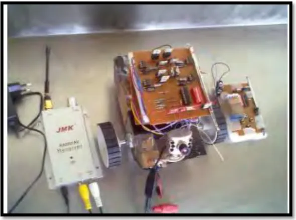
2.1.1 Radio Frequency based Remote Operated SPY Robot
5
Figure 2.1: Radio Frequency based Remote Operated SPY Robot
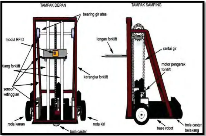
2.1.2 A Mini Forklift Robot
6
Figure 2.2: Design of Forklift Robot
2.1.3 Human Leader and Robot Follower Team
7
Figure 2.3: Human Leader and Robot Follower concept
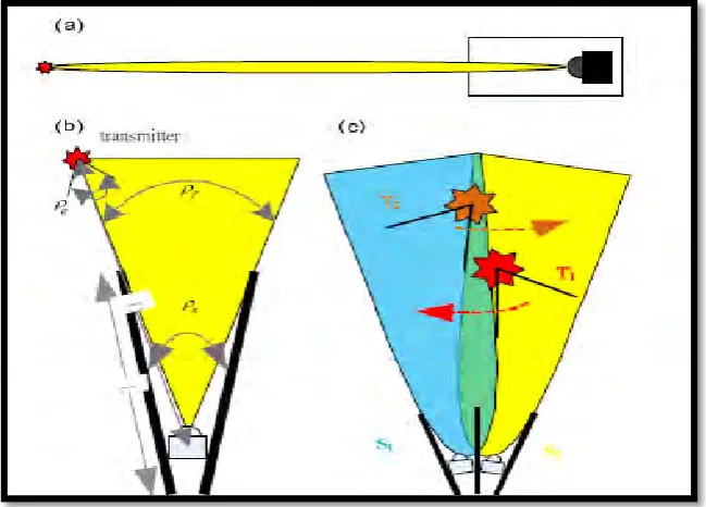
2.1.4 Infrared Sensor Based Target Following Device for a Mobile Robot
Based Youg Jen Wen et al. was report the sensory setup and algorithm for target following on the mobile robot. The direction detection of the target is achieved by the setup of nine IR receivers which monitor the signals from the transmitter installed on the target [7].A IR sensor is not accurate compare to the ultrasonic sensor. Figure 2.4 was show the IR Sensor range.
[image:21.595.155.480.513.746.2]8
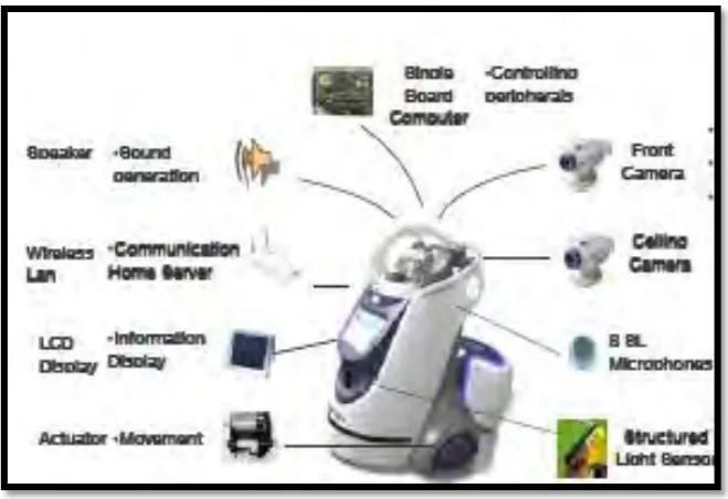
2.1.5 Detecting and Tracking People by Mobile Robot Using Structured Light Range Sensor
[image:22.595.152.482.339.565.2]In Young jinn Hong et al. was introduced a home robot to keep track of moving people in home environments. A SL range sensor is utilized in light of its high commercial viability. The sensors typically have relatively short measurement range and poor range resolution at a long distance (within 4 meters in our case). These shortcomings raise some problems that feature detection process gives many human legs candidates making it difficult to discriminate the real human legs from other patterns [8].The sensors typically have relatively short measurement range and poor range resolution at a long distance. Figure 2.5 show the Mobile Robot Using Structured Light Range Sensor.
9
2.1.6 Robot Tracking Using Vision and Laser Sensor
[image:23.595.195.442.365.576.2]Wen Dai et al. was presents a real-time person tracking system for a mobile robot using the information from a PTZ video camera and a laser range finder. The model includes the color, edge and size information of the tracked person. People moving in the field of view are detected by the robot via the laser range finder and verified against the target person model using the images captured by onboard camera. A practical filter is used to estimate the position and the velocity of moving target person for controlling the robot to follow the target [9].However, the laser sensor can only detect in straight position. So, the range of the detected is small. Figure 2.6 was show the Robot Tracking Following a Person.
10
CHAPTER III
METHODOLOGY
3.1 Introduction
There are four parts in this methodology process. First, the illustration of project design that show dimension of vehicle frame. Second, it is about the overview of the project development. Third, the project operation which is consist a manual and automatic mode. Fourth, the circuit design, that show a module design that are used in the making of this project.
3.2 Illustration of Project Design
This trolley frame has been designed by using some material, such as iron frame, and four wheels. The figure 3.1 shows the dimension of the vehicle frame for length, width and height. The frame that has been design has 75 cm length, 50 cm width and 60 cm height. . The figure 3.1 also shows the placement of IR sensor, Ultrasonic sensor and main circuit box.