Int. J. Electrochem. Sci., 7 (2012) 1180 - 1186
International Journal of
ELECTROCHEMICAL
SCIENCE
www.electrochemsci.org
Improved Electrochemical Performance of Sn–Ni Nanorods
Array for Li-ion Battery
Zhijia Du, Shichao Zhang*, Jianfeng Zhao, Tao Jiang, Zhiming Bai
School of Materials Science and Engineering, Beihang University, Beijing, 100191, China
*
E-mail: [email protected], [email protected]
Received: 29 November 2011 / Accepted: 14 January 2012 / Published: 1 February 2012
Sn–Ni nanorods electrode supported by nanocones array was prepared via a facile two-step electrodeposition method. The morphology and phase structure were characterized by scanning electron microscopy and X-ray diffraction, respectively. Cyclic voltammogram and galvanostatic charge/discharge testing were carried out to evaluate the electrochemical performance. The specific nanorods array design functioned well in accommodating the volume expansion and strengthening the interfacial force between active materials and current collector. The Sn–Ni nanorods array electrode showed a high discharge capacity of ~500 mAh g-1 and excellent cycling stability. Furthermore, the nanopore evolution in Sn–Ni nanorod after cyclic lithiation/delithiation process was reported for the first time.
Keywords: Sn–Ni alloy; nanorods array; Li-ion battery; electrodeposition; porous materials
1. INTRODUCTION
The exploration of high capacity, long lifespan Li-ion battery has been given many research efforts in the last two decades [1,2]. Tin has been targeted to replace graphite as the anode material for Li-ion battery due to its high theoretical capacity of 994 mAh g-1 [3,4]. However, the commercial implementation of Sn-based anode materials was hindered by the drastic capacity decay during cycling owing to the enormous volume expansion of ~300% [3,5]. To circumvent this defect, various Sn-based intermetallics or composites have been proposed and used as anode materials such as Sn–Cu [6], Sn– Co [7], Sn–Ni [8], etc. It was found that these systems exhibited some improvement in capacity retention but far from desirableness. In J. Hassoun’s report [8], various samples of NixSny metallic
It is now recognized that optimization of the electrode configuration is also very important as discussed in previous report [9,10]. The reported nano-architectured electrode designs enlarged the contact surface area between the active materials and the electrolyte; moreover, they were very competent to alleviate the intensive stress during charge/discharge process. Recently, we have constructed a novel Si architecture supported by Ni nanocones array as the anode material for the first time [10]. In this layout, the Ni nanocones functioned as effective electron pathways, good mechanical supports and efficient confining cushions, which resulted in attractive cycle performance and rate capability.
In this report, Sn–Ni nanorods array electrode was prepared by a facile two-step electrodepostion method. It was demonstrated that the obtained Sn–Ni nanorods array electrode exhibited appealing advancement of Li+ storage property for high capacity and long lifespan. Furthermore, interesting nanopore evolution was observed in the repeat lithiation/delithiation process on the surface of Sn–Ni nanorods.
2. EXPERIMENTAL SECTION
Ni nanocones array was fabricated as described in our previous report [10]. The electrodes were prepared by electrodepositing Sn–Ni alloy onto Ni nanocone arrays. The electrolytic bath consisted of analytical pure 0.15 M SnCl2·2H2O, 0.1 M NiCl2·6H2O, 0.5 M K4P2O7·3H2O. The
temperature of deposition solution was maintained at 55 oC. The deposition current density was 5 mA cm-2 with deposition time of 5 min. After deposition, the samples were rinsed in deionized water for several times and then dried in vacuum at 80 oC.
The morphologies and phase structure of the electrodes were investigated by field emission scanning electron microscopy (FE-SEM, Hitachi S-4800 SEM system) and MAC Science X-ray diffraction (Cu Kα radiation). Elemental analysis was performed using energy-dispersive X-ray
spectroscopy (EDX) in conjunction with the SEM. Electrochemical charge–discharge behaviours were investigated in half-cells composed of the as-deposited electrode, Li foil and Celgard 2300 membrane in an Ar filled glove box. 1 M LiPF6/EC−DEC (1:1 by vol.%) was used as the electrolyte. Cyclic
voltammogram (CV) test was performed between 0 and 3.0 V (vs. Li/Li+) at 0.1 mV s−1 via a Zahner electrochemical workstation (iM6ex). The galvanostatic charge–discharge measurements were conducted at room temperature with cut-off voltage of 0.05−1.5 V.
3. RESULTS AND DISCUSSION
Sn–Ni nanorod is about 250 nm. The obtained electrode was composed of uniformly packed Sn–Ni nanorods array in line with the nanocones array substrate. Meanwhile, it is obvious there are enough spaces between adjacent Sn–Ni nanorods from both the top view (Fig. 1c) and the 45o side view (inset of Fig. 1c). To confirm that active materials Sn has been deposited on the nanocones, EDX was carried out and the spectrum confirmed the dominant Sn, Ni and Cu signals from the electrode.
Figure 1. (a), SEM image of as-prepared Ni nanocones array; (b) and (c), low and high magnification SEM images of Sn–Ni alloy electrode deposited on Ni nanocones array for 5 min, the inset of (c) is from 45o side view; (d), EDX spectrum of Sn–Ni nanorods array.
[image:3.596.59.540.180.556.2]
Figure 2. XRD patterns of (a) the nickel nanocones array and (b) the Sn–Ni nanorods array electrode.
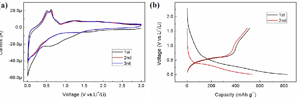
The obtained Sn–Ni nanorods array was directly assembled into half cells with Li metal as the counter electrode. Fig. 3a displays the cyclic voltammogram of the electrode to investigate the reaction mechanism between Li and Sn–Ni alloy. In the first cathodic process, it shows that a irreversible broad slop located at 1.20–0.50 V, which was associated with the reduction of some impure oxides and the decomposition of electrolyte with the formation of solid electrolyte interface (SEI) layer on the pristine electrode surface [11-13]. The charge current related to the lithiation of Sn–Ni alloy and the formation of LixSn alloy began at 0.50 V and became quite large up until 0.01 V. Upon anodic scan, two
delithiation peaks appeared at around 0.56 and 0.63 V, which was assigned to the delithiation process of LixSn [14,15]. All the subsequent cycles are reproducible and almost overlapping, representing the
steady reversible lithiation/delithiation process of LixSn.
Figure 3. (a) Cyclic voltammogram of Sn–Ni nanorods array for the first three cycles; (b) Voltage profiles of the electrode cycled between 10 mV and 1.6 V at 0.5 C rate.
[image:4.596.53.539.491.653.2]
charge of the anode, respectively. Large irreversible capacity generated above 0.50 V in the first discharge may be resulted from the reduction of possible oxide impurities and the formation of SEI on the electrode surface, since the large specific area of the nanorods array can consume much capacity for SEI [16]. After the first discharge, the profile of both charge and discharge showed sloping characteristic due to the active/inactive structure of Ni3Sn4 intermetallic as reported before [17,18].Cycling performance of the cell with Sn–Ni nanorods array as electrode at a rate of C/2 is depicted in Fig. 4, directly interpreting the excellent electrochemical performance of Sn–Ni nanorods array electrode. At the first cycle, the discharge and charge capacity are measured 826 mAh g-1 and 514 mAh g-1, respectively. Despite the low value of 62% in the first cycle due to the decomposition of electrolyte and the irreversible Li+ insertion into the electrode, the Coulombic efficiency soared to a relatively high level in the following cycles (ca. 95% for cycles 4–60). The discharge and charge capacity of Sn-Ni nanorods array maintained well in the following cycles. For example, the reversible capacity after 40 cycles is 492 mAh g-1 with retention rate of 95.9%, and that after 60 cycles is still 461 mAh g-1 with retention rate of 89.8%. The Li+ storage capability of the Sn–Ni nanorods array is superior to the previous reported Sn–Ni electrode [8,19–21], which verifies the advantage of the novel electrode configuration of Sn–Ni nanorods array. The remarkable cycling stability is assigned to the well-designed Sn–Ni nanorods array architecture in which the inactive Ni matrix of Ni3Sn4
intermetallic as well as the space betweeen adjacent Sn–Ni nanorods cushioned the enormous volume expansion and the concomitant stresses during cyclic lithiation/delithiation process. Moreover, the fact that the Ni nanocones sandwiched between the current collector and the active materials enhanced the bonding force by anchoring the Sn–Ni nanorods, which also was favorable for the hinderance of electrode degradation and capacity fading [10].
Figure 4. Capacity and Coulombic efficiency versus cycle number for the Sn–Ni nanorods array.
[image:5.596.121.477.466.673.2]
specific electrode design was beneficial for the tolerance of volume expansion. Moreover, the nanoporous structure evolution was revealed on examining the high magnification SEM image of Fig. 4b. This phenomenon is attributed to the dealloying process, which was previous reported as a common corrosion process. In this process, the more electrochemically active part was selectively dissolved with the formation of a nanoporous sponge composed of the nobler alloy constituents [22]. The delithiation of Li from LixSn alloy can be ascribed to the Li dealloying process which has also
been reported as nanopore evolution in one-dimensional silicon and germanium nanostructures [23,24]. During charging, the extraction of Li possibly causes the formation of void pores in the Sn–Ni nanorods. To date, this is the first report on the nanopore evolution in Sn-based intermetallic anode materials. The obtained nanoporous Sn-Ni nanorods array was expected to use in many potential applications such as catalysts and supercapacitors [23,25].
Figure 5. (a) Low and (b) high magnification SEM images of the electrode after cyclic lithiation/delithiation.
4. CONCLUSION
In summary, Sn–Ni nanorods array has been successfully fabricated with Ni nanocone-array as the current collector. The electrode after deposition of Sn–Ni alloy for 5 min were composed of many nanorods with average diameter of ~250 nm. XRD indicated that the deposited Sn–Ni alloy was Ni3Sn4
intermetallic phase. In this electrode configuration, these Ni cones functioned as structure support, electron transport paths and interfacial anchors. Meanwhile, the space among Sn–Ni nanorods accommodated the volume expansion. Sn-Ni nanorods array showed superior cycling capability, with 89.8% capacity retained of 461 mAh g-1 after 60 cycles. Besides, the nanopore evolution was revealed in Sn-based electrode for the first time.
ACKNOWLEDGEMENTS
[image:6.596.73.527.282.452.2]
2008AA03Z208), and the Innovation Foundation of BUAA for PhD Graduates as well as the Scholarship Award for Excellent Doctoral Student granted by China Ministry of Education.
References
1. M. Armand and J.-M. Tarascon, Nature 451 (2008) 652. 2. J. B. Goodenough and Y. Kim, Chem. Mater. 22 (2010) 587. 3. M. Winter and J. O. Besenhard, Electrochim. Acta 45 (1999) 31.
4. I. A. Courtney, J. S. Tse, O. Mao, J. Hafner, and J. R. Dahn, Phys. Rev. B 58 (1998) 15583. 5. L. Y. Beaulieu, K. W. Eberman, R. L. Turner, L. J. Krause, and J. R. Dahn. Electrochem. Solid
State Lett. 4 (2001) A137.
6. K. D. Kepler, J. T. Vaughey, and M. M. Thackeray, J. Power Sources 81–82 (1999) 383. 7. J. J. Zhang and Y. Y. Xia, J. Electrochem. Soc. 153 (2006) A1466.
8. J. Hassoun, S. Panero, and B. Scrosati, J. Power Sources 160 (2006) 1336.
9. J. Hassoun, S. Panero, P. Simon, P. L. Taberna, and B. Scrosati, Adv. Mater. 19 (2007) 1632. 10.S. Zhang, Z. Du, R. Lin, T. Jiang, G. Liu, X. Wu, and D. Weng, Adv. Mater. 22 (2010) 5378. 11.N. Tamura, Y. Kato, A. Mikami, M. Kamino, S. Matsuta, and S. Fujitani, J. Electrochem. Soc. 153
(2006) A2227.
12.A. D. W Todd, R. E. Mar, and J. R. Dahn, J. Electrochem. Soc. 153 (2006) A1998. 13.N. Pereira, L.C. Klein, and G.G. Amatucci, Solid State Ionics 167 (2004) 29.
14.L. Huang, H.-B.Wei, F.-S. Ke, X.-Y. Fan, J.-T. Li, and S.-G. Sun, Electrochim. Acta 54 (2009) 2693.
15.I. Amadei, S. Panero, B. Scrosati, G. Cocco, and L. Schiffini, J. Power Sources 143 (2005) 227. 16.F. Ke, L. Huang, H. Jiang, H. Wei, F. Yang, and S. Sun, Electrochem. Comm. 9 (2007) 228. 17.A. D. W. Todd, P. P. Ferguson, M. D. Fleischauer, and J. R. Dahn, Int. J. Energy Res. 34 (2010)
535.
18.Z. Du, S. Zhang, Y. Xing, and X. Wu, J. Power Sources 196 (2011) 9780– 9785. 19.X.-Q. Cheng and P.-F. Shi, J. Alloys Compd. 391 (2005) 241.
20.K. Nishikawa, K. Dokko, K. Kinoshita, S.-W. Woo, and K. Kanamura, J. Power Sources 189 (2009) 726.
21.X.-Z. Liao, Z.-F. Ma, J.-H. Hu, Y.-Z. Sun, and X. Yuan, Electrochem. Comm. 5 (2003) 657. 22.J. Erlebacher, M. J. Aziz, A. Karma, N. Dimitrov, and K. Sieradzki, Nature 410 (2001) 450. 23.J. W. Choi, J. McDonough, S. Jeong, J. S. Yoo, C. K. Chan, and Y. Cui, Nano Lett. 10 (2010)
1409.
24.X. H. Liu, S. Huang, S. T. Picraux, J. Li, T. Zhu, and J. Y. Huang, Nano Lett. 11 (2011) 3991. 25.H. Xia, M. O. Lai, and L. Lu, J. Power Sources 196 (2011) 2398.