UNIVERSITI TEKNIKAL MALAYSIA MELAKA
Terminal Identifier Design for Single Phase AC Motor using
Microcontroller-based Voltmeter
This report is submitted in accordance with the requirement of Universiti Teknikal
Malaysia Melaka (UTeM) for the Bachelor of Electrical Engineering Technology
(Industrial Automation & Robotics) with Honours.
By
MUHAMMAD AMIRUL FAEZ BIN RAMLAN B071310248
910519-14-6405
FACULTY OF ENGINEERING TECHNOLOGY
UNIVERSITI TEKNIKAL MALAYSIA MELAKA
BORANG PENGESAHAN STATUS LAPORAN PROJEK SARJANA MUDA
TAJUK: Temperature Controlled Device for Medical Application by Using Peltier Effect
SESI PENGAJIAN: 2016/17 Semester 1
Saya MUHAMMAD ERWAN SHAH BIN ABDULLAH
mengaku membenarkan Laporan PSM ini disimpan di Perpustakaan Universiti Teknikal Malaysia Melaka (UTeM) dengan syarat-syarat kegunaan seperti berikut: 1. Laporan PSM adalah hak milik Universiti Teknikal Malaysia Melaka dan penulis. 2. Perpustakaan Universiti Teknikal Malaysia Melaka dibenarkan membuat salinan
untuk tujuan pengajian sahaja dengan izin penulis.
3. Perpustakaan dibenarkan membuat salinan laporan PSM ini sebagai bahan pertukaran antara institusi pengajian tinggi.
4. **Sila tandakan ( )
SULIT
TERHAD
TIDAK TERHAD
(Mengandungi maklumat yang berdarjah keselamatan atau kepentingan Malaysia sebagaimana yang termaktub dalam AKTA RAHSIA RASMI 1972)
(Mengandungi maklumat TERHAD yang telah ditentukan oleh organisasi/badan di mana penyelidikan dijalankan)
Alamat Tetap:
NO. 9 KAMPUNG PAUH,
BUKIT GANTANG, 34850 TAIPING PERAK DARUL RIDZUAN
Tarikh: 05 / 01 / 2017
Disahkan oleh:
Cop Rasmi:
DECLARATION
I hereby, declared this report entitled “Terminal Identifier Design for Single Phase
AC Motor using Microcontroller-basedvoltmeter” is the results of my own research
except as cited in references.
Signature : ………
Author’s Name : MUHAMMAD AMIRUL FAEZ BIN RAMLAN
APPROVAL
This report is submitted to the Faculty of Engineering Technology of UTeM as a
partial fulfillment of the requirements for the degree of Bachelors of Electrical
Engineering Technology (Industrial Automation & Robotics) with Honours. The
member of the supervisory is as follow:
………
v
ABSTRAK
vi
ABSTRACT
This device is developed by using microcontroller based on circuit for terminal identifier of single phase alternate current (AC) motor and purposely to make user can easily identify the terminal motor instantly. Quite often, AC motor manufacturer does not provide marking of motor terminals. Furthermore, there is no standard of wire color motor terminals has been enacted in industry. These problems have obscure the motor terminal identification especially by repair technician during troubleshooting process or motor replacement work. Even though the identification of this motor terminal can be done by using ohmmeter of a multimeter, but it is less appropriate in term of user interface. A user has to measure the resistance across terminal of the motor and decide the terminal labels based on obtained resistance value. This process is time consuming and prone to decision error. Hence, a simpler way of determining the terminals of an AC single phase which posses a better user interface is developed the device is designed to have three probes; first probe is connected to 5v power supply and the other two probes is connected to ground. Each probe is presented by single digit of seven segment display to show the terminal name when the probe is connected to terminal of the motor. These probes also is connected to the analog–to-digital-converter (ADC) port of microcontroller to prepare the identifying algorithm. The probes of the device is connected to testing AC motor, subsequently several inequality rules can be produced based on the obtained ADC value. However, not all possible probe connection to the terminal can be covered by inequality rules, therefore the feature of ‘probe rotation required’ indicator is added. It the end of the project, the developed device successfully identify the motor terminal of single phase AC motor when the probes is connected to the input terminal.
vii
DEDICATION
To my beloved parents
To my kind supervisors
And not to forget to all my fellow friends
viii
ACKNOWLEDGEMENT
Before, while and after I doing my job to complete this project, I have
received so many help from my supervisors, lecturers, researchers, family members
and also my fellow friends.
First and foremost, I want to give my thanks to my supervisor, Dr Mohd
Badril Bin Nor Shah who gave me a lot of encouragement, a true guidance and very
supportive.
Besides, I also thankful to my parents for supporting me on mentally and
financially for almost part for this project. It is the most things that I need.
Not forget also to my fellow friends, very kind housemates of “Rumah Ukhwah Fillah” that help me constantly with support, advices and technical skills.
Last but not least, thanks to all people those help me directly or indirectly.
ix
TABLE OF CONTENT
Abstrak v
Abstract vi
Dedication vii
Acknowledgement viii
Table of Content ix
List of Table xii
List of Figures xiii
CHAPTER 1: INTRODUCTION 1
1.0 Project Background 1
1.1 Problem Statement 3
1.2 Objectives 6
1.3 Work Scope 6
1.4 Thesis Outline 7
CHAPTER 2:LITERATURE REVIEW 8
2.0 Introduction 8
2.1 Microcontroller 8
2.1.1 Power 11
2.1.2 Memory 12
2.1.3 Input and output 12
2.1.4 Communication 14
2.1.5 Programming 14
2.1.6 Automatic (Software) Reset 15
2.1.7 USB Overcurrent Protection 16
2.1.8 Simulation 16
2.1.9 Proteus 8 Professional 17
2.1.10 Proteus PCB Design 17
x
2.2.1 The Loading Effect 20
2.3 Voltage Divider 22
2.4 DC Current Comparator Resistance Ratio Standard 23
2.5 The Automated Direct Current Comparator 24 2.6 High Precision Measurement of The Load Effect of The Resistor 26
2.7 Measurement Principle 27
2.8 Terminal Single Phase Ac Motor 30
CHAPTER 3: METHADOLOGY 32
3.0 Introduction 32
3.1 Circuit Design 33
3.1.1 Probes 33
3.1.2 Power Supply 33
3.1.3 Resistor 34
3.1.4 Seven Segment Display 34
3.2 Hardware Development 35
3.3 Identifying Algorithm Development 36
CHAPTER 4: RESULT AND DISCUSSION 38
4.0 Introduction 38
4.1 Circuit Simulation 38
4.2 Experimented Results 39
4.2.1 Experiment Case 0 40
4.2.2 Experiment Case 1 41
4.2.3 Experiment Case 2 42
4.2.4 Experiment Case 3 43
4.2.5 Experiment Case 4 44
4.2.6 Experiment Case 5 45
xi
CHAPTER 5: CONCLUSION AND RECOMMENDATION 47
5.0 Conclusion 47
5.1 Recommendation Of Future Work 47
REFRENCES 49
xii
LIST OF TABLE
Table 3.1 Inequality rule development 38
Table 4.1 Response of the device for case 0 41
Table 4.2 Response of the device for case 1 42
Table 4.3 Response of the device for case 2 43
Table 4.4 Response of the device for case 3 44
Table 4.5 Response of the device for case 4 45
Table 4.6 Response of the device for case 5 46
xiii
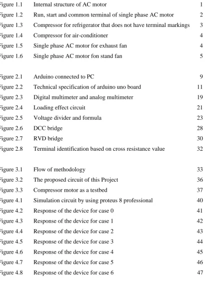
LIST OF FIGURES
Figure 1.1 Internal structure of AC motor 1
Figure 1.2 Run, start and common terminal of single phase AC motor 2
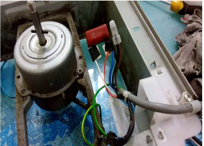
Figure 1.3 Compressor for refrigerator that does not have terminal markings 3
Figure 1.4 Compressor for air-conditioner 4
Figure 1.5 Single phase AC motor for exhaust fan 4
Figure 1.6 Single phase AC motor fon stand fan 5
Figure 2.1 Arduino connected to PC 9
Figure 2.2 Technical specification of arduino uno board 11 Figure 2.3 Digital multimeter and analog multimeter 19
Figure 2.4 Loading effect circuit 21
Figure 2.5 Voltage divider and formula 23
Figure 2.6 DCC bridge 28
Figure 2.7 RVD bridge 30
Figure 2.8 Terminal identification based on cross resistance value 32
Figure 3.1 Flow of methodology 33
[image:13.595.117.528.129.707.2]Figure 3.2 The proposed circuit of this Project 36
Figure 3.3 Compressor motor as a testbed 37
Figure 4.1 Simulation circuit by using proteus 8 professional 40
Figure 4.2 Response of the device for case 0 41
Figure 4.3 Response of the device for case 1 42
Figure 4.4 Response of the device for case 2 43
Figure 4.5 Response of the device for case 3 44
Figure 4.6 Response of the device for case 4 45
Figure 4.7 Response of the device for case 5 46
1
CHAPTER 1
INTRODUCTION
1.0 Project Background
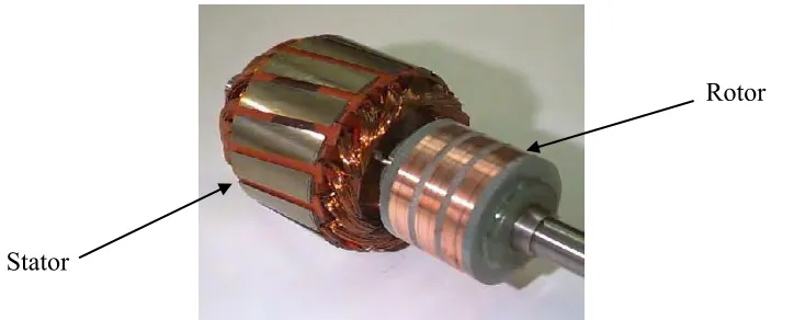
[image:14.612.167.529.510.656.2]AC motor is an electrical device that is powered by AC sourse. Many home appliances such as refrigerator, air-conditonioner, washing machine, vacuum cleaner, to name a few, are using AC motor to operate. Internally, an AC motor consists of two basic parts, stator and rotor, as shown in Figure 1.1. Stator and rotor itself consist of winding that is responsible to generatre electromagnetic force for the rotor part to rotate. In order for AC motor to rotate, AC source must be supplied to the stator winding to create electromagnetic field. It will induce current in rotor winding, thus creating magnetic field at rotor part, subsequently generate an eletromechanial force to rotate the rotor.
Figure 1.1: Internal structure of AC motor
Rotor
2
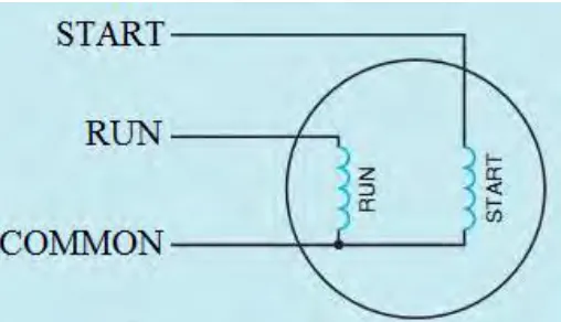
[image:15.612.197.451.192.338.2]AC motor can be powered by single phase or three phase AC soure, depending on their winding structure For single phase AC motor, the stator part consists of starting and running windings. The starting winding usually is to provide additional force during motor start-up. The existence of starting and running windings will create three terminal at motor input: start, run and common terminal as shown in Figure 1.2.
Figure 1.2: Run, start and common terminal of single phase AC motor
Since AC motor usually involve rotational movement and used in harsh and heavy duty applications, faulty and damage AC motor is common occurrences. However, repair technician always having problem in identifying terminals of single phase AC motor since motor manufacturer oftenly does not provide markings for the motor. In addition to that, there are also no standard color of wire that to recognize those terminals. These terminals can be identified by measuring the resistance between those terminals. The start and common terminal are manually identified based on the highest and the lowest reading of the terminal resistance. This process is time consuming and prone to decision error.
3
1.1 Problem Statement
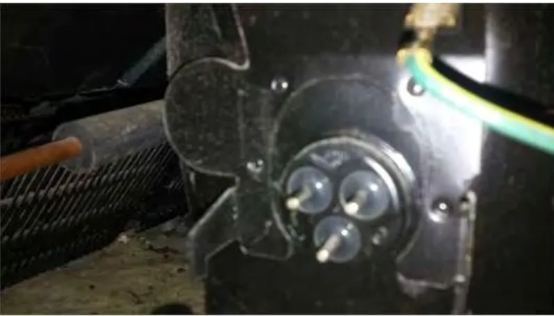
[image:16.612.150.548.291.518.2]Single phase AC motor consists of start, run and common terminals. Quite often, AC motor manufacturer does not provide marking or level of motor terminals. Furthermore, there is no standard of wire color motor terminals has been developed in industry. These problems have obscure the motor terminal identification especially by repair technician during troubleshooting process or motor replacement work. Figure 1.3 and Figure 1.4 show the terminal of AC motor for compressor of refrigerator and air-conditioner. Figure 1.5 and Figure 1.6 show the different color used for terminal AC motor.
4
Figure 1.4: Compressor for air-conditioner that does not have terminal markings (Brand: Nordyne, Model: FS3BA-018KA)
Figure 1.5: Single phase AC motor for exhaust fan Panasonic FV-20AUM8 (black wire - common terminal, white wire - start terminal, red wire - run
[image:17.612.179.514.379.619.2]5
Figure 1.6: Single phase AC motor for stand fan KDK KC40H (black wire – common terminal, red wire – start terminal, white wire – run terminal)
6
1.2 Objective
The aims of this project are:
a) To design a microcontroller based circuit for terminal identifier of single
phase AC motor.
b) To build hardware prototype which is easy to handled and can identify
the motor terminal instantly.
1.3 Work Scope
Scope of the project are as follows:
a) AC motor
The device will be designed to identify the terminals of single phase AC motor with single speed. This kind of motor widely used in air conditioner, ceiling fan, exhaust fan, to name a few.
b) Circuit design and simulation
The circuit of this project will be designed by using microcontroller – based ohmmeter and will be simulated by using proteus 8 professional.
c) Hardware prototype development
7
1.4 Thesis Outline
This thesis consists of five chapter and are organized as follows. Chapter 2 provides a literature review on information that is related in developing this project. The review of hardware components and several related previous works are also include in this chapter.
Chapter 3 provides the details methodology of process development. It covers the circuit design, hardware and programming development.
Chapter 4 discussed the results from simulation model circuit and hardware prototype. The analysis of results are also explained in this chapter
Finally, Chapter 5 presents the conclusion of this project. The recommendation
8
CHAPTER 2
LITERATURE REVIEW
2.0 Introduction
This chapter will discuss the study and analysis of previous project and will describe in detail about the components that is used for terminal identifier for single phase AC motor using microcontroller-based voltmeter as well as a description on the technology used. Before stating any project, some ideas from other researchers or other inventors are very useful. The ideas from their research likes mechanical design, control technique, program development and methodology serve a good input in developing this project. Thus, literature review is the beginning step to understand the ideas to develop this terminal identifier.
2.1 Microcontroller
Arduino is a software company, project, and user community that designs and manufactures computer open-source hardware, open-source software, and
microcontroller-based kits for building digital devices and interactive objects that can
9
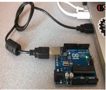
utilized to sense surroundings by using different transducers to examine and unravel inputs with a specific end goal to make reactions for instance through the controlling of engines or exchanging of information. As a bit of equipment, the Arduino can work either independently (like in a robot), connected directly with a PC (accordingly giving your PC access to sensor information from the outside world and giving input), or joined with different Arduino's, or other electronic gadgets and controller chips. Anything can be associated and is limited just by creative ability, readiness to put eventually and exertion into discovering some new information, and the accessibility of segments. Figure 2.1 shows how Arduino connected to the PC directly using USB cable:
[image:22.612.168.525.275.577.2]Figure 2.1: Arduino connected to PC
10
read the value. Current sensor also will give the value of current to Arduino Uno and then Arduino Uno will calculate based on formula ohms law’s and decide which terminal are start, common, running based on programming that will been build.
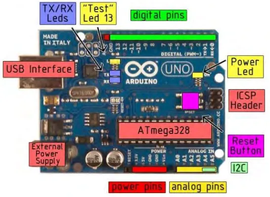
The Arduino Uno is a microcontroller board based on the ATmega328 . It has 14 digital input/output pins (of which 6 can be used as PWM outputs), 6 analog inputs, a 16 MHz crystal oscillator, a USB connection, a power jack, an ICSP header, and a reset button. It contains everything needed to support the microcontroller; simply connect it to a computer with a USB cable or power it with a AC-to-DC adapter or battery to get started.
[image:23.612.191.464.456.656.2]The Uno differs from all preceding boards in that it does not use the FTDI USB-to-serial driver chip. Instead, it features the Atmega8U2 programmed as a USB-USB-to-serial converter. "Uno" means one in Italian and is named to mark the upcoming release of Arduino 1.0. The Uno and version 1.0 will be the reference versions of Arduno, moving forward. The Uno is the latest in a series of USB Arduino boards, and the reference model for the Arduino platform. The Figure 2.2 is shown below
11
Microcontroller ATmega328
Operating Voltage 5V
Input Voltage (recommended) 7-12V
Input Voltage (limits) 6-20V
Digital I/O Pins 14 (of which 6 provide PWM output)
Analog Input Pins 6
DC Current per I/O Pin 40 mA
DC Current for 3.3V Pin 50 mA
Flash Memory 32 KB of which 0.5 KB used by bootloader
SRAM 2 KB
EEPROM 1 KB
Clock Speed 16 MHz
2.1.1 Power
The Arduino Uno can be powered via the USB connection or with an external power supply. The power source is selected automatically. External (non-USB) power can come either from an AC-to-DC adapter (wall-wart) or battery. The adapter can be connected by plugging a 2.1mm center-positive plug into the board's power jack. Leads from a battery can be inserted in the Gnd and Vin pin headers of the POWER connector.
The board can operate on an external supply of 6 to 20 volts. If supplied