UNIVERSITI TEKNIKAL MALAYSIA MELAKA
SOFT STARTER DESIGN FOR SINGLE PHASE
AC MOTOR USING MICROCONTROLLER – BASED
PHASE ANGLE CONTROL
This report is submitted in accordance with the requirement of the Universiti Teknikal Malaysia Melaka (UTeM) for the Bachelor of Electrical Engineering
Technology (Industrial Power) with Honours.
by
NGAN CHOON WANG B071410684 930923-04-5137
UNIVERSITI TEKNIKAL MALAYSIA MELAKA
BORANG PENGESAHAN STATUS LAPORAN PROJEK SARJANA MUDA
SULIT
TERHAD
TIDAK TERHAD
(Mengandungi maklumat yang berdarjah keselamatan atau kepentingan Malaysia sebagaimana yang termaktub dalam AKTA RAHSIA RASMI 1972)
(Mengandungi maklumat TERHAD yang telah ditentukan oleh organisasi/badan di mana penyelidikan dijalankan)
Alamat Tetap: 516 – 2 Batu 7 1/4
Bukit Rambai 75250 Melaka
Tarikh: ________________________
Disahkan oleh:
Cop Rasmi:
Tarikh: _______________________
** Jika Laporan PSM ini SULIT atau TERHAD, sila lampirkan surat daripada pihak berkuasa/organisasi berkenaan dengan menyatakan sekali sebab dan tempoh laporan PSM ini perlu dikelaskan sebagai SULIT atau TERHAD.
TAJUK: Soft Starter Design for Single Phase AC Motor using Microcontroller - Based Phase Angle Control
SESI PENGAJIAN: 2017/18 Semester 2
Saya NGAN CHOON WANG
mengaku membenarkan Laporan PSM ini disimpan di Perpustakaan Universiti Teknikal Malaysia Melaka (UTeM) dengan syarat-syarat kegunaan seperti berikut:
1. Laporan PSM adalah hak milik Universiti Teknikal Malaysia Melaka dan penulis. 2. Perpustakaan Universiti Teknikal Malaysia Melaka dibenarkan membuat salinan untuk
tujuan pengajian sahaja dengan izin penulis.
3. Perpustakaan dibenarkan membuat salinan laporan PSM ini sebagai bahan pertukaran antara institusi pengajian tinggi.
DELCARATION
I hereby, declared this report entitled “Soft Starter Design for Single Phase AC Motor using Microcontroller – Based Phase Angle Control” is the results of my
own research except as cited in references.
Signature :……….
Author’s Name : NGAN CHOON WANG
APPROVAL
This report is submitted to the Faculty of Engineering Technology of UTeM as a partial fulfilment of the requirement for the degree of Bachelor of Electrical Engineering Technology (Industrial Power) with Honours. The member of the supervisory is as follow:
……….
i
ABSTRAK
Apabila sebuah motor arus ulang alik (AU) dihidupkan menggunakan pemula berasaskan penyentuh/geganti, motor tersebut akan menghasilkan arus elektrik yang tinggi. Keadaan seperti ini tidak digemari di dalam sistem pengagihan kuasa kerana akan berlakunya kejatuhan kuasa untuk satu tempoh yang pendek dan juga boleh menyebabkan peranti perlindungan untuk memutuskan litar bekalan elektrik. Menghidupkan atau mematikan sesebuah motor AU secara mengejut akan menghasilkan gegaran yang menjurus kepada tekanan mekanikal terhadap struktur asas motor tersebut. Untuk mengatasi keadaan tersebut, sebuah peranti pemula lembut telah direka dan dibangunkan dengan menggunakan pengawal sudut fasa berasakan pengawal mikro.
Simulasi projek ini dibuat menggunakan perisian Proteus 7. Prototaip projek ini dihasilkan dengan menggunakan Arduino Uno sebagai pengawal dan disambungkan bersama paparan cecair kristal dan pengesan silang sifar sebagai isyarat masukkan. Litar berasaskan Triode for Alternating Current (TRIAC) akan digunakan untuk konduktiviti sudut fasa bekalan AU untuk memacu motor AU satu fasa.
ii
ABSTRACT
An AC motor draws high initial starting current that is many times greater than the rated current of the motor by using contactor/relay-based starter. This condition is not favourable in power distribution system since it can lead to power sags for a short period, and also may cause protection device to trip. Sudden start and stop of AC motor also can cause harsh vibration thus lead to mechanical stress of motor base structure. To overcome these problem, a soft starter device will be designed and developed based on microcontroller-based AC phase angle control.
The simulation work of this project is performed by using Proteus 7 software. The prototype is developed by using Arduino Uno as main controller interfaced with Liquid Crystal Display (LCD) display and zero-cross detector as input signal. Triode for alternating current (TRIAC) – based circuit to control AC conductivity phase angle is used to drive single phase AC motor.
iii
DEDICATION
iv
Acknowledgement
First and foremost, I, Ngan Choon Wang, B07140684 would like to thank Unversiti Teknikal Malaysia Melaka and Faculty of Engineering Technology for giving me the opportunity to conduct this project in my final year project. I start this project on February 2017 and I have gain lots of knowledge about the operation of soft start of an AC motor. Hopefully, this knowledge and understanding will be helpful in the future.
Furthermore, I would like to express my highest gratitude to my supervisor, Dr Mohd Badril bin Nor Shah for supporting and providing encouragement throughout the completion of this project.
v
TABLE OF CONTENT
Abstrak i
Abstract ii
Dedication iii
Acknowledgement iv
Table of Content v
List of Figure vii
List of Abbreviations, Symbols and Nomenclatures ix
CHAPTER 1: INTRODUCTION 1
1.0 Project Background 1
1.1 Problem Statement 2
1.2 Objective 2
1.3 Project Scope 2
CHAPTER 2: LITERATURE REVIEW 4
2.0 Introduction 4
2.1 Basic Construction of AC Motor 4
2.1.1 Squirrel Cage Rotor 5
2.1.2 Wound Rotor 5
2.2 Induction Motor 7
2.2.1 Split Phase Motor 7
2.2.2 Capacitor Start Motor 8
2.2.3 Capacitor Start Capacitor Run Motor 10
vi
2.3 AC Motor and Starting Issues 11
2.3.1 DOL Starter 12
2.3.2 Star – Delta Starter 14
2.3.3 Frequency Converter 15
2.3.4 Soft Starter 16
2.4 Previous Related Work 18
CHAPTER 3: METHODOLOGY 19
3.0 Introduction 19
3.1 Circuit Design 21 3.2 Simulation 22 3.2.1 Developing Soft Starting Algorithm 23
3.3 Prototype Development 25 3.4 Field Testing and Performance 27 CHAPTER 4: RESULT AND DISCUSSION 28 4.0 Introduction 28
4.1 Circuit Simulation 28 4.2 Experimental Result 30
4.2.1 Modulated Waveform Result 30 4.2.2 Voltage Response Result 33 4.2.3 Current Response Result 33 CHAPTER 5: CONCLUSION AND FUTURE WORK 36
5.0 Conclusion 36
5.1 Future Work 37
REFERENCE 38
vii
LIST OF FIGURE
2.1 Parts of AC motor 6
2.2 Squirrel Cage Rotor 6
2.3 Wound Rotor 6
2.4 Split Phase Motor Schematics Diagram 8
2.5 Phasor Diagram Between IA and IM 8
2.6 Capacitor Start Motor Schematic Diagram 9
2.7 Phasor Diagram of Capacitor Start Motor 9
2.8 Capacitor Start Capacitor Run Schematic Diagram 10
2.9 Shaded Pole Motor Schematic Diagram 11
2.10 DOL Wiring Diagram 13
2.11 Torque Speed Curve of DOL Starter 13
2.12 Current Curve of DOL Starter 14
2.13a Star Delta Main Configuration 15
2.13b Control Circuit 15
2.14 Torque and Current Characteristics 16
2.15 Regulated Input Voltage Sequence 17
2.16 TRIAC equivalent Diagram and Schematic Diagram 17
2.17 I – V Characteristics of TRIAC 17
3.1 Flowchart of Methodology for This Project 20
3.2 Field Diagram of This Project 21
3.3 The Schematics Diagram of Soft Starter using Microcontroller – Based Phase angle Control Circuit
22
3.4 The Programming Flowchart for This Project 23
3.5 Illustration associated to the developed soft starter algorithm 25
3.6 Arduino UNO 25
3.7 16 x 2 LCD display 26
viii
3.9 TRIAC circuit 27
3.10 Developed Soft Starter and Single Phase Induction Motor 27
4.1 20% of Modulated Waveform 29
4.2 50% of Modulated Waveform 29
4.3 75% of Modulated Waveform 29
4.4 100% of Modulated Waveform 29
4.5 20% of the Modulated Waveform with Resistive Load 30 4.6 50% of the Modulated Waveform with Resistive Load 31 4.7 100% of the Modulated Waveform with Resistive Load 31 4.8 20% of the Modulated Waveform with Inductive Load 31 4.9 50% of The Modulated Waveform with Inductive Load 32 4.10 100% of the Modulated Waveform With Inductive Load 32
4.11 Soft Starter and DOL Voltage Response 33
4.12 Current Response for Soft Starter with Time To Start is 10 Seconds
34
4.13 Current Response for Soft Starter with Time To Start is 20 Seconds
34
4.14 Current Response for Soft Starter with Time To Start is 30 Seconds
34
4.15 Current Response for Soft Starter with Time To Start is 40 Seconds
35
4.16 Current Response for Soft Starter with Time To Start is 50 Seconds
35
ix
LIST OF ABBREVIATIONS, SYMBOLS AND
NOMENCLATURES
AC - Alternating Current
LCD - Liquid Crystal Display
TRIAC - Triode for Alternating Current
IDE - Integrated Development Environment
SCR - Silicon Controlled Rectifier
DOL - Direct On – Line
R1 - Resistor 1
R2 - Resistor 2
NS - Synchronous Speed
CR - Permanent Capacitor
CS - Starting Capacitor
HP - Horsepower
I – V - Current against Voltage
WSCC - With Starting Current Control
WOSCC - Without Starting Current Control
LED - Light Emitting Diode
⌊… ⌋ - Floor
1
CHAPTER 1
INTRODUCTION
1.0 Project Background
Single phase AC motor is a machine that convert electrical energy in a form of alternating current into mechanical energy. Furthermore, AC motor is cheap, excellent operation and high efficiency in executing the daily tasks, therefore it is widely used in industrial and domestic applications such as air compressor, hoist and centrifugal pump.
Aside from the advantages, there are issues related to AC motor which are the inrush current is relatively high during initial starting condition and vibration due to the sudden development of high starting torque which eventually reduce the life span of the motor. Thus, the solution to this problems is to implement a soft starter device.
2
1.1
Problem StatementIt is well known that upon activation of high-power asynchronous and synchronous motors, large starting current is generated, which may leads to drops in the voltage of the supplying network (Williams et.al , 1978). This condition will reduce the life span of the motors. Besides that, the sudden inrush current will produce high torque that cause vibration and indirectly give mechanical stress toward the base structure of the motor thus increases maintenance costs on the motor.
1.2 Objective
The primary objective of this project is to develop a soft starter design for single phase AC motor using microcontroller – based phase angle control. At the end of this project, the objective that are going to be achieved are as follow:
(i) To design microcontroller based circuit of AC phase control to provide the operation of soft starter on single phase AC motor.
(ii) To develop soft starter algorithm based on designed circuit.
(iii) To build hardware prototype of this project to verify the efficiency of the designed circuit and soft start algorithm.
1.3 Project Scope
3 (i) Single Phase AC Motor
The prototype is developed by using microcontroller to provide soft starting to an AC motor by modulating the AC phase angle. Air conditioning and refrigerator compressor, water pump and centrifugal fan are some application that using single phase AC motor.
(ii) Microcontroller Programming
The platform that use to create the AC phase angle modulation algorithm is Arduino IDE software since the microcontroller that used to execute the algorithm is Arduino Uno.
(iii) Simulation
The developed algorithm simulation and the designed circuit will be virtually simulated using Proteus 7 software.
(iv) Hardware
4
CHAPTER 2
LITERATURE REVIEW
2.0 Introduction
Literature review is an important part before commencing any project. It provide all required information that related to the project and based on that, the correct direction in developing the project can be performed efficiently.
In this chapter, topics that will be explained are basic construction of AC motor, induction motor, starting methods and previous related works.
2.1 Basic Construction of AC Motor
5
catapult force will acts on the rotor, which produce a net torque to rotate the motor in the same direction as the rotating magnetic field.
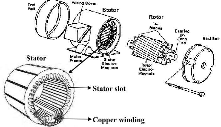
Figure 2.1 shows the parts of an AC motor. AC motor consists of two main parts, which are stator and rotor. Stator is a fix part of the ac motor that located inside of the motor frame and consists of bundles of laminated copper winding that filled on the stator slots. The purpose of stator are used to create magnetic field for the motor through the process of electromagnetism. While rotor is a hollow laminated core consists of slots on its external periphery that mounted on the shaft of the motor. These slots will be filled with rotor windings. There are two type of rotors which are squirrel cage rotor as shown in Figure 2.2 and wound rotor as shown in Figure 2.3, and are explained as the followings:
2.1.1 Squirrel Cage Rotor
Consists of laminated cylindrical iron core with parallel slot on it external periphery. The parallel slots are placed with either copper or aluminium bar and joined at each end by a pair of end rings. The construction of the rotor are similar with a squirrel cage, that how the name came from. This type of rotor basically used in induction motor because the current produced in the rotor are through induction process. The absent of slip ring in the construction of squirrel cage rotor, will cause high staring torque due to the addition of external resistance to the rotor are impossible.
2.1.2 Wound Rotor
6
[image:19.595.160.513.137.340.2]external resistance are made possible. Thus, the speed and starting torque of wound motor are possible to control.
[image:19.595.186.484.381.737.2]Figure 2.1: Parts of AC motor (Stephen, 2012)
Figure 2.2: Squirrel cage rotor
Figure 2.3: Wound rotor
[image:19.595.184.491.387.518.2]7 2.2 Induction Motor
Induction motor is a motor where torque is produced through the process of varying magnetic field in the stator and induced current in the rotor coil. Most of the induction motor are using squirrel cage rotor, thus it only depends on electromagnetic induction to induce voltage and current to rotate the motor. Furthermore, the characteristics of single phase induction motor that producing a pulsating magnetics field cause the motor to stay in stationary condition (Stephen, 2012). In order for the induction motor to create revolving magnetic field, auxiliary winding that controlled by a centrifugal switch is added to the main winding, after the motor attain it nominal speed, the auxiliary winding are removed. Generally, the induction motor is classified as split phase induction motor, capacitor start motor, capacitor start capacitor run motor, and shaded pole motor, and are explained as follows:
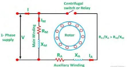
2.2.1 Split Phase Motor
8
[image:21.595.227.449.85.203.2]Figure 2.4: Split phase motor schematic diagram
Figure 2.5: Phasor diagram between IA and IM
Characteristic of split phase motor is as the following:
Starting torque are approximately 1.5 to 2 times the full load torque and the starting current is about 6 to 8 times the full load current.
Most popular single phase motor, because split phase motor are cheap.
The speed variation of this motor between 2 to 5% from no load to full load, thus they are basically a constant speed motor.
This motor are widely used in application where moderate starting torque is needed and motor start-up are less such as washing machine, small machine tools, oil burner, blower and domestic refrigerators.
Power rating of these motor are between 60 to 250 Watts (W).
2.2.2 Capacitor Start Motor
9
Im approximately by 80º. Subsequently, a greater net torque will be produced compared to split phase motor. During starting, both the winding are energised for the input, then the motor will start to rotate with less humming noise because of the capacitor. After the, motor reach about 75 to 80 percent of the synchronous speed the centrifugal switch, Sc will cut off auxiliary winding from the main winding and the motor will continue to rotate. The above statement are referring on Figure 2.6 and Figure 2.7
[image:22.595.192.469.179.514.2]Figure 2.6: Capacitor start motor schematic diagram
Figure 2.7: Phasor diagram of capacitor start motor
Characteristics of capacitor start motor are:
Due to the addition of capacitor, CS the current in auxiliary winding is reduced to half compare to the current in split phase motor for the same starting torque.
Therefore, auxiliary winding in capacitor start motor heat up slower compare to split phase motor
Have high starting torque, thus these motor are suitable in high inertia load and frequent starting application such as compressor, large fans and pumps.
10 2.2.3 Capacitor Start Capacitor Run Motor
Capacitor start capacitor run motor is a balanced 2 phase motor. They are designed with a main and auxiliary winding permanently connected together as shown in Figure 2.8. Since both of the windings are permanently connected, the revolving magnetic field that created by this motor are constant. The motor has 2 capacitor, the permanent capacitor (CR) and the starting capacitor (CS). Permanent capacitor is typically between 10 to 20 percent of the size of the starting capacitor. As a result, the power factor and efficiency of the motor are improved. For optimum starting CS will connected in parallel with CR and remains in the circuit during starting. As the rotor speed are approaching 80 percent of synchronous speed, centrifugal switch will disconnect CS from CR and the motor will continue to run as 2 phase induction motor.
Figure 2.8: Capacitor start capacitor run schematic diagram
Characteristics of capacitor start capacitor run motor are:
Ideal 2 phase motor that operated on any load.
The motor produce a constant torque due to the main and auxiliary winding are permanently connected.
11 2.2.4 Shaded Pole Motor
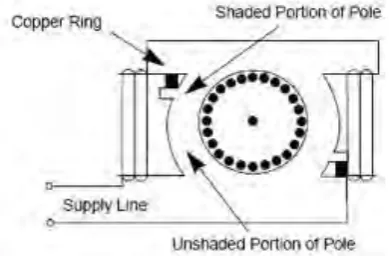
[image:24.595.220.415.321.449.2]Shaded pole motor is a self-starting single phase induction motor that designed with only a main winding in the stator. It has salient poles stator that divided into 2 part the shaded part and unshaded part and the shaded part of each pole is surrounded by a copper ring or short circuited coil named as shading coil. The stator is constructed in a special way to produce a moving magnetic field as the magnetic field varies. As the moving magnetic field sweep across the surface of the rotor a smell net torque is produced and the motor will start to rotate. The magnetic field will varies from the unshaded part to shaded part. Figure 2.9 indicate the schematics diagram of shaded pole motor
Figure 2.9: Shaded pole motor schematic diagram
Characteristics of shaded pole motor are provided as the following:
The motor is simple in construction, cheap, but poor efficiency
Has low starting torque, thus it is suitable to apply in low power application such as small fans, toys and desk fan.
2.3 AC Motor and Starting Issues